US1663255A - Electric pipe heater - Google Patents
Electric pipe heater Download PDFInfo
- Publication number
- US1663255A US1663255A US752141A US75214124A US1663255A US 1663255 A US1663255 A US 1663255A US 752141 A US752141 A US 752141A US 75214124 A US75214124 A US 75214124A US 1663255 A US1663255 A US 1663255A
- Authority
- US
- United States
- Prior art keywords
- pipe
- heater
- casing
- extension
- plate
- Prior art date
- Legal status (The legal status is an assumption and is not a legal conclusion. Google has not performed a legal analysis and makes no representation as to the accuracy of the status listed.)
- Expired - Lifetime
Links
Images
Classifications
-
- H—ELECTRICITY
- H05—ELECTRIC TECHNIQUES NOT OTHERWISE PROVIDED FOR
- H05B—ELECTRIC HEATING; ELECTRIC LIGHT SOURCES NOT OTHERWISE PROVIDED FOR; CIRCUIT ARRANGEMENTS FOR ELECTRIC LIGHT SOURCES, IN GENERAL
- H05B3/00—Ohmic-resistance heating
Definitions
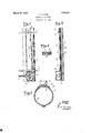
- Fig. 2 a transverse section
- Fig. 3 a longitudinal section of my device
- Fig. 4 is a cross section of the casing.
- My invention relates to an electric heater designed to be applied directly to a pipe which carries water or other tiuid which it is desired to heat without immersing the heater therein.
- A represents a pipe to which the heater is to be applied.
- the heater itself is a narrow, rigid and fiat body designed to lie longitudinally on the pipe and be secured thereto. It comprises a iiat, rigid casing B composed of a bottom plate or' metal b2 having its side edges bent up and across to overlie the side edges of a top plate I). Between the top and bottom plates is a body of refractory insulating material in which a resisting conductor is embedded. This casing is laid on the pipes longitudinally thereof, the bottom plate eing in contact with the pipe.
- top plate Above the top plate is a strip of heat insulation such as asbestos D, and over that is a wider strip E ot' metal having its side edges bent down to meet the curved surface of the pipe at a point below the level of the casing so as to limit lateral rocking of the. casing With respect to said pipe.
- a local metalbox or extension G At one end a local metalbox or extension G is seated above the plate E and secured by a rivet K which passes through the above said top .plate b and the plate E and also through an inturiied Harige on the lower edge of the extension.
- the opposite end of the extension is secuied by a strap passing under the bottom plate b2 and riveted to a similar inturned flange on the extension.
- the rivet K is one of two rivets K, K which secure the wide plate E and insulating plate D to the body of the heater.
- the extension G serves as a junction box for the electrical connections and on its floor are two connector terminals leading to the respective ends of the resistaing conductor aforesaid.
- the extension G also has a removable cover late and a side opening for the conduit C. hus the.
- extension is rigid with and ⁇ forms an essential part of the heater. This is oi material advantage, since it permits the heatei to be clamped to a pipe in a. wide variety of situations and under difficult conditions independently of the electric conductors which may be subsequently brought to the heater and connected thereto within the protected interior ot' the extension.
- the extension projects above the surface of the Hat heater and is therefore .accessible and of adequate size for making a good connection job.
- the heater is also provided with transverse flexible metal straps F, F, for clamping the heater to the pipe. These straps pass through loops on plate E and ai'e fastened together on the opposite sidel of the pipe by a bolt, as shown in ig. 2.
- the described device constitutes an article.
- An electric pipe-heater comprising a flat metal casing adapted to seat on the outside of the pipe, with a heating resistance enclosed therein, a hollow extension with a removable cover secured on the said casing and projecting above it, connectionterininals in the said extension, an insulating cover on the casing, a. metal plate on said cover, and means for clamping the casing on the outside of the pipe.
- An electric pipe-heater comprising a narrow rigid metallic casing adapted to rest longitudinally on the pipe and containing aV resisting conductor, an insulating plate outside said casing and a wider metallic cover extending down to meet the sides of the pipe below the level of the casing.
- An electric pipe heater comprising a fiat rigid metal casing adapted to seat on the exterior of the pipe to be heated, a heating resistance enclosed within said casing, a strip of heat insulating material above the top of said casing, and a metal support for said insulating material.
- Ari electric pipe heater comprising a. flat rigid metal casing adapted to seat on lll the exterior of a pipe to be heated, a ⁇ heating resistance enclosed Within said Casing, means secured to said easing for limiting lateral rocking thereof, and means for seeurino Said easing to the pipe.
- fin elect-rie pipe heater comprising a flat rigid metal casing adapted to seat on the exterior of e pipe to he heated, e hea-ting resistance enclosed Within ySeial easing, means secured to said easing for limiting lateral rocking thereof, e ⁇ hollow extension secured. te said easing and to said rocking limiting ineens, heater connection terminals in said extension, and ineens for securing szii'tl easing to the pipe.
- An electric pipe heater comprising a Het rigid metal easing adapted to seat on the exterior of the pipe to loe heated, e, heating resistance- Within seid easing, e plate above the top of said easing provid-ed with loops, and straps passed through said loops to secure the heater to a pipe.
Description
March 20, 1928.
L. P. HYNES ELECTRIC PIPE HEATER Filed Nov. 25. 1924 'I NvENoR LEE P. HYNES Patented Mar. 20, 1928.
UNITED STATES PATENT OFFICE.
LEE P. HYNES, 0F ALBANY, NEW YORK, ASSIGNOR T0y HYNES & COX ELECTRIC COR- PORATION, OF ALBANY, NEW YORK, A CORPORATION OF NEW YORK.
ELECTRIC PIPE HEATER.
Application filed November 25, 1924. Serial No. 752,141.
For a detailed description of the present form of my invention, reference may be had'to the following specification and to the accompanying drawing forming a part thereof, wherein Fig. l is a plan,
Fig. 2 a transverse section, and
Fig. 3 a longitudinal section of my device;
Fig. 4 is a cross section of the casing.
My invention relates to an electric heater designed to be applied directly to a pipe which carries water or other tiuid which it is desired to heat without immersing the heater therein.
Referring to t-he drawings, A represents a pipe to which the heater is to be applied. The heater itself is a narrow, rigid and fiat body designed to lie longitudinally on the pipe and be secured thereto. It comprises a iiat, rigid casing B composed of a bottom plate or' metal b2 having its side edges bent up and across to overlie the side edges of a top plate I). Between the top and bottom plates is a body of refractory insulating material in which a resisting conductor is embedded. This casing is laid on the pipes longitudinally thereof, the bottom plate eing in contact with the pipe. Above the top plate is a strip of heat insulation such as asbestos D, and over that is a wider strip E ot' metal having its side edges bent down to meet the curved surface of the pipe at a point below the level of the casing so as to limit lateral rocking of the. casing With respect to said pipe. At one end a local metalbox or extension G is seated above the plate E and secured by a rivet K which passes through the above said top .plate b and the plate E and also through an inturiied Harige on the lower edge of the extension. The opposite end of the extension is secuied by a strap passing under the bottom plate b2 and riveted to a similar inturned flange on the extension. The rivet K is one of two rivets K, K which secure the wide plate E and insulating plate D to the body of the heater. The extension G serves as a junction box for the electrical connections and on its floor are two connector terminals leading to the respective ends of the resistaing conductor aforesaid. The extension G also has a removable cover late and a side opening for the conduit C. hus the.
extension is rigid with and` forms an essential part of the heater. This is oi material advantage, since it permits the heatei to be clamped to a pipe in a. wide variety of situations and under difficult conditions independently of the electric conductors which may be subsequently brought to the heater and connected thereto within the protected interior ot' the extension. The extension projects above the surface of the Hat heater and is therefore .accessible and of adequate size for making a good connection job. The heater is also provided with transverse flexible metal straps F, F, for clamping the heater to the pipe. These straps pass through loops on plate E and ai'e fastened together on the opposite sidel of the pipe by a bolt, as shown in ig. 2. The described device constitutes an article. that is strong, rugged and compact which can readily be carried about and clamped to a pipe at any desired point thereon under the most diflicult conditions and when applied is immune to dampness, rough usage, electrical troubles and other unfavorable incidents of practical SelVlCe.
lVliat I claim as new and desire to secure by Letters Patent is:
l. An electric pipe-heater comprising a flat metal casing adapted to seat on the outside of the pipe, with a heating resistance enclosed therein, a hollow extension with a removable cover secured on the said casing and projecting above it, connectionterininals in the said extension, an insulating cover on the casing, a. metal plate on said cover, and means for clamping the casing on the outside of the pipe.
2. An electric pipe-heater comprisinga narrow rigid metallic casing adapted to rest longitudinally on the pipe and containing aV resisting conductor, an insulating plate outside said casing and a wider metallic cover extending down to meet the sides of the pipe below the level of the casing.
3. An electric pipe heater comprising a fiat rigid metal casing adapted to seat on the exterior of the pipe to be heated, a heating resistance enclosed within said casing, a strip of heat insulating material above the top of said casing, and a metal support for said insulating material.
4. Ari electric pipe heater comprising a. flat rigid metal casing adapted to seat on lll the exterior of a pipe to be heated, a` heating resistance enclosed Within said Casing, means secured to said easing for limiting lateral rocking thereof, and means for seeurino Said easing to the pipe.
5. fin elect-rie pipe heater comprising a flat rigid metal casing adapted to seat on the exterior of e pipe to he heated, e hea-ting resistance enclosed Within ySeial easing, means secured to said easing for limiting lateral rocking thereof, e` hollow extension secured. te said easing and to said rocking limiting ineens, heater connection terminals in said extension, and ineens for securing szii'tl easing to the pipe.
6. An electric pipe heater comprising a Het rigid metal easing adapted to seat on the exterior of the pipe to loe heated, e, heating resistance- Within seid easing, e plate above the top of said easing provid-ed with loops, and straps passed through said loops to secure the heater to a pipe.
Signed at Albany, county of Albany and State of New York, this 22nd day of November, 19211.
LEE P. HYNES.
Priority Applications (1)
| Application Number | Priority Date | Filing Date | Title |
|---|---|---|---|
| US752141A US1663255A (en) | 1924-11-25 | 1924-11-25 | Electric pipe heater |
Applications Claiming Priority (1)
| Application Number | Priority Date | Filing Date | Title |
|---|---|---|---|
| US752141A US1663255A (en) | 1924-11-25 | 1924-11-25 | Electric pipe heater |
Publications (1)
| Publication Number | Publication Date |
|---|---|
| US1663255A true US1663255A (en) | 1928-03-20 |
Family
ID=25025065
Family Applications (1)
| Application Number | Title | Priority Date | Filing Date |
|---|---|---|---|
| US752141A Expired - Lifetime US1663255A (en) | 1924-11-25 | 1924-11-25 | Electric pipe heater |
Country Status (1)
| Country | Link |
|---|---|
| US (1) | US1663255A (en) |
Cited By (7)
| Publication number | Priority date | Publication date | Assignee | Title |
|---|---|---|---|---|
| US2459816A (en) * | 1945-05-31 | 1949-01-25 | Handley Brown Heater Company | Water heater conversion unit |
| US2523876A (en) * | 1941-01-28 | 1950-09-26 | Ardo Ab Oy | Electric thawer for pipes |
| US2585237A (en) * | 1946-04-03 | 1952-02-12 | Babcock & Wilcox Co | Method of making banded pressure vessels |
| US2608636A (en) * | 1951-02-20 | 1952-08-26 | D Albora John | Electric heating pad support |
| US2629354A (en) * | 1949-05-25 | 1953-02-24 | Babcock & Wilcox Co | Apparatus for making banded pressure vessels |
| US2674227A (en) * | 1949-05-02 | 1954-04-06 | Midstate Mfg Company | Livestock waterer with heater |
| US3331946A (en) * | 1964-10-08 | 1967-07-18 | Thermon Mfg Co | Electric pipe heater |
-
1924
- 1924-11-25 US US752141A patent/US1663255A/en not_active Expired - Lifetime
Cited By (7)
| Publication number | Priority date | Publication date | Assignee | Title |
|---|---|---|---|---|
| US2523876A (en) * | 1941-01-28 | 1950-09-26 | Ardo Ab Oy | Electric thawer for pipes |
| US2459816A (en) * | 1945-05-31 | 1949-01-25 | Handley Brown Heater Company | Water heater conversion unit |
| US2585237A (en) * | 1946-04-03 | 1952-02-12 | Babcock & Wilcox Co | Method of making banded pressure vessels |
| US2674227A (en) * | 1949-05-02 | 1954-04-06 | Midstate Mfg Company | Livestock waterer with heater |
| US2629354A (en) * | 1949-05-25 | 1953-02-24 | Babcock & Wilcox Co | Apparatus for making banded pressure vessels |
| US2608636A (en) * | 1951-02-20 | 1952-08-26 | D Albora John | Electric heating pad support |
| US3331946A (en) * | 1964-10-08 | 1967-07-18 | Thermon Mfg Co | Electric pipe heater |
Similar Documents
| Publication | Publication Date | Title |
|---|---|---|
| US1992593A (en) | Portable electric heater | |
| US1663255A (en) | Electric pipe heater | |
| US1657479A (en) | Electric heating device | |
| US2550751A (en) | Electric heating | |
| US1436657A (en) | Electrical heating device | |
| US1659774A (en) | Electric heating device | |
| US1492146A (en) | Electrically-heated cream-dipping kettle | |
| US1750640A (en) | Electrical water heater | |
| US1437481A (en) | Immersion water heater | |
| US1727842A (en) | Electric chamber | |
| US2491266A (en) | Electric water heater | |
| US1909140A (en) | Connecter for electric appliances | |
| US1597427A (en) | Steam iron | |
| US1699898A (en) | Electric heater | |
| US1980654A (en) | Electric heater | |
| US1420840A (en) | Portable water heater | |
| US1395635A (en) | Electric iron | |
| US1321649A (en) | Electric heating | |
| US1782825A (en) | Electric heater | |
| US1429397A (en) | Hand warmer | |
| US1357019A (en) | Electrically-heated water service and system | |
| US1477982A (en) | Electrical heater | |
| US2677040A (en) | Oil heater for automotive engines | |
| US962768A (en) | Electric sad-iron. | |
| US1668250A (en) | Electric laundry iron |