US1663243A - Window screen - Google Patents
Window screen Download PDFInfo
- Publication number
- US1663243A US1663243A US123663A US12366326A US1663243A US 1663243 A US1663243 A US 1663243A US 123663 A US123663 A US 123663A US 12366326 A US12366326 A US 12366326A US 1663243 A US1663243 A US 1663243A
- Authority
- US
- United States
- Prior art keywords
- screen
- window
- window frame
- casing
- rails
- Prior art date
- Legal status (The legal status is an assumption and is not a legal conclusion. Google has not performed a legal analysis and makes no representation as to the accuracy of the status listed.)
- Expired - Lifetime
Links
Images
Classifications
-
- E—FIXED CONSTRUCTIONS
- E06—DOORS, WINDOWS, SHUTTERS, OR ROLLER BLINDS IN GENERAL; LADDERS
- E06B—FIXED OR MOVABLE CLOSURES FOR OPENINGS IN BUILDINGS, VEHICLES, FENCES OR LIKE ENCLOSURES IN GENERAL, e.g. DOORS, WINDOWS, BLINDS, GATES
- E06B9/00—Screening or protective devices for wall or similar openings, with or without operating or securing mechanisms; Closures of similar construction
- E06B9/52—Devices affording protection against insects, e.g. fly screens; Mesh windows for other purposes
- E06B9/54—Roller fly screens
Landscapes
- Engineering & Computer Science (AREA)
- Structural Engineering (AREA)
- Life Sciences & Earth Sciences (AREA)
- Insects & Arthropods (AREA)
- Pest Control & Pesticides (AREA)
- Architecture (AREA)
- Civil Engineering (AREA)
- Wing Frames And Configurations (AREA)
Description
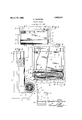
A. DAGROSA I WINDOW SCREEN Filed July 20 1926 INVENTOR Day r 05 Patented Mar. 20, 1928.
PATENT OFFICE.
AGUSTAL DAGROSA, OF NEW'YORK, N. Y.
WINDOW SCREEN.
Application filed July 20, 1926. Serial No. 123,663.
This invention relates to window screens and particularly to a device of this class and to be coupled with the lower rail of the lower sash whereby in the raising or open ing of the window, the body of screening material may be carried upwardly with the window to provide a screen closure for that W part of the window which is open; and the object of the invention is to provide a device of the class and for the purpose specified comprising a cylindrical casing with means rotatably mounted in the casing, upon which a body of screening material may be rolled, and a spring for actuating said means to give normal downward tension or pull on the screen material whereby in the operation of closing the window sash, the spring will operate to automatically wind the screen within said cylindrical casing; a further object being to provide means for quickly attaching and detaching said casing with relation to the window frame and also ifor attaching and detaching the free edge of the screen body with the lower rail of the lower sash, said casing attaching means including guide rails extending upwardly on the side rails of the window frame and in which the side edges of the screen are adapted to pass and be supported to provide a complete closure for the open portion of a window; and with these and other objects in view. the invention consists in a device of the class and for the purpose siplecified, which is simple in construction, e cient in use, and which is constructed as hereinafter described and claimed.
The invention is fully disclosed in the following specification, of which the accompanying drawing forms a part, in which the separate parts of my improvement are desig nated by suitable reference characters 1n each of the views, and in which Fig. 1 is an inside view of the lower portion of a window frame showing the lower sash in a partially raised position with my improved screen construction mounted in onnection therewith.
I on an enlarged scale.
Fig. 2 is a section on the line 2--2 of Fig.
Fig. 3 is a partial section on the line 3 -3 of Fig. 2 with parts of the construction broken away; and,
Fig. 4 is a detail view of the lower end portion of one of the guide rails and mounting brackets which liemploy.
In the drawing, I have indicated at 5, the framework of a window, 6 the sill portion of the window frame, and 7 the lower rail of the lower sash 8 of the window. In practice, I provide two guide rails 9 and 10 mounted in connection with the side rails of the window frame 5 on the inner side thereof and extending from the sill 6 to a point above the top of the lower sash when the same is in its lowermost and closed position.
The rails 9 and 10 are U-shaped in form in cross section to form channels 11 directed toward each other and in which the side edges of a screen body 12 are adapted to operate. The channels 11 of the rails 9 and 10 terminate short of the lower ends of said rail, said lower ends having inwardly directed bracket portions 13 having d'ovetailed grooves 14 closed at their outer ends by one wall 11 forming part of the channel 11 and the other ends are closed by pivot plates 15. I also provide a cylindrical or substantially cylindrical casing 16 having an opening 17 extending longitudinally of one side thereof, preferably the outer side with relation to the window frame. The u per edge of the casing at the opening 1 is curved upwardly and outwardly as seen at 18, Fig. 2 of the drawing, to" provide for the free passage of the body of screen material 12 thereover, while the other edge 19 is preferably turned inwardly to a slight degree to check the passage of rain water or the like into the casing, and especially such water as may drip from the screen body 12 when the same is in extended position. The ends of the casing 16 are closed by plates 20 and 21, said plates having at their outer faces, dove-tailed extensions 22 adapted to enter the dove-tailed recesses 14 of the brackets 13 as clearly seen in Fig. 3 of the drawing. The inner face of the end plate 20 is provided with an inwardly directed stud 23 on which a tubular shaft 24 is adapted to rotate, the adjacent end of the shaft 24 i rotatable on the bearing block 28 which is keyed to theboss by the engagement of the tongue 28 with the recess 27. A rather heavy spiral spring 30 is coupled with the block 29 as seen at 31, and the other end of said spring is coupled with another block or member32 secured to and constltutlng part of the shaft 24, it being understood that the block 32 maybe detachable with respect to said shaft. I
vThe above described construction of the casing 16, shaft. 24 and the several parts mounted in connection therewith is such that the spring 30, which will be normally wound up to the desired degree will operate to automatically wind the body of screen materlal '12 upon the shaft 24 when the Window sash 8 is lowered, it being understood that the end of the screen body 12 is secured to the shaft 24 to permit of the winding of the same thereon; on the other hand, when the sash 8 is raised, the tension on the spring .30 is increased, this result being accomlished by the rotation of the shaft 24 and Block 32, and retention of the block 29 against rotation in the end plate 21 or the boss 26 thereof. Y
The outer or free end of the screen body 12 is provided with an attaching plate or strip 33 secured thereto in any desired manner, which strip'is provided at spaced intervals with ke -hole apertures 34, the larger portions 0 which are directed downwardly as seen in Fig. 3 of the drawing. These apertures permit of the attachment of the strip 33 to headed pins, screws or the like 35 secured to the inner face of the lower rail 7 of the lower sash 8 at spaced intervals, corresponding with the spacing of the apertures 34. The strip 33 may be readily attached and detached by passing the heads of the pins 35 through the larger portions of said apertures as will be apparent. The ends of the strip 33 extend into the channels 11 and serve to guide the side edges of the screen body 12 upwardly and downwardly through side channels as will be apparent. The opening 11 provided at the lower ends of the channels 11 or between said channels and the bracket portions 13 will permit of the free passage of the ends of the attaching strip 33 outwardly through said chan-.
nels when it is desired to detach the screen casing 16 together with the screen body 12 I and strip 33 from the window frame in the operation of cleaning the windows or for any other purpose. In this connection, it
will be understood that the pivot strips 15 operate as catch devices for retaining the casing 16 againstaccidental displacement, and said strips are moved on their pivots to provide a free passage into and out of the dove-tailed recess 14 in the attachment and detachment of the casing 16.
One of the distinctive features of my invention is to provide a screen attachment for windows which is so simple in construction and operation as to permit of the quick attachment and detachment of the device whenever desired and to provide the greatest possible window opening, and also in the provision of an automatic screen of the class described which will not deface in any way, the window frame construction, or the sashes employed in the window frame nor necessitate the reconstructing or redesigning of a window frame of any conventional type or form, but consists merely in an attachment which may be readily applied to any type of window frame construction and which can be sold as an accessory in the manner of the sale of a roller shade, awning or like device.
- While I have shown certain details of construction for carrying my invention into effect, it will be understood that I am not necessarily limited to these details, and' various changes in and modifications of the structure herein shown'and described may be made within the scope of the appended claims without departing from the spirit of my invention or sacrificing its advantages.
Having fully described my invention what I claim as new lfiortions arranged angularly to said rails and aving dove-tailed sockets in which corre sponding members of the housing are adapted to be placed in detachably coupling the screen with the window frame.
2. In a spring roller window screen of the class described, a roller housing guide and mounting brackets for supporting the housing and screen in connection with the window frame and for guiding the same in its movement in said frame, said brackets being mounted at the opposite sides of the window and desire to secure by Letters Patent, is
frame and comprising rails of channel formation extending longitudinally of the side rails of the window frame and opening outwardly adjacent the lower ends of said means movably coupled with said bearing brackets, said brackets including bearing portions for retaining the screen against disportions arranged angularly to said rails placement therefrom. and having dove-tailed sockets in which In testimony that I claim the foregoing corresponding members of the housing are as my invention I have signed my name adapted to be placed in detachably coupling this 19th day of July, 1926. the screen with the window frame, and AGUSTAL DAGROSA.
Priority Applications (1)
| Application Number | Priority Date | Filing Date | Title |
|---|---|---|---|
| US123663A US1663243A (en) | 1926-07-20 | 1926-07-20 | Window screen |
Applications Claiming Priority (1)
| Application Number | Priority Date | Filing Date | Title |
|---|---|---|---|
| US123663A US1663243A (en) | 1926-07-20 | 1926-07-20 | Window screen |
Publications (1)
| Publication Number | Publication Date |
|---|---|
| US1663243A true US1663243A (en) | 1928-03-20 |
Family
ID=22410069
Family Applications (1)
| Application Number | Title | Priority Date | Filing Date |
|---|---|---|---|
| US123663A Expired - Lifetime US1663243A (en) | 1926-07-20 | 1926-07-20 | Window screen |
Country Status (1)
| Country | Link |
|---|---|
| US (1) | US1663243A (en) |
Cited By (1)
| Publication number | Priority date | Publication date | Assignee | Title |
|---|---|---|---|---|
| US3105542A (en) * | 1959-01-02 | 1963-10-01 | John N Zark | Roll up window screen |
-
1926
- 1926-07-20 US US123663A patent/US1663243A/en not_active Expired - Lifetime
Cited By (1)
| Publication number | Priority date | Publication date | Assignee | Title |
|---|---|---|---|---|
| US3105542A (en) * | 1959-01-02 | 1963-10-01 | John N Zark | Roll up window screen |
Similar Documents
| Publication | Publication Date | Title |
|---|---|---|
| US2281022A (en) | Shade construction | |
| US2141502A (en) | Venetian blind | |
| US1663243A (en) | Window screen | |
| US797652A (en) | Window-screen. | |
| US1395492A (en) | Window-screen | |
| US1793195A (en) | Roller screen for windows | |
| US1246570A (en) | Roll-screen for windows. | |
| US1538222A (en) | Screen | |
| US1707101A (en) | Revolving window or sash | |
| US1097140A (en) | Window-screen. | |
| US2562259A (en) | Venetian blind | |
| US2239006A (en) | Roller screen attachment for windows | |
| US1303081A (en) | Gilbert e | |
| US574959A (en) | Window-screen | |
| US1184208A (en) | Roller fly-screen. | |
| US767644A (en) | Roller-screen. | |
| US2175532A (en) | Venetian blind | |
| US716751A (en) | Window-screen. | |
| US1877596A (en) | Window screen | |
| US1388801A (en) | Window, door, or porch screen | |
| US1310305A (en) | smith | |
| US1917449A (en) | Roller shade | |
| US1303455A (en) | blackburn | |
| US305370A (en) | benedict | |
| US1278745A (en) | Window-screen. |