US1663242A - Stapling machine - Google Patents
Stapling machine Download PDFInfo
- Publication number
- US1663242A US1663242A US119843A US11984326A US1663242A US 1663242 A US1663242 A US 1663242A US 119843 A US119843 A US 119843A US 11984326 A US11984326 A US 11984326A US 1663242 A US1663242 A US 1663242A
- Authority
- US
- United States
- Prior art keywords
- stapling
- base
- machine
- auxiliary base
- bolt
- Prior art date
- Legal status (The legal status is an assumption and is not a legal conclusion. Google has not performed a legal analysis and makes no representation as to the accuracy of the status listed.)
- Expired - Lifetime
Links
Images

Classifications
-
- B—PERFORMING OPERATIONS; TRANSPORTING
- B25—HAND TOOLS; PORTABLE POWER-DRIVEN TOOLS; MANIPULATORS
- B25C—HAND-HELD NAILING OR STAPLING TOOLS; MANUALLY OPERATED PORTABLE STAPLING TOOLS
- B25C5/00—Manually operated portable stapling tools; Hand-held power-operated stapling tools; Staple feeding devices therefor
- B25C5/16—Staple-feeding devices, e.g. with feeding means, supports for staples or accessories concerning feeding devices
- B25C5/1679—Staple-feeding devices, e.g. with feeding means, supports for staples or accessories concerning feeding devices comprising storing arrangements for a plurality of staple strips
-
- B—PERFORMING OPERATIONS; TRANSPORTING
- B25—HAND TOOLS; PORTABLE POWER-DRIVEN TOOLS; MANIPULATORS
- B25C—HAND-HELD NAILING OR STAPLING TOOLS; MANUALLY OPERATED PORTABLE STAPLING TOOLS
- B25C5/00—Manually operated portable stapling tools; Hand-held power-operated stapling tools; Staple feeding devices therefor
- B25C5/10—Driving means
- B25C5/11—Driving means operated by manual or foot power
-
- B—PERFORMING OPERATIONS; TRANSPORTING
- B25—HAND TOOLS; PORTABLE POWER-DRIVEN TOOLS; MANIPULATORS
- B25C—HAND-HELD NAILING OR STAPLING TOOLS; MANUALLY OPERATED PORTABLE STAPLING TOOLS
- B25C5/00—Manually operated portable stapling tools; Hand-held power-operated stapling tools; Staple feeding devices therefor
- B25C5/16—Staple-feeding devices, e.g. with feeding means, supports for staples or accessories concerning feeding devices
- B25C5/1606—Feeding means
- B25C5/1624—Feeding means employing mechanical feeding means
- B25C5/1627—Feeding means employing mechanical feeding means of incremental type
Definitions
- My invention relates to new and useful improvements in stapling machines of the type employed for stapling together'two or more sheets of pap'er, and for stapling addressed tags or labels upon boxes, cartons and the like.
- One of the objects of the invention is to provide an improved auxiliary base and to provide improved means for detachably connecting the same to the stapling machine for the support of the machine thereon.
- Another object is to ⁇ provide improved' means for detachably connecting the stapling unit with the main base of the machine, so that the stapling unit may, at will, be used either with the base. of the machine for stapling together sheets of paper, or without the base of the machine for stapling tags or labels upon boxes, cartons and the like.
- Another object is to provide improved means by which positively to prevent a stapling strip from being fed forward a distance greater than one stapling unit at each reciprocation of the plunger.
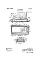
- Fig. 1 represents a side elevational view of a stapling machine embodying my present improvements
- Fig. 2 is a vertical section taken on the4 line 2 2 of Fig; 1;
- Fig. 3 is 'a fragmental vertical section
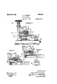
- Fig. 4 is a fragmental side elevational view of the machine showing the main base and the auxiliary base in section and withthe drawer broken away;
- Fig. 5 represents a horizontal section taken approximately on the line 5 5 of Fig. 4'
- Figais' a. vertical section' taken on the line 6-6 of Fig. 4;
- Fig. 7 represents a side elevational View of the machine with parts broken away to show the arrangement of the, stop element associated with the staple strip feeding means; l
- Fig. 8 represents another fragmental lside ine' means
- Fig. 9 is a view similar to that of Fig. 8, but showing a further modification of the stop arrangement for the staple strip feed- Fig. 10 represents in plan a fragment of the staple strip.
- I designates in general the stapling machine unit comprising a body 12, a plunger 13 arranged for verticall reciprocation at the front end of the body, a bolt 14 arranged for reciprocation in a horizontal bore 15 which extends inwardly into the body 0f the plunger, said bolt coacting with the plunger to be operated thereby and carrying a feed movement, and said bar 21 is connected forl up and down swinging movement with 'a main base 22 formed withdepending side langes 23 and a depending rear end flange 24 which connects the side flanges.
- the stapling machine unit 11 is detachably connected with the main base 22 so that it may, at will, be used either with the main base for stapling ktogether sheets of paper, or quickly removed from the main base for use in stapling tags or labels upon boxes, cartons and the like.
- the bar 21, at its rear end is swingably engaged between two ears 24- upstanding from the main base; and that the pivotal connection come prises a hinge pin 25 which passes throughsaid stud 27 being operatively held in position by means of a coiled spring 29 arranged within the bore 28 and imprisoned between the stud 27 and the screw plug 30 threaded into the outer-,end of the bore.
- the stapling machinel unit 11 is capable of being swung up and down upon thevhinge pin 25 where i-t ris used iny connection with the base 22; and when it 1s desired to use this stapling machine unit separately from the base, it is only necessary to pull out the pin 25 in order to sep'-y arate the unit from the base.
- I provide an auxiliary base, designated in general by the numeral 31, which is adapted to be detachably associated with the flanges of the main base and which is adapted to form a'bottom for the drawer chamber 32 produced by the depending flanges if the main base.
- I preferably provide notches as 37 in the upper plate and lugs 38 on the lower plate, which lugs after piercing the covering, ⁇ pass through said notches and are bent over uponl the upper plate as clearly shown in Fig. 5.
- angular clips 39 project upwardly from the edges defining the notches 37 atl the near rear end of theupper plate 34, said angular clips being adapted to be I entered yinto grooves 40 vprovi-ded in enlarged lugs 41 on the inner faces of the side flanges 23, and a cli' ⁇ 42 projects upwardly from the vfront en 'of the upper plate 34 for engagement in a ⁇ groove 43 in the rear flange 24.
- the upper plate 34 between the points where the lugs 38 are bentr over thereon is provided with shallow upstanding side flanges 44 "which engage on the inner faces of the side'ilanges 33 of the main base as best illustrated in Fig. 6, the ianges 35 of the plate 33 with the covering thereon engaging over vthe outer faces of said side flangesl 23 of the main base.
- a drawer 46 for holding a stock of staple strips occupies the drawer chamber 32 and is slidable upon the auxiliary base and between theside clips 39 and side lugs 38 thereon, as best shown 'in Fig. 5.
- a strip spring 47 is secured between the upper and lower plates 34 and 33 and extends upwardly through an aperture 48 vin the upperplate 34, so as to make pressure yupon the bottom of the drawer, the side flanges of the drawerl being preferably provided with cam-like top edges 49 for engagement with the underface of the main base as best'shown in Fig. 6.
- the bolt bore 15 is extended for a distance into'the body 12 and that apin 51 having a head 52 is loosely insertedy in the extended bore15, while the repositioning spring 50y is coiled about the pin 51 ,and imprisoned' between the pin head and the bolt ⁇ f14.
- the pin'51 vserx'fesasa stop for the bolt 14 and said pin is of the precise length necessary to arrest the movement of the bolt14 los at the pointwhere the feeding pawl ⁇ will engage the first'staple unitk 20.
- a modified form of the ⁇ stop arrangement is illustrated in Fifg. S'wherey it will be seen that a bore 53 ofreduced size extendsfrom the bolt bore 15 so as to provide a shoulder,
- an. auxiliary base structure composed of upper and lower plates; a covering for the lower plate clamped between the plates; lugs on the lower plate piercing said covering and bent over uponvthe upper plate; and V:attaching means on the upper plate, .substantially as ⁇ pocket, there being receiving grooves in said i anges, of an auxiliary base formin a bottom for said pocket; clip means on t e auxiliary base received in said grooves to fasten thev auxiliary base to said anges; a drawer in said pocket slidable upon said auxiliary base; and means on the auxiliary base engaging said drawer, substantially asv described.
Description
March 20;;1'92s. 1,663,242 l J. a. cRQr-'oo'r STAPLING MACHINE Filed July 1. 192e :s shuts-sheet 3 Patented Mar.v zo, 192s.
JOHN' B. CROFOO'I, OF ARLINGTON HEIGHTS, ILLINOIS. i
STAPLING MACHINE.
Application filed July 1,
My invention relates to new and useful improvements in stapling machines of the type employed for stapling together'two or more sheets of pap'er, and for stapling addressed tags or labels upon boxes, cartons and the like.
One of the objects of the invention is to provide an improved auxiliary base and to provide improved means for detachably connecting the same to the stapling machine for the support of the machine thereon.
Another object is to`provide improved' means for detachably connecting the stapling unit with the main base of the machine, so that the stapling unit may, at will, be used either with the base. of the machine for stapling together sheets of paper, or without the base of the machine for stapling tags or labels upon boxes, cartons and the like.
Another object is to provide improved means by which positively to prevent a stapling strip from being fed forward a distance greater than one stapling unit at each reciprocation of the plunger. 0
Other objects will appear hereinafterI The invention consists in the combinations and arrangements of parts hereinafter described Vand claimed.v f
The invention will be best understood by reference to the accompanying drawings forming a part of this specification, and in which, n
Fig. 1 represents a side elevational view of a stapling machine embodying my present improvements Fig. 2 is a vertical section taken on the4 line 2 2 of Fig; 1;
Fig. 3 is 'a fragmental vertical section |taken on the line 3 3 of Fig. 2;
Fig. 4 is a fragmental side elevational view of the machine showing the main base and the auxiliary base in section and withthe drawer broken away;
Fig. 5 represents a horizontal section taken approximately on the line 5 5 of Fig. 4'
Figais' a. vertical section' taken on the line 6-6 of Fig. 4;
Fig. 7 represents a side elevational View of the machine with parts broken away to show the arrangement of the, stop element associated with the staple strip feeding means; l
Fig. 8 represents another fragmental lside ine' means; and,
1926. Serial. N0. 119,843.
elevational view with parts broken away to show a modified form of the stop arrangenient for the staple strip feeding means;
Fig. 9 is a view similar to that of Fig. 8, but showing a further modification of the stop arrangement for the staple strip feed- Fig. 10 represents in plan a fragment of the staple strip.
In setting forth the preferred form of construction, I ,prefer to associate my improvements with a type of stapling machine heretofore invented by me, and in which 11 designates in general the stapling machine unit comprising a body 12, a plunger 13 arranged for verticall reciprocation at the front end of the body, a bolt 14 arranged for reciprocation in a horizontal bore 15 which extends inwardly into the body 0f the plunger, said bolt coacting with the plunger to be operated thereby and carrying a feed movement, and said bar 21 is connected forl up and down swinging movement with 'a main base 22 formed withdepending side langes 23 and a depending rear end flange 24 which connects the side flanges.
According to a feature of my improvements, the stapling machine unit 11 is detachably connected with the main base 22 so that it may, at will, be used either with the main base for stapling ktogether sheets of paper, or quickly removed from the main base for use in stapling tags or labels upon boxes, cartons and the like. In carrying out this provision, it will be seen that the bar 21, at its rear end, is swingably engaged between two ears 24- upstanding from the main base; and that the pivotal connection come prises a hinge pin 25 which passes throughsaid stud 27 being operatively held in position by means of a coiled spring 29 arranged within the bore 28 and imprisoned between the stud 27 and the screw plug 30 threaded into the outer-,end of the bore. By this arrangement, the stapling machinel unit 11 is capable of being swung up and down upon thevhinge pin 25 where i-t ris used iny connection with the base 22; and when it 1s desired to use this stapling machine unit separately from the base, it is only necessary to pull out the pin 25 in order to sep'-y arate the unit from the base.
According' to another feature of my 11nprovements, I provide an auxiliary base, designated in general by the numeral 31, which is adapted to be detachably associated with the flanges of the main base and which is adapted to form a'bottom for the drawer chamber 32 produced by the depending flanges if the main base. The auxiliary faces on which the machine may be placed,
the lfree edges of the covering being clamped i between the upper and lower plates 34 and 33. For securing the upper and lowerV plates together as a unit, I preferably provide notches as 37 in the upper plate and lugs 38 on the lower plate, which lugs after piercing the covering,` pass through said notches and are bent over uponl the upper plate as clearly shown in Fig. 5. For det-achably s ecuring the auxiliary base to ,the flanges, angular clips 39 project upwardly from the edges defining the notches 37 atl the near rear end of theupper plate 34, said angular clips being adapted to be I entered yinto grooves 40 vprovi-ded in enlarged lugs 41 on the inner faces of the side flanges 23, and a cli' `42 projects upwardly from the vfront en 'of the upper plate 34 for engagement in a `groove 43 in the rear flange 24. The
auxiliary base applied to the flanges by first inserting the clips39 in the grooves 40, an operation which is accomplished by moving the auxiliary base in a direction. from the front end of the main base, and then by pressing the auxiliary base against the iianges so that the hooklike clip 42 will snap into the groove 43. Preferably and as shown, the upper plate 34 between the points where the lugs 38 are bentr over thereon, is provided with shallow upstanding side flanges 44 "which engage on the inner faces of the side'ilanges 33 of the main base as best illustrated in Fig. 6, the ianges 35 of the plate 33 with the covering thereon engaging over vthe outer faces of said side flangesl 23 of the main base. To remove the auxiliary base, it is only necessary to insert a wire, nail or .other similar instrument through an opening 45 in the flange24 and press the hooklike clip 42 from its groove 43, Vwhereupon the clips 3 9 may be withdrawn from their grooves by drawing the auxiliary base in the forward direction.
A drawer 46 for holding a stock of staple strips occupies the drawer chamber 32 and is slidable upon the auxiliary base and between theside clips 39 and side lugs 38 thereon, as best shown 'in Fig. 5. means for holding the drawer 46 against acci-dental removal, a strip spring 47 is secured between the upper and lower plates 34 and 33 and extends upwardly through an aperture 48 vin the upperplate 34, so as to make pressure yupon the bottom of the drawer, the side flanges of the drawerl being preferably provided with cam-like top edges 49 for engagement with the underface of the main base as best'shown in Fig. 6.
Where the'plunger of the machinel is depressed by' means of ay mallet stroke or even where it'is depressed with great force by the As av hand,`it' sometimes happens that the ybolt 14 is thrustwith such force against its repositioning lspring 50y that the feeding pawl 16 is carried far enough'to effect the feeding of two staple unitsas 2() thereby clogging ythe operation of the machine. In order to prevent this excessive movement of the bolt 14, I preferably employ. the means shown in Fig.
'7 where it will be seen that ,the bolt bore 15 is extended for a distance into'the body 12 and that apin 51 having a head 52 is loosely insertedy in the extended bore15, while the repositioning spring 50y is coiled about the pin 51 ,and imprisoned' between the pin head and the bolt`f14. In this arrangement, the pin'51 vserx'fesasa stop for the bolt 14 and said pin is of the precise length necessary to arrest the movement of the bolt14 los at the pointwhere the feeding pawl `will engage the first'staple unitk 20. u y
A modified form of the` stop arrangement is illustrated in Fifg. S'wherey it will be seen that a bore 53 ofreduced size extendsfrom the bolt bore 15 so as to provide a shoulder,
54 at the precise position lwhere the bolt is to be arrested, the repositioning spring 55 in this instance extending 'as' shown' intothe reduced bore 53. A still further` modification is illustrated in Fig. 9 in ywhich I have shown a pin 56 secured with a drvejfitinthe reduced bore 57 which extends into the body 12, the forward extremityof this pinxbeing situated at the precise point lwhere it is necessary to arrest themovement of the bolt 14, and the yrepositioning spring 5:8, inthis ,instance beingfcoiled about E,the pin v56 and vimprisoned betweenthe end wall 59cofthe bore and the bolt. v
, WhileI have illustrated and describedthe preferred form of construction for carrying my invention into effect, this is capable of variationand modification without departing from the spirit of the invention. I, therefore, do not wish to be limited to the precise details of construction set forth, but desire to avail inyselz'fl of such variations and modifications as come within the scope of the appended claims.
Having described my invention, what l claim as new and desire to secure by Letters Patent is:
l. In a stapling machine, an. auxiliary base structure composed of upper and lower plates; a covering for the lower plate clamped between the plates; lugs on the lower plate piercing said covering and bent over uponvthe upper plate; and V:attaching means on the upper plate, .substantially as` pocket, there being receiving grooves in said i anges, of an auxiliary base formin a bottom for said pocket; clip means on t e auxiliary base received in said grooves to fasten thev auxiliary base to said anges; a drawer in said pocket slidable upon said auxiliary base; and means on the auxiliary base engaging said drawer, substantially asv described.
n testimony whereof I have name to this specification.
JoHN B. oaoroo'r.
signed `my
Priority Applications (1)
| Application Number | Priority Date | Filing Date | Title |
|---|---|---|---|
| US119843A US1663242A (en) | 1926-07-01 | 1926-07-01 | Stapling machine |
Applications Claiming Priority (1)
| Application Number | Priority Date | Filing Date | Title |
|---|---|---|---|
| US119843A US1663242A (en) | 1926-07-01 | 1926-07-01 | Stapling machine |
Publications (1)
| Publication Number | Publication Date |
|---|---|
| US1663242A true US1663242A (en) | 1928-03-20 |
Family
ID=22386714
Family Applications (1)
| Application Number | Title | Priority Date | Filing Date |
|---|---|---|---|
| US119843A Expired - Lifetime US1663242A (en) | 1926-07-01 | 1926-07-01 | Stapling machine |
Country Status (1)
| Country | Link |
|---|---|
| US (1) | US1663242A (en) |
Cited By (8)
| Publication number | Priority date | Publication date | Assignee | Title |
|---|---|---|---|---|
| US2445178A (en) * | 1943-09-11 | 1948-07-13 | Boston Wire Stitcher Co | Fastener-applying implement |
| US2580444A (en) * | 1945-12-12 | 1952-01-01 | Bocjl Corp | Fastener forming and driving device |
| US2606320A (en) * | 1950-11-28 | 1952-08-12 | John O Reece | Stapling tool |
| US2726393A (en) * | 1951-08-09 | 1955-12-13 | Neva Clog Products Inc | Storage compartment for staples on a stapling machine |
| US3302842A (en) * | 1965-03-04 | 1967-02-07 | Lendrum A Maceachron | Stapler |
| US4727610A (en) * | 1986-08-09 | 1988-03-01 | Lin Johnny C H | Multi-purpose stapler |
| US5797535A (en) * | 1997-05-14 | 1998-08-25 | Acco Usa, Inc. | Stapler with storage compartment and cover slipper |
| US20040216240A1 (en) * | 2001-12-11 | 2004-11-04 | Kramer Jeffrey A. | Stapler |
-
1926
- 1926-07-01 US US119843A patent/US1663242A/en not_active Expired - Lifetime
Cited By (8)
| Publication number | Priority date | Publication date | Assignee | Title |
|---|---|---|---|---|
| US2445178A (en) * | 1943-09-11 | 1948-07-13 | Boston Wire Stitcher Co | Fastener-applying implement |
| US2580444A (en) * | 1945-12-12 | 1952-01-01 | Bocjl Corp | Fastener forming and driving device |
| US2606320A (en) * | 1950-11-28 | 1952-08-12 | John O Reece | Stapling tool |
| US2726393A (en) * | 1951-08-09 | 1955-12-13 | Neva Clog Products Inc | Storage compartment for staples on a stapling machine |
| US3302842A (en) * | 1965-03-04 | 1967-02-07 | Lendrum A Maceachron | Stapler |
| US4727610A (en) * | 1986-08-09 | 1988-03-01 | Lin Johnny C H | Multi-purpose stapler |
| US5797535A (en) * | 1997-05-14 | 1998-08-25 | Acco Usa, Inc. | Stapler with storage compartment and cover slipper |
| US20040216240A1 (en) * | 2001-12-11 | 2004-11-04 | Kramer Jeffrey A. | Stapler |
Similar Documents
| Publication | Publication Date | Title |
|---|---|---|
| US1945377A (en) | Stapling machine | |
| US1663242A (en) | Stapling machine | |
| US2117741A (en) | Staple driving machine | |
| US2300277A (en) | Pin driving machine | |
| US2267185A (en) | Tie hook and forming die | |
| US1935280A (en) | Stapling machine | |
| US1290924A (en) | Attachment for shoe-stitching machines. | |
| US2239935A (en) | Stapling mechanism | |
| US1670898A (en) | Die | |
| US1840586A (en) | Piercing and stapling machine | |
| US2097051A (en) | Fastening device | |
| US2033599A (en) | Stapling device | |
| US195603A (en) | Improvement in devices for inserting metallic staples | |
| US430168A (en) | brown | |
| US1506073A (en) | Stapling machine | |
| US1637357A (en) | Paper-fastening device | |
| US1610632A (en) | Paper-fastening device | |
| US1222149A (en) | Stapling-machine. | |
| US2727234A (en) | Anvil structure for stapling machines | |
| US511154A (en) | Feed-gage for printing-presses | |
| US1481867A (en) | Stapling machine | |
| US1155141A (en) | Staple forming and setting implement. | |
| US1030781A (en) | Cutting and marking die. | |
| US1173119A (en) | Paper-fastening device. | |
| US1533986A (en) | Perforating attachment for printing presses |