US1663240A - Fastener - Google Patents
Fastener Download PDFInfo
- Publication number
- US1663240A US1663240A US719925A US71992524A US1663240A US 1663240 A US1663240 A US 1663240A US 719925 A US719925 A US 719925A US 71992524 A US71992524 A US 71992524A US 1663240 A US1663240 A US 1663240A
- Authority
- US
- United States
- Prior art keywords
- stud
- socket
- receiving part
- casing
- fastener
- Prior art date
- Legal status (The legal status is an assumption and is not a legal conclusion. Google has not performed a legal analysis and makes no representation as to the accuracy of the status listed.)
- Expired - Lifetime
Links
- 238000000926 separation method Methods 0.000 description 6
- 230000004075 alteration Effects 0.000 description 1
- 238000010276 construction Methods 0.000 description 1
- 239000000428 dust Substances 0.000 description 1
- 238000006467 substitution reaction Methods 0.000 description 1
Images
Classifications
-
- F—MECHANICAL ENGINEERING; LIGHTING; HEATING; WEAPONS; BLASTING
- F16—ENGINEERING ELEMENTS AND UNITS; GENERAL MEASURES FOR PRODUCING AND MAINTAINING EFFECTIVE FUNCTIONING OF MACHINES OR INSTALLATIONS; THERMAL INSULATION IN GENERAL
- F16B—DEVICES FOR FASTENING OR SECURING CONSTRUCTIONAL ELEMENTS OR MACHINE PARTS TOGETHER, e.g. NAILS, BOLTS, CIRCLIPS, CLAMPS, CLIPS OR WEDGES; JOINTS OR JOINTING
- F16B21/00—Means for preventing relative axial movement of a pin, spigot, shaft or the like and a member surrounding it; Stud-and-socket releasable fastenings
- F16B21/06—Releasable fastening devices with snap-action
-
- Y—GENERAL TAGGING OF NEW TECHNOLOGICAL DEVELOPMENTS; GENERAL TAGGING OF CROSS-SECTIONAL TECHNOLOGIES SPANNING OVER SEVERAL SECTIONS OF THE IPC; TECHNICAL SUBJECTS COVERED BY FORMER USPC CROSS-REFERENCE ART COLLECTIONS [XRACs] AND DIGESTS
- Y10—TECHNICAL SUBJECTS COVERED BY FORMER USPC
- Y10T—TECHNICAL SUBJECTS COVERED BY FORMER US CLASSIFICATION
- Y10T24/00—Buckles, buttons, clasps, etc.
- Y10T24/45—Separable-fastener or required component thereof [e.g., projection and cavity to complete interlock]
- Y10T24/45225—Separable-fastener or required component thereof [e.g., projection and cavity to complete interlock] including member having distinct formations and mating member selectively interlocking therewith
- Y10T24/45471—Projection having movable connection between components thereof or variable configuration
- Y10T24/45524—Projection having movable connection between components thereof or variable configuration including resiliently biased projection component or surface segment
- Y10T24/45539—Cooperating with cavity having side walls and axially biased component capping end
Definitions
- FIG. 2' is ⁇ a section on the line 2-2 of Fig. l', beingpartly in elevation,- and showing the *stud and socket lockedtogether; 19 'Figis a section similar toFig 2,and
- Y Fig. a is a section similar to Fig. 2, and
- Y Fig. 6 is afreareleva-tion of the stud
- Fig. 8 is a, front elevation ofthe socket
- a socket preferably -v taching yscrewa securedthereto in substantially the same manner as illustrated and described vin the (izo-pendingapplication' of Andrew G. Anderson, Serial'No. 708,724, filed' 'April 24th, 1924.
- the casing presents a iange 3 at Athe outer end thereof for engage'- ment' with the face of the support 4 to i which the socket'is attached, and the front 4 der- 5, the purposes lof whichare more fully hereinafter described.
- The' socket also includes a stud-receiving part 6 vpresenting af studreceiving aperture and a.
- the preferred form of stud for use with the Asocket herein described is secured to a frontl elevation ,of the 'pre "f'shows ,thestud moved axially 'intothe socket g1-nd* the lockingl member in unlocked posi-j' /f of the so-called flush type.
- the socket-,com- ⁇ prises a body part or casi'ngl 1 having an at-l ace of the 4casing'presents an annular shoul-y iexible carryingfabric'lO, and presents a vsocket-engaging contractible and expansible head lland a latch 12 pivot-ed thereupon.
- the neck is of the usual construction, having little orr no lost motion between .it and the stud-receiving part when the stud and socket are lockedftogether.
- Engagementoi Vthe stud and socket may lsocket thereby engaging the vhead oit'v the stud with the stud-receiving part adjacent ybe effected by pressingthe stud toward the the' stud-receiving aperture.
- the stud-receiving. part moves :axially inward against the pressure of theV spring ⁇ 8 yandfrelative to the socket until the end lof the tubular 'part seats against the head of the attaching screw.
- pressure urges the head to contract and enter the stud-receiving aperture at the same Vtime urging the locking member out of the aperture against the pressure of the spring 8.
- a socket including fa casing, a vstud-receiving part 4movable relative to said casing, a cooperating stud for engagement with said stud-receiving part, locking means forming part of the fastener assembly for locking said stud with the socket and unlocking means vseparate from lsaid locking means and carri'edby'said stud for displacing' said locking means to permit separation of the fastener when said stud and stud-receiving part are moved relative to s'aid casing.
- a stud and socket fastener comprising, in combination, a socket including a casing, a stud-receiving part movable relative to said casing, a cooperating stud for engagement with said stud-receiving part, locking means forming part of the fastener assembly fo'r locking said stud with the socket, a latch operable to displace said locking means and means adjacent said latchr to prevent tipping of said stud relative to said socket when lateral strain is exerted in the direction of said means.
- a stud and socket fastener comprising, in combination, a socket including a casing, a stud-receiving part movable relative to said casing, a vcooperating stud for engagement with said stud-receiving part, locking means forming part of the fastener assembly for locking'said stud with the socket, a latch operable to 'displace said locking means and a shoulder located upon said socket l ⁇ and engageable by said latch when a lateral strain is exerted upon 4said stud from above lsaid latch.
- a studand socket fastener comprising, in combination, a socket including a casing, 'a stud-receiving part axially movable in said casing and presenting a stnd-receivingaperture surrounded by a wall ofxed Vdimensions, and means forming part ofthe socket for limiting the movement of said ystud-receiving part, a stud having aj contractible and expansible head engageable W-ith said stud-receivingI part after movement thereof to its inner limited position and springpressed locking means within 'said stud-re'- DCving part for moving said stud and studreceiving part tok the forward limit and for locking said parts together.
- a stud and socket fastener comprising, in combination, a socket including a easing, a stud-receiving part axially mov-able in said casing and means for limiting the movement thereof, a stud-having a contractible and exp'ansible head e'ngageable with said stud-receiving part after movement thereof to its inner ,limited position, separate springpressed locking means forming part ofthe socket for -moving said stud and "stud-receiving part to the forward limit and locking said parts together, and an latch forming part of the fastener assembly 'and operable by inward-movement of said stud-receiving part relative to said casing to shift said loc-king means and permit separation of said stud and socketv Y 7.
- a stud and socket fastener compri-sing, in combination, a socket including aV shiftable stud-'receiving part, a stud for 'engagement therewith, resiliently pressed locking means carried by said socket for
- a socket for a separable fastener inclu-ding a casing, an axially movable springpressed stud-receiving part shiftable relative to said casing, said part presenting a stud-receiving aperture, means for limiting the shiftingl of said part in said casing, an axially shiftable spring-pressed closure plate forming part ⁇ of the socket assembly ⁇ and normally closing, said aperture to exclude dust and dirt from said socket, and locking means carried by said plate and presented at said aperture for engagement with and a spring normally urging said stud-rethe stud.
Landscapes
- Engineering & Computer Science (AREA)
- General Engineering & Computer Science (AREA)
- Mechanical Engineering (AREA)
- Snaps, Bayonet Connections, Set Pins, And Snap Rings (AREA)
Description
March 20, 1928.
F. S. CARR FASTENER Filed Jun 4.. e. f 44.413.. 1M/w... l.
c: c: A
Patented Mar. 20, 1928,.
l UNI-TED 'STATES raftitf Y` FWQE.
FRED s. CARR, oF, NEWTON, 'MassaCHUsnr'rs AssrGNoR 'ro CARB. FASTENER CCM- PANY, or CAMBRIDGE, MASSACHUSETTS, ,A Coarona'rron or'MaINn.
l FASTENER.
Y Appucatiun'fnee :rune` 14, 1924.. serial Nojviasas.
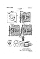
rIhis invention aims yto provide an improved" Jfastener of the push and'pull type. 'L ln the drawings,lwhich illustrate va Vpreterredr eichodimentl of myfinventionz ,FFifgur'el `is a Vferred fastener;- Y
Fig. 2'is`a section on the line 2-2 of Fig. l', beingpartly in elevation,- and showing the *stud and socket lockedtogether; 19 'Figis a section similar toFig 2,and
Y Fig. ais a section similar to Fig. 2, and
1 shows the stud being separated from the socketbyrelative tipping-action after the f rparts have assumed theposition'in Fig. 3; "Fig'..fisa-front elevation of the' stud;
Y Fig. 6 is afreareleva-tion of the stud;
'20 l -Figif is a section on the line 7-7-7 of Fig.
1 ,sho'wing the means of attaching vthe stud toacurt-ain; v Y
' Fig. 8 is a, front elevation ofthe socket;
l Fig. 9 is a side elevation of the socket. f
Referring to the drawings and to the preferred form 'of my invention as illustrated j therein, I have shown a socket preferably -v taching yscrewa securedthereto in substantially the same manner as illustrated and described vin the (izo-pendingapplication' of Andrew G. Anderson, Serial'No. 708,724, filed' 'April 24th, 1924. The casing presents a iange 3 at Athe outer end thereof for engage'- ment' with the face of the support 4 to i which the socket'is attached, and the front 4 der- 5, the purposes lof whichare more fully hereinafter described. 'The' socket also includes a stud-receiving part 6 vpresenting af studreceiving aperture and a. locking member 7 normally urged into aperture-closing positionby a spring 8 which lalso urges the stud-receiving part forward until. it seats against the front-facerof the casing."The stud-receiving part is preferably provided with a substantially long tubular part close.- ly slidably fitting the inside of the casing.
The preferred form of stud for use with the Asocket herein described is secured to a frontl elevation ,of the 'pre "f'shows ,thestud moved axially 'intothe socket g1-nd* the lockingl member in unlocked posi-j' /f of the so-called flush type. v The socket-,com-` prises a body part or casi'ngl 1 having an at-l ace of the 4casing'presents an annular shoul-y iexible carryingfabric'lO, and presents a vsocket-engaging contractible and expansible head lland a latch 12 pivot-ed thereupon.
` Theattaching means, the stud and the oprasant eration thereof are substantially illustrated and 'Umore fully described in my co-pending application filed herewith, Serial No. 719,-
924. The only substantial variation between the stud herein illustrated and, the stud illustrated in the above-mentioned application is 'in the neck: In this instance, the neck is of the usual construction, having little orr no lost motion between .it and the stud-receiving part when the stud and socket are lockedftogether.
Engagementoi Vthe stud and socket may lsocket thereby engaging the vhead oit'v the stud with the stud-receiving part adjacent ybe effected by pressingthe stud toward the the' stud-receiving aperture. As further vpressure is-applied'to enter the head in the aperture, the stud-receiving. part moves :axially inward against the pressure of theV spring`8 yandfrelative to the socket until the end lof the tubular 'part seats against the head of the attaching screw. Still further ,pressure urges the head to contract and enter the stud-receiving aperture at the same Vtime urging the locking member out of the aperture against the pressure of the spring 8. A'lfhus the-head enters the aperture and again expands, the neck thereof engaging the peripheralwall surrounding the studreceiving aperture. Pressure is now released from the stud and the spring 8 thenurges the. stud-receiving part (Sinto its normal `positionagain and at the same t-ime'gthe locking member -7 is free to be urged bythe v spring8 .into 'engagement with the reve-rselv bentportions of the stud, asbest illustiated in Fig. 2, therebylocking the stud.
and socket again-st separation by a pull at any side'thereof. The Studis also locked againstseparation by an upward pull becausethe end of theV latch that engages the face of the socket contacts with ,the annular shoulderf, which provides a very effective stop `thereby preventing a resolution of.
forces `from tipping the stud out of engagement with the stud-receiving part. l
Separation of the stud from the socket is eliected by first pressing the studv toward the best shown in Fig. 4.
`While I have shown and described a preferred form of one lembodiment of my 1nvention, it will be understood that changes involving omission, substitution, alteration and reversal of parts, and even changes in the mode of-operation, may be made'with- Aout departing from the scope of my invention, which is best dened in t-he following claims.
I claim- 1. A stud and 'socket fastener comprising,
in combination, a socket including fa casing, a vstud-receiving part 4movable relative to said casing, a cooperating stud for engagement with said stud-receiving part, locking means forming part of the fastener assembly for locking said stud with the socket and unlocking means vseparate from lsaid locking means and carri'edby'said stud for displacing' said locking means to permit separation of the fastener when said stud and stud-receiving part are moved relative to s'aid casing. Y Y
2. A stud and socket fastener lcomprising, in combination, a socket including a casing, a stud-receiving part movable relative to said casing, a cooperating stud for engagement with said stud-receiving part, locking means forming part of the fastener assembly fo'r locking said stud with the socket, a latch operable to displace said locking means and means adjacent said latchr to prevent tipping of said stud relative to said socket when lateral strain is exerted in the direction of said means.
3. A stud and socket fastener comprising, in combination, a socket including a casing, a stud-receiving part movable relative to said casing, a vcooperating stud for engagement with said stud-receiving part, locking means forming part of the fastener assembly for locking'said stud with the socket, a latch operable to 'displace said locking means and a shoulder located upon said socket l`and engageable by said latch when a lateral strain is exerted upon 4said stud from above lsaid latch.
4. A stud and socket fastener comprising, in combination, a socket including a casing, a stud-receiving part and a spring-pressed locking member normally urging said studreceivin'g part `into its forward position, a cooperating stud having a head for engagement with said stud-receiving part and adapted whenengaged therewith to receive said locking member to prevent separation of said stud from said stud-receiving part and a latch pivoted upon said head and operable by axial movement ofsaid stud and stud=receiving part relative to said 'casingv thereby to displace said locking member from said head and permit separation of said fastener.
5. A studand socket fastener comprising, in combination, a socket including a casing, 'a stud-receiving part axially movable in said casing and presenting a stnd-receivingaperture surrounded by a wall ofxed Vdimensions, and means forming part ofthe socket for limiting the movement of said ystud-receiving part, a stud having aj contractible and expansible head engageable W-ith said stud-receivingI part after movement thereof to its inner limited position and springpressed locking means within 'said stud-re'- ceiving part for moving said stud and studreceiving part tok the forward limit and for locking said parts together. Y Y
6. A stud and socket fastener comprising, in combination, a socket including a easing, a stud-receiving part axially mov-able in said casing and means for limiting the movement thereof, a stud-having a contractible and exp'ansible head e'ngageable with said stud-receiving part after movement thereof to its inner ,limited position, separate springpressed locking means forming part ofthe socket for -moving said stud and "stud-receiving part to the forward limit and locking said parts together, and an latch forming part of the fastener assembly 'and operable by inward-movement of said stud-receiving part relative to said casing to shift said loc-king means and permit separation of said stud and socketv Y 7.V A stud and socket fastener compri-sing, in combination, a socket including aV shiftable stud-'receiving part, a stud for 'engagement therewith, resiliently pressed locking means carried by said socket for'locking said stud with said stud-receiving part andV unlocking means pivotally mounted upon the `stud and operable relative to sai'd studr'eceiving part, without movement between the stud and stud-receiving part, to move said locking means into unlocking position relative to said stud.-
8. .A socket for a separable fastener inclu-ding a casing, an axially movable springpressed stud-receiving part shiftable relative to said casing, said part presenting a stud-receiving aperture, means for limiting the shiftingl of said part in said casing, an axially shiftable spring-pressed closure plate forming part `of the socket assembly `and normally closing, said aperture to exclude dust and dirt from said socket, and locking means carried by said plate and presented at said aperture for engagement with and a spring normally urging said stud-rethe stud. ceiving part and said locking member into 9, A socket for a separable fastener innormal position said stud-receiving part and 10 Vcluding a casing, means for attaching said said spring being assembled with said casing. 5 casing to a support, an axially movable non- In testimony whereof, I have signed my resilient stud-receiving part, a locking memname to this specification.
ber reciprocable in said stud-receiving part FRED S. CARR.
Priority Applications (1)
| Application Number | Priority Date | Filing Date | Title |
|---|---|---|---|
| US719925A US1663240A (en) | 1924-06-14 | 1924-06-14 | Fastener |
Applications Claiming Priority (1)
| Application Number | Priority Date | Filing Date | Title |
|---|---|---|---|
| US719925A US1663240A (en) | 1924-06-14 | 1924-06-14 | Fastener |
Publications (1)
| Publication Number | Publication Date |
|---|---|
| US1663240A true US1663240A (en) | 1928-03-20 |
Family
ID=24891935
Family Applications (1)
| Application Number | Title | Priority Date | Filing Date |
|---|---|---|---|
| US719925A Expired - Lifetime US1663240A (en) | 1924-06-14 | 1924-06-14 | Fastener |
Country Status (1)
| Country | Link |
|---|---|
| US (1) | US1663240A (en) |
-
1924
- 1924-06-14 US US719925A patent/US1663240A/en not_active Expired - Lifetime
Similar Documents
| Publication | Publication Date | Title |
|---|---|---|
| US3052940A (en) | Locking pin | |
| US1271650A (en) | Fastener. | |
| US2526790A (en) | Fastening device | |
| US2777718A (en) | Quick acting connector | |
| US2328016A (en) | One-way detachable snap fastener | |
| US3205759A (en) | Two-piece molding fastener | |
| US3125790A (en) | Releasable coupling | |
| US2819506A (en) | Fastening device | |
| US1663240A (en) | Fastener | |
| US1647781A (en) | Fastener | |
| US2567069A (en) | Detachable connector | |
| US3510922A (en) | Fastener stud assembly | |
| US3396436A (en) | Snap fastener assembly | |
| US1321974A (en) | of amesbury | |
| US2771653A (en) | Snap fastener socket | |
| US1664351A (en) | Fastener | |
| US1563351A (en) | Separable cuff button | |
| US1647773A (en) | Fastener | |
| US1247411A (en) | Vehicle-curtain fastener. | |
| US878550A (en) | Fastener. | |
| US2139145A (en) | Fastening device | |
| US1320832A (en) | Setts | |
| US1647778A (en) | Fastener | |
| US1647774A (en) | Fastener | |
| US1647782A (en) | Separable fastener |