US1663236A - Planter attachment for tractors - Google Patents
Planter attachment for tractors Download PDFInfo
- Publication number
- US1663236A US1663236A US125855A US12585526A US1663236A US 1663236 A US1663236 A US 1663236A US 125855 A US125855 A US 125855A US 12585526 A US12585526 A US 12585526A US 1663236 A US1663236 A US 1663236A
- Authority
- US
- United States
- Prior art keywords
- frame
- tractor
- planter
- steering
- units
- Prior art date
- Legal status (The legal status is an assumption and is not a legal conclusion. Google has not performed a legal analysis and makes no representation as to the accuracy of the status listed.)
- Expired - Lifetime
Links
- 238000010276 construction Methods 0.000 description 5
- 241000196324 Embryophyta Species 0.000 description 2
- RYGMFSIKBFXOCR-UHFFFAOYSA-N Copper Chemical compound [Cu] RYGMFSIKBFXOCR-UHFFFAOYSA-N 0.000 description 1
- 241000735495 Erica <angiosperm> Species 0.000 description 1
- 230000008878 coupling Effects 0.000 description 1
- 238000010168 coupling process Methods 0.000 description 1
- 238000005859 coupling reaction Methods 0.000 description 1
- 230000004048 modification Effects 0.000 description 1
- 238000012986 modification Methods 0.000 description 1
- 230000008520 organization Effects 0.000 description 1
Images

Classifications
-
- A—HUMAN NECESSITIES
- A01—AGRICULTURE; FORESTRY; ANIMAL HUSBANDRY; HUNTING; TRAPPING; FISHING
- A01C—PLANTING; SOWING; FERTILISING
- A01C7/00—Sowing
- A01C7/08—Broadcast seeders; Seeders depositing seeds in rows
Definitions
- This invention relates to farm implements and is directed more particularly to implements of the class adapted for attachment to and operation in conjunction with tractors.
- a further-object is to provide a structure that will be easily attachable to existing types of tractors and that will provide the desired arrangement of lanter units and also will include means or governing the operation of the planting elements when the structure is in position on a tractor.
- the projecting ends carrying planter units in such manner as lto provide for lifting and lowering movement thereof, and the connecting means between the planter units, transverse frame bar and tractor body including actuating means for the lifting and lowering mechanism which governs the operation of the planter units and which is controllable from a station on the tractor body.
- Figure 1 is a side elevation of the invention as applied to a common type of tractor
- the forward end of the body 10 issupported on a single centrally positioned steering truck l2. ⁇ These 'parts are shown in dotted lines on the drawings.
- the steering truck includes an upright steering postl journaled in a front cross member on the tractor frame, and the truck is steered through gearing 14 which transmits movement of the steering wheel and rod 15 to a' gear sector 16 on the upper end of the standard of the steering truck.
- brackets 17 On the forward corners of the tractor frame at each side of the steering post suit-k able supporting brackets 17 arek provided. These bracketsY cooperate with coupling elements carrying pivotally mounted forwardly extending supporting arms 18. These arms extend horizontally and at their forward ends are pivoted in clamp brackets 19 supporting a transversely extending frame member 20 which' projects laterally beyond 211 which may be vswung into allgnment with bar 2l and carries a pin on its under side adapted to engage in an opening 25 in bar 21, thereby locking the arms 18 and member 20 against lateral movement when desired.
- a forwardly projecting arm 26 which is connected to the vertical standard of the steer- ⁇ ing truck and shares its movement.
- the outer end of this arm is connected as by a' link 27 to an arm 28 on one of the clamp brackets 19.
- steering movement of the truck will be communicated to the member 20 to shift it in the direction of steering movement, which movement is limited by the llength of the slot 23 in arm 21.
- the supporting and shifting The extent of such lateral movemechanism for the frame bar 20, above dey scribed, may be of substantially the construe l29 on each of its projecting ends, which pairsA of members are arranged to straddle adjacent plant rows, which inl thisinstance are also straddled by the rear traction wheels of the tractor on which the planter attachment is mounted.
- Each pair of depending arms known type.
- Each planter unit is also pro-l 29 carries an arched crank member 30 which has horizontally extending angular portions pivoted in the .lower ends of the arms 29 'and an upwardly extending forwardly inclined arched portion, the upper portion 30 of which may swing in the space between the arms.
- the angular portions of the arch members 30 include transversely extending portions forming bearings for dragbars 31, the rear ends of which are fixed tofframes 32 carrying planter units. ⁇
- These units are shown in this instance as comprising the usual seed hopper and dispensing mechalnism 33 mounted at the center of the frame 32, which frame is supported at its rear on adjustable covering wheels 34 journaled in brackets 35, which are pivotally connected to the frame 32 and adjustable in the usual ⁇ manner by means of the lever 36.
- the forward end of the frame 32 at its point of connection with the dragbars 31 is supported on a wheel 37, and this wheel may be connected to the dispensing mechanism by a double crank and pitman construction 38 of well vided with the necessary furrow openers herein shown as twin disks 39.
- a lift operating rod 40 As means for lifting and lowering each planting unit and thereby governing its operation, there is provided a lift operating rod 40, the forward end of which is pivotally connected to the-arched portion 30a of the arched members 30. 4The rear end of this rod 40 is connected to a lever 41 which is4 pivoted on 'a bracket 42 provided with a locking rack for lever 41l and having means for connecting it to the rear axle structure of a tractor.
- traction and steering means supporting oposite ends ofthe frame, a carryingy memer extending across the front end of the body frame and projecting beyond it at each side, planter units positioned to trail at each side of the body frame and each having ground wheels normally supporting the unit,
- draft connections including means carried by the projecting ends of the carrying member lfor bodily lifting and lowering the planter units while maintaining said units in. parallel relation to the ground surface, and means operable from a station on the vehicle for actuating the lifting and lowering means.
- the combination comprising a selfpropelled vehicle having a longitudinal body frame, traction and steering means supporting the opposite ends of the frame, planter units positioned to trail vat each side of the body frame and each having ground wheels normally supporting the' unit, draft connections carried by the forward vportion of the body frame and connected thereto by laterallyshiftable means including means for bodilylifting and loweringthe planter units, and actuating means for the lifting and lowering means and for thel laterally shiftable carryingmeans operable from a station on the vehicle.
- planter units located on 'each side of the body frame in advance of the axle7 said units having horizontal frames having supporting Wheels at the front and rear7 means connecting each planter unit to the body frame' including vertically shiftable draft members connected to each unit at longitudinally spaced points on the frame, and means operable from theoperators station for shifting said supports to bodily raise and lower the planter units While maintaining the frames in parallel relation to the ground surface.
- a self-propelled vehicle comprising a rear axle housing having an operators station thereon and supported at its ends on traction Wheels and a body frame extending centrally from said housing and supported on a steering'truck, planter units located on each side of the body frame and truck and in advance of the ⁇ axle Within the treads of the traction wheels,
Landscapes
- Life Sciences & Earth Sciences (AREA)
- Soil Sciences (AREA)
- Environmental Sciences (AREA)
- Agricultural Machines (AREA)
Description
March 2.0, 1928.
B. R. BENJAMIN PLANTERATTACHMENT FOR TRAcToRs Filed July 5o, 192e 2 Sheets- Sheet 1 6N @Il @um uw QN ,uw
March 20, 1928.
B. R. BENJAMIN PLANTER ATTACHMENT FOR TRACTORS Filed July 30. 1926 Patented Mar. 20, 1928. y
UNrrEn sTArEs y latam' PATENT erica.
BERT B. BENJAMIN, 0F OAK PARK, 4ILLINOIS, ASSIGNOR T0 INTERNATIONAL HAB- VESTER COMPANY, A CORPORATION OF NEW JERSEY.
TLANTER ATTACHMENT FOR TRACTORS.
Application filed July 30,
This invention relates to farm implements and is directed more particularly to implements of the class adapted for attachment to and operation in conjunction with tractors.
The principal .object of the 1nvent1on 1s to provide means for converting farm tractors into efficient tractor planters when desired and to produce a tractor planter structure in`which the planter units will be positioned at each side of the forward. portion of the tractor body where they will be conveniently positioned for observation and control by the operator of the tractor.
.A further-object is to provide a structure that will be easily attachable to existing types of tractors and that will provide the desired arrangement of lanter units and also will include means or governing the operation of the planting elements when the structure is in position on a tractor. I
The foregoing and other minor objects have been attained by the provision of a structure having for its characteristic features of construction a transverse frame member attachable at its center to the front end of a tractor frame in a manner to provide for laterial adjustment or movement,
if desired, and having its ends projecting laterally well beyond the sides of the tractor body, the projecting ends carrying planter units in such manner as lto provide for lifting and lowering movement thereof, and the connecting means between the planter units, transverse frame bar and tractor body including actuating means for the lifting and lowering mechanism which governs the operation of the planter units and which is controllable from a station on the tractor body.
The invention accordingly resides in the organization and details of construction, or equivalents thereof, hereinafter more particularly described, and then deined in the claims.
Referring to the drawings,-
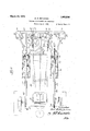
Figure 1 is a side elevation of the invention as applied to a common type of tractor;
and
Figure 2 is a similar plan view. l In the present instance the invention is illustrated as including a tractor of a type havin a comparatively narrow longitudinal body rame 10 supported on rear axle structure 11 including widely spaced traction 1926. Serial No. 125,855.
wheelsadapted to span two plant rows. The forward end of the body 10 issupported on a single centrally positioned steering truck l2. `These 'parts are shown in dotted lines on the drawings. The steering truck includes an upright steering postl journaled in a front cross member on the tractor frame, and the truck is steered through gearing 14 which transmits movement of the steering wheel and rod 15 to a' gear sector 16 on the upper end of the standard of the steering truck.
On the forward corners of the tractor frame at each side of the steering post suit-k able supporting brackets 17 arek provided. These bracketsY cooperate with coupling elements carrying pivotally mounted forwardly extending supporting arms 18. These arms extend horizontally and at their forward ends are pivoted in clamp brackets 19 supporting a transversely extending frame member 20 which' projects laterally beyond 211 which may be vswung into allgnment with bar 2l and carries a pin on its under side adapted to engage in an opening 25 in bar 21, thereby locking the arms 18 and member 20 against lateral movement when desired. As one preferred means for shifting the member 20 during operation of the implement, if that is desired, there is provided a forwardly projecting arm 26 which is connected to the vertical standard of the steer- `ing truck and shares its movement. The outer end of this arm is connected as by a' link 27 to an arm 28 on one of the clamp brackets 19. By this arrangement, steering movement of the truck will be communicated to the member 20 to shift it in the direction of steering movement, which movement is limited by the llength of the slot 23 in arm 21. The supporting and shifting The extent of such lateral movemechanism for the frame bar 20, above dey scribed, may be of substantially the construe l29 on each of its projecting ends, which pairsA of members are arranged to straddle adjacent plant rows, which inl thisinstance are also straddled by the rear traction wheels of the tractor on which the planter attachment is mounted. Each pair of depending arms known type. Each planter unit is also pro-l 29 carries an arched crank member 30 which has horizontally extending angular portions pivoted in the .lower ends of the arms 29 'and an upwardly extending forwardly inclined arched portion, the upper portion 30 of which may swing in the space between the arms. The angular portions of the arch members 30 include transversely extending portions forming bearings for dragbars 31, the rear ends of which are fixed tofframes 32 carrying planter units.` These units are shown in this instance as comprising the usual seed hopper and dispensing mechalnism 33 mounted at the center of the frame 32, which frame is supported at its rear on adjustable covering wheels 34 journaled in brackets 35, which are pivotally connected to the frame 32 and adjustable in the usual `manner by means of the lever 36. The forward end of the frame 32 at its point of connection with the dragbars 31 is supported on a wheel 37, and this wheel may be connected to the dispensing mechanism by a double crank and pitman construction 38 of well vided with the necessary furrow openers herein shown as twin disks 39. As means for lifting and lowering each planting unit and thereby governing its operation, there is provided a lift operating rod 40, the forward end of which is pivotally connected to the-arched portion 30a of the arched members 30. 4The rear end of this rod 40 is connected to a lever 41 which is4 pivoted on 'a bracket 42 provided with a locking rack for lever 41l and having means for connecting it to the rear axle structure of a tractor. At a proper point in its forward portion the oppratingI rod carries a bracket 43 to w ich is pivoted the upper end of a lifting yoke 44, the arms of which are' pivotally connected at 45 to the sides of the planter frame 32.- With this arrangement,- when the lever 41 is swung, the rod 40 will be given longitudinal movement and the archedmembers 30 glven arcuate movement, theA range of which is indicated in dotted lines on Figure 1, thereby causing up and down move-` ments of the liftincf yoke 44 and planter unit in a substantially arallel manner, as also indicated in dotted lines on Figure 1.
It Vwill be evident that the construction described results in a simple structure for providing a tractor of standard type with planting units positioned at its sides where they are under observation of the operator at his station on the rear of the tractor and that the attachment through the operatingy rods 4() and levers 41 provides means Whereby the units can be raised and lowered to bring them out of or into operating position. It will also be clear that the frame member 20 may be allowed to have lateral movement, if desired, and that this movement will be transmitted through the, steering mechanism, thereby causing the; planter units to share in the steering movement of the tractor. It will-be understood, however, that member 20 may be locked against lateral movement and the arm 26 disconnected from the steering standard 13 in which case the steering of the tractor will not ai'ect the planter units.
While the construction above described exemplifies onepreferred form of the invention, it willbe obvious to those skilled in the art that certain modifications in the structure are possible without departingv from the scope of the invention as defined in the following claims.
What is claimed as new is:
l. The combination of a self-propelled Vehicle having a longitudinal body frame,
traction and steering means supporting oposite ends ofthe frame, a carryingy memer extending across the front end of the body frame and projecting beyond it at each side, planter units positioned to trail at each side of the body frame and each having ground wheels normally supporting the unit,
draft connections including means carried by the projecting ends of the carrying member lfor bodily lifting and lowering the planter units while maintaining said units in. parallel relation to the ground surface, and means operable from a station on the vehicle for actuating the lifting and lowering means.
2. The combination comprising a selfpropelled vehicle having a longitudinal body frame, traction and steering means supporting the opposite ends of the frame, planter units positioned to trail vat each side of the body frame and each having ground wheels normally supporting the' unit, draft connections carried by the forward vportion of the body frame and connected thereto by laterallyshiftable means including means for bodilylifting and loweringthe planter units, and actuating means for the lifting and lowering means and for thel laterally shiftable carryingmeans operable from a station on the vehicle.
" 3. The combination of a self-propelled vehicle comprising a rear axle housing having an operators station thereon and suported at its ends on traction wheels and a ody frame extending centrally from said me v 1,eea,aso
housing and supported on a steering truck, planter units located on 'each side of the body frame in advance of the axle7 said units having horizontal frames having supporting Wheels at the front and rear7 means connecting each planter unit to the body frame' including vertically shiftable draft members connected to each unit at longitudinally spaced points on the frame, and means operable from theoperators station for shifting said supports to bodily raise and lower the planter units While maintaining the frames in parallel relation to the ground surface.
4. The combination of a self-propelled vehicle comprising a rear axle housing having an operators station thereon and supported at its ends on traction Wheels and a body frame extending centrally from said housing and supported on a steering'truck, planter units located on each side of the body frame and truck and in advance of the `axle Within the treads of the traction wheels,
supporting Wheels individual to each planter i unit, means for actuating the units from certain of said wheels, combined draft and lifting means connecting each unit to the body `frame, and means operable from the operators station for. actuating the lifting means.
In testimony whereof aiiix my signature.
BERT R. BENJAMIN.
Priority Applications (1)
| Application Number | Priority Date | Filing Date | Title |
|---|---|---|---|
| US125855A US1663236A (en) | 1926-07-30 | 1926-07-30 | Planter attachment for tractors |
Applications Claiming Priority (1)
| Application Number | Priority Date | Filing Date | Title |
|---|---|---|---|
| US125855A US1663236A (en) | 1926-07-30 | 1926-07-30 | Planter attachment for tractors |
Publications (1)
| Publication Number | Publication Date |
|---|---|
| US1663236A true US1663236A (en) | 1928-03-20 |
Family
ID=22421746
Family Applications (1)
| Application Number | Title | Priority Date | Filing Date |
|---|---|---|---|
| US125855A Expired - Lifetime US1663236A (en) | 1926-07-30 | 1926-07-30 | Planter attachment for tractors |
Country Status (1)
| Country | Link |
|---|---|
| US (1) | US1663236A (en) |
Cited By (1)
| Publication number | Priority date | Publication date | Assignee | Title |
|---|---|---|---|---|
| US2417931A (en) * | 1943-12-23 | 1947-03-25 | Int Harvester Co | Tractor mounted planter |
-
1926
- 1926-07-30 US US125855A patent/US1663236A/en not_active Expired - Lifetime
Cited By (1)
| Publication number | Priority date | Publication date | Assignee | Title |
|---|---|---|---|---|
| US2417931A (en) * | 1943-12-23 | 1947-03-25 | Int Harvester Co | Tractor mounted planter |
Similar Documents
| Publication | Publication Date | Title |
|---|---|---|
| US2195631A (en) | Plow | |
| US2171031A (en) | Tractor implement | |
| US2362728A (en) | Agricultural implement | |
| US1831997A (en) | Plow | |
| US1663236A (en) | Planter attachment for tractors | |
| US2221769A (en) | Tractor attachment | |
| US2190359A (en) | Tractor attachment | |
| US2337749A (en) | Tractor-mounted implement | |
| US1760128A (en) | Farm-implement attachment for tractors | |
| US1940992A (en) | Implement attachment for tractors | |
| US2144347A (en) | Lister | |
| US2172983A (en) | Implement lifting mechanism | |
| US2010110A (en) | Self-propelled planter | |
| US2071118A (en) | Cultivator attachment for tractors | |
| US2194202A (en) | Ground working implement | |
| US1946402A (en) | Cultivator | |
| US2032085A (en) | Cultivator | |
| US2136640A (en) | Adjusting mechanism for tractor implements | |
| US1878871A (en) | Tractor operated planter | |
| US1958625A (en) | Cultivator | |
| US2072139A (en) | Cultivator attachment for tractors | |
| US1819679A (en) | Tractor lister attachment | |
| US1718773A (en) | Tractor cultivator | |
| US1755806A (en) | Tractor cultivator | |
| US1704929A (en) | Power-lift implement |