US1663230A - Electromechanical telephone system - Google Patents
Electromechanical telephone system Download PDFInfo
- Publication number
- US1663230A US1663230A US19556A US1955625A US1663230A US 1663230 A US1663230 A US 1663230A US 19556 A US19556 A US 19556A US 1955625 A US1955625 A US 1955625A US 1663230 A US1663230 A US 1663230A
- Authority
- US
- United States
- Prior art keywords
- brushes
- contact
- brush
- contacts
- relay
- Prior art date
- Legal status (The legal status is an assumption and is not a legal conclusion. Google has not performed a legal analysis and makes no representation as to the accuracy of the status listed.)
- Expired - Lifetime
Links
- 230000001276 controlling effect Effects 0.000 description 39
- 238000004804 winding Methods 0.000 description 36
- 238000009413 insulation Methods 0.000 description 6
- 238000005476 soldering Methods 0.000 description 3
- 239000002184 metal Substances 0.000 description 2
- 241000125205 Anethum Species 0.000 description 1
- 235000016936 Dendrocalamus strictus Nutrition 0.000 description 1
- 238000010586 diagram Methods 0.000 description 1
- 230000000694 effects Effects 0.000 description 1
- 230000002452 interceptive effect Effects 0.000 description 1
- 238000006263 metalation reaction Methods 0.000 description 1
- 230000002093 peripheral effect Effects 0.000 description 1
- 229920000136 polysorbate Polymers 0.000 description 1
- 230000002035 prolonged effect Effects 0.000 description 1
Images
Classifications
-
- H—ELECTRICITY
- H01—ELECTRIC ELEMENTS
- H01H—ELECTRIC SWITCHES; RELAYS; SELECTORS; EMERGENCY PROTECTIVE DEVICES
- H01H67/00—Electrically-operated selector switches
- H01H67/02—Multi-position wiper switches
- H01H67/04—Multi-position wiper switches having wipers movable only in one direction for purpose of selection
- H01H67/06—Rotary switches, i.e. having angularly movable wipers
Definitions
- FRITZ ALDENDORFF OF BERLIN-WILMERSDORF, GERMANY; CHARLOTTE ALDEN- DORFF, HEIRESS OF FRIEDRICH ERNST ALDENDORFF, DECEASED.
- This invention relates to electro-mechanically controlled systems and an object of the invention is to provide a system in which calling subscribers can operate their impulse sending dials or transmitters very rapidly without thereby interfering with the accuracy of operation of the selectors
- Another object of the invention is to provide a selector that can be used as a numerical switch or as a non-numerical switch that is capable of finding any one of a large number of lines or trunks in a fraction of a second without necessitating the employment of a plurality of simultaneously hunting wipers or brushes.
- a further object of the invention is to pro vide a type of selector with a large number of bank contact sets, say 100 sets, that can be connected in multiple with similar bank contact sets of other selectors by piano wiring.
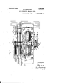
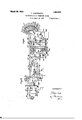
- Fig. 1 is a front View
- Fig. 2 a plan view
- Fig. 3 a cross section of Fig. 1 on the line IIIIII.
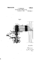
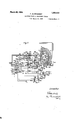
- Fig. 4 shows the multiple piano wiring of bank contact sets of three switches according to the invention.
- Fig. 5 shows the circuits of a line-finder
- Fig. 6 the circuits of a group selector
- Fig. 7 the circuits of a connector in a 1000 line exchange equipped with rotary 100 point switches according'to the invention.
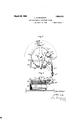
- Figs. 8 and 9 show a top viewand a side view of a modified selector in which the brush setting and spring rewinding operations-and the resetting of the switch to its normal position are all performed by one and the same elec-' iromagnet.
- the selector provided with eight arcuate bank contact rows. There may be 50 individual contacts in each row embedded in a semi-circular strip of insulation consisting of bakeliteor the like.
- the eight semi-circular strips are fixed by screws 9 and by an arcuate plate 10 on a lower arcuate plate 11.
- the lower arcuate plate 11 terminates at both ends in downwardly bent lateral plates 12, 13 to which is fixed the frame 14 by means of four screws 15.
- the screws 15 pass through hollow screws 16 whose external threads fit into female screws in the plate or frame 14.
- the frame 14 supports the magnets 17 18 and all the movable parts of the selector.
- the selector brushes a, Z), c a 5 0 d, e have square holes at the middle or at their ends by which they are threaded onto a tubular member 19 of square cross section.
- the metal at the edges of the four cornered holes of the brushes is struck up or bent over at right angles so as to present a blunt surface to the insulation inserted between a tubular member and the edges of the holes of the brushes. By this means the edges of the holes of the brushes are prevented from cutting into the insulation.
- the brushes are separated from each other by interposed washers of metal and insulation and are pressed down and firmly held together by a nut 20 and a shoulder 21 at the bottom end of the tubular member 19.
- the tubular member is fixed, as by a transverse pin to an internal shaft 22.
- a toothed wheel 23 is fixed by screws to the shoulder 21 ofthe tubular member 19.
- the shaft 22 to which the wheel 23 and the brushes are fixed revolves in a hollow shaft 24 on which is fixed a spring winding wheel 25 of smaller diameter than the wheel 23.
- the hollow shaft 24 is journalled in a bottom bearing 26 and an upper bearing 27
- the bearings 26 and 27 are fixed to the rear of the frame or plate 14.
- the top bearing consists of a bracket 27 into which is screwed a threaded bushing 28 that has a hexagonal head by which it can be screwed up and down to adjust the height of the brushes.
- the hollow shaft 2 L bears upon the hexagonal head of the threaded bushing 28 through the hub 29 of an arm 30 that is fixed to the top end of the hollow shaft 24.
- the wheel 23 and the pin The one end of the spring 33 in the spring box is fixed to the peripheral wall of the spring box and therefore to brush shaft 22, while the other end of the s ring 33 is fixed to the hollow shaft 24: that carries the smaller springwlnding wheel 25. There fore, it the toothed wheel 23 fixed to the brush shaft 22 is held.
- the spring 3 of the spring box rotates the brush shaft t set a set of brushes, e. g. a 5 0 onto an desired set of bank contacts, e. g. e 6 0
- the brushes are rotated. in the same direction until they reach their normal. position in which the brush a rests upon the bard: con tact a
- the arresting pawl 53% is withdrawn from the wheel 23 by the magnet 1?
- the toothed wheel 23 is however not released again hereby because at the moment when the edge 48 struck the arresting member 46, or shortly before, the magnet 17 was deenergized by the opening of a contact 51 so that this magnet allowed the detent 35 to reengage with the toothed wheel 23.
- the winding magnet 38 is deenergized by the e ching of another contact 52 at the moment in which the arm 30 raises the arresting member 56 from the toothed wheel 23.
- the contact 51 is controlled by a disk 53 fixed on the shaft 22 and provided with a notch 55 into which one of the springs 5i enterswhen or shortly before the brushes reach their normal position.
- the contact s .igs 52 are controlled bv a similar dish 54 hired to the hollow short 24.
- the bancontacts are shapes so that the tabs 68 to 75 lie .11 one and. the some 1' .tl plane or project out from the insulation in which they are embedded in the same radial direction, but bend laterally at different distances from the periphery of their strips oi insulation l-8 so to enable the wires 76-83 that are soldered to the tabs to extend past their edges without contacting with them.
- the bare wire 76 soldered to the short tab T5 is enabled to extend past the lateral edges of all the longer soldering tabs 68-7-il and to effect a connection with the corresponding shortest soldering tabs 75, 75 of the other selectors without touching any of the longer soldering tabs.
- the contact sets oi": dill'ere selectors are all interconnected by a group oil: bare wires 76-83 that lie one behind the other in a radial plane.
- the brushes that wipe over the baul; contacts are arrai d on a nightly different plan in the di erent '1 of selectors (linefinders, group selectcs connectors).
- the connectors are provided with two sets of three brushes c Z), c and a b
- the brushes (1, 5 .0 only cooperate t contacts of the top three arcuate rows -whi the brushes (a 5 c coopera e with fourtln fifth and sixth arcua e r l the setting of the sets of brushes o, c and a 7?
- the group selectors have two sets of brushes 0, b, 0 and (1,, b 0 which are axially displaced on their shaft in the same way as the brushes of the connectors.
- the setting of the brushes of a group selector onto the proper groups of bank contacts is effected by a single two-ended brush a, as indicated diagrammatically in Fig. 6.
- the brush a wipes alternately over short and long bank contacts while the other brushes wipe over short bank contacts only.
- the reasons for this arrangement will appear hereinafter in the description of the operations of the circuits.
- the line-finders each have two sets of axially displaced brushes similar to the sets of brushes a, b, c and 00,, b 0 except that there is an additional brush (6,, Fig. 5) in each set. All the brushes of the line-finders are single-ended and each brush wipes over 50 bank contacts.
- the fourth brush, 6,, Fig. 5, of each set of brushes controls the setting of the brush set (1 b 0 onto the bank contact sets of calling lines.
- the subscriber T desires to establish a connection with a subscriber 772.
- a circuit for the line relay 100 is closed which extends from the negative pole of the battery through the line relay 100, contact 101 of the cut-off relay 103, wire 104, calling subscribers station '1, wire 105, contact 102 of the cut-off relay 103 to the positive pole of the battery.
- the relay 100 opens its contact 106 and thus renders the calling line engaged.
- the relay 100 disconnects the negative pole from the designating contacts 109 of the contact banks of all line-finders in the calling subscribers group, and at its contact 108 it closes a circuit for the relay 110 that extends from the negative pole, through 108, 111, relay 110 to the positive pole of the battery.
- the relay 110 closes at its contact 112, the circuit of the starting magnet 113 that corresponds to the magnet Consequently the brushes 0,, b 0,, e, are caused to travel at a high speed b the brush driving spring.
- the circuit 0 the starting magnet 113 extends from the positive pole through contact 114 of relay 115, 113, 112, contact 116 of relay 117, brush e through contacts like 107 to the bank contact set of the calling line,
- the armature of the magnet 113 falls back and engages with the toothed wheel connected to the brush carrier andthus stops the brushes.
- the falling back of the armature of the starting magnet 113 is acceler ated by the condenser 118 connected in parallel with the starting magnet winding.
- the relay 115 is now energized by a current that flows from the negative-pole through 119, 115, 0 cut-off relay 103 to the positive pole of the battery.
- the relay 115 shortcircuits a part of its winding by its contact 120, and the relay 103 separates the line 'relay 100 from the calling line and at its contacts 121, 122 it extends the calling line through the contacts 123, 124 of relay 115 to the impulse relay 200 of the group selector.
- the deenergized line relay 100 reconnects the negative pole through its contact 107 to the contact 109, but the magnet 113 is not energized hereby because the contact 114 has been opened by relay 115.
- the impulse relay 200 is now energized by a current that flows through the calling station T and by closing its contact 201 it energizes the release relay 203 which latter energizes the relay 117 by its contact 204.
- the latter relay opens its contacts 116, 111 and, by its contacts 131, it extends the finder starting wire 130 to the next idle line-finder and at the same time it closes a locking circuit for itself that extends through the contact 132 and the off-normal contact 133 which was closed when the brushes of the line-finder moved out of their normal positions.
- the relay 115 is now kept energized by a current that flows from the negative pole through 204, 120, left winding of 115, 0 103-to the positive pole and the potential on the test wire 134 is reduced to such an extent that the busy condition of the calling line is maintained.
- the calling subscriber now sends in a series of seven hundreds impulses.
- the change-over relay 207 is energized by a current that flows from the negative pole through 205, 208, 207 to the positive pole, and at contact 206 an energizing circuit is closed for the brush setting magnet 213 which is similar to magnet 17 in Figures 1 and 2.
- This energizing circuit extends from the negative pole through 206, 209, wire 210, the first short bank contact 214-, brush 6,, brush setting magnet 213, that is bridged by the condenser 211, to the positive pole.
- the magnet 213 attracts its armature and thereby releases the brushes so that the brush a, wipes over a long contact connected to the wire 219 and over contact 220 that is con nected to the negative pole. As long as the brush 6 touches the long contacts the magnet 213 remains energized. It is deenergized however as soon as it reaches the short intermediate contact 215. This shortv contact is connected to battery as soon as the impulse relay 200 reattracts its armature at the end of the first interruption in the series of hundreds impulses aforementioned. The magnet 213 then receives another impulse that flows from the negative pole through 221, contact 222, Wire 223, short intermediate contact 215, brush 0,, 213 to the positive pole.
- the magnet 213 by attracting its armature releases the brushes again and it remains energized by current flowing through the next long contact connected to the wire 219 until the brush 6, reaches the next short intermediate contact 216.
- the magnet 213 now lets its armature drop back and arrests the brushes until it is reenergized as a result of the second impulse in the series of hundreds impulses.
- This energizing current flows from the negative pole through 206, 209, 210, 216, 6 213 to the positive pole.
- the selector brushes now travel onto the next short intermediate contact 217, where they are again arrested until at the energization of the impulse relay a current impulse flows from the negative pole through 221, 222, 223, 217, 0 213 to the positive pole.
- the selector brushes are then rotated on to the 11 Kt short intermediatecontact 218 by the brush driving spring. It is thus seen that at each detraction and succeeding reattraction of the armature of the impulse relay the set of selector brushes executes two half or partial steps which amount to a single full step. Seven hundreds impulses cause the brushes to execute seven full or long steps. In er:- ecuting seven long steps a set of brushes completes one half of a revolution and then leaves the rows of arcuate bank contacts with which it cooperates while the other set oi brushes enters into contact with its coordinated bank contacts and executes two long steps thereover so that its brush ultimately stops on the contact 22% that lies between the groups oi bank contact sets g 9,. It is to be noted that the selector controlling brush a, has two ends, one of which reaches the arcuate bank contact row of short and long contacts the moment the other end leaves this contact row.
- the set of brushes a 6 0 having been s it onto the group of bans contact sets g, the change-over function now takes place in consequence of a prolonged energization of the impulse relay which causes the deener gization of the change-over relay 207.
- This relay 207 opens its contacts220, 222, and as the contact 206 or" the impulse relay 200 is now also open the wires 219, 223, 210 that are connected to the row of controlling bank contacts wiped by the brush a, are disconnected from the negative pole of the battery, so that the brush setting magnet does not receive any more brush setting or controlling impulses through the brush 6,.
- the brush setting magnet When the contact 226 is closed by the detraction of the armature of the change-over relay 207, the brush setting magnet is energized by a current that flows from the negative pole through the bank contact 225, brush a, relay 227, contact 228 of the energized release relay 203, 226, 213 to the positive pole.
- This current first causes the slowly detracting relay 227 to attract its armature so as to shortcircuit itself by its own contact 229 and thus cause the energization of the brush setting magnet by a current that flows from the negative pole through 225, 0 230, 231, 229, 228, 226, 213 to the positive pole.
- the brush setting magnet 213 opens its contacts 232, 233, closes its contact 234:, and before opening contact 230 it also, closes the con tact 235. At the same time the magnet 213 releases the brush carrier so that the brushes are driven by the driving spring at a high speed over the group of bank contact sets 9 until the brush 0 reaches a contact, such as 237, that is not connected to the negative pole. The brush setting magnet 213 is then deenergized so that its armature arrests the brushes. At the same time it extends the calling line through its contacts 232, 233 to the connector (Fig. 7) and opens its contacts 234, 235 while closing contact 230.
- the relay 227 was energized in the. manner described and by short-circuitmg its own winding immediately thereafter caused the energization of the brush setting magnet 213, the relay 239 was energized by a current that flowed from the negative pole through 238, 234i, 239 to the positive pole of the battery.
- the relay 239 closed at its contact 240 a locking circuit for itself and at its contact 231 severed the connection be tween contacts 230 and 229 so as to pre vent a renewed short-circuit of the relay when the brush setting magnet 213 was deenergized for the purpose or" arresting the brushes a 6 0
- the energization oi the impulse relay 300 of the connector talres place when the call ing subscribers line is extended as described through the brushes of the group selector.
- the release relay 303 is energized by a, current that flows from the negative pole through 305, 303 to the positive pole.
- the relay 227 in the group selector is then ener gized by a current that flows from the tive pole through 306, 237, 0 227, 228, 213 to the positive pole. Since, as already exlained, the Contact 231 is now open, the reay 227 does not now short-circuit itself when energized and the comparatively weak current flowing through it does not suflice to energize the brush setting magnet 2l3.
- the relay 227 at its contacts 242, 243 disconnects the impulse relay 200 from the voice current wires 250, 251 but closes contacts 244, 245 to prevent the deenergization of said impulse relay.
- the connector (Fig. 7) has two sets of three brushes each which are displaced axially and radially with respect toeach other and each of which has only one bank contact wiping end.
- the connector has two two-ended brushes or wipers.
- the two bank contact wiping ends of the brush that wipes over the arcuate row of short and long bank contacts are designated 6 and e, while the ends of the brush that wipes over the controlling bank contact row that contains short bank contacts only are designated d and d.
- the set of brushes a, b, c is shown in a position in which it has alreadyexecuted five long steps without wiping over any bank contacts and in which it is just commencing to execute its sixth long step.
- One end of each controlling brush has just wiped'over its row of controlling bank contacts and the other end of each brush (1, e is just starting to wipe over the same bank contact rows.
- the brush setting magnet 320 is kept energized by the long contact situated between the short contacts and connected through a resistance 321, wire 322, contact 323 to the positive pole, the contact 323 being closed by the energization of the changeover relay 324 due to the dialling impulses.
- the brush 6 rests on the short contact 315 at the beginning of the group of bank contact sets 9,.
- the impulse relay now remains energized for a comparatively long period so that the change-over relay 324, which was kept energized during the dialling impulses through the contacts 304, 326 allows its armature to drop back.
- the relay 327 is now energized by a current that flows from the negative pole through contact 328 of the oilnormal switch III, which is still closed, 1,, 329, upper winding of relay 327, contact 330 to the positive pole.
- the relay 327 at its contact 331 closes a locking circuit for itself that extends through contact 307 to the positive pole, while it disconnectsthe impulse wire 309 from the row of controlling bank contacts that is wiped by the brush 6, and by contact it connects the impulse wire 309 to the contact arm 332 of an auxiliary switch.
- the auxiliary switch has three contact arms 332, 334, 335 that are rotated step by step by a magnet 336 in such a manner that they execute a forward step at each detraction of the armature of their stepping magnet 336.
- the calling subscriber now sends in two units impulses, the first impulse flows from the negative pole through 307, 308, 333 to the contact arm 332, bank contact 337, bank contact 338 of the connector, control ling brush (Z, brush setting magnet 320 to the positive pole.
- control ling brush Z, brush setting magnet 320 to the positive pole.
- a part of the impulse flows through 333, wire 339, contact 340, magnet 3360f the auxiliary switch to the positive pole,so that this magnet tensions its armature spring.
- the impulse that flows through the bank contact 338 energizes the wiper setting magnct 320 so that this latter releases the connector brushes and the brush driving spring rotates them to the next bank contact 341 that has no connection with the negative pole, so that when it is reached by the controlling brush the brush setting magnet 320 is deenergized.
- the impulse relay 300 opens the contact 308 again after the first units impulse, the magnet 336 is deenergized and its detracted armature steps the contact arm 332 forward to the next contact 342that is connected to nector brushes and when the brush cZ reaches the contact 350, is gain deenersized so as to arrest the brushes a, Z), c on the bani: contacts oi the desired line No. 772.
- the change-over relay 324 which was lrept energized through 30%, 326 while the units dialling impulses were being sent now allows its armature to drop back and by contact 355' connects t re negative pole of the battery to the test relay 356, so that this relay is energized if the wanted line is free by a current that extends from the negative pole through 307, 357, oil-normal. contact 358 355, 356 0, test wire 359, armature relay contact of the wanted subscriber, similar to contact 10-3,
- the test relay closes a ringing current circuit its contacts 360, 361 so that intermittent ringing current now lows from the ringing current generator 363 through the contact arm 3341:, relay 36 i and contacts 365,
- the intermittent closing of the ringing current circuit is effected by the auxiliary switch whose magnet is connected in the circuit of the interrupter367 when the test relay 356 is energized.
- the circuit of the operating magnet 336 extends from the negative pole through the interrupter 367, wire 368, relay contact 369, contact 370, magnet to the positive pole.
- the ringing current generator 363 sends ringing current to the wanted subscriber.
- the current flowing through the relay sea is strengthened so that this relay closes at its Contact 372 an energizing circuit for the relay 373 that extends from the positive pole through 372, left- Winding of 373 to the negative pole.
- the relay By its contacts 374, 375 the relay new extends the calling line to the wanted line'and its contacts 365, 366 it cuts off the ringing current.
- the relay 373 opens the circuit of relay 327 and this latter-now prepares at its contact 377 a circuit which, when the wanted subscriber replaces his receiver, is established from the negative pole through 378, 377, 380, 379 to the positive pole so that the relay 379 at its contact 381 cuts off the impulse relay 300 andthus initiates the release of the connector.
- the connector is also released it the calling subscriber replaces his receiver first and thus causes the deenergization of the impulse relay 300.
- the circuit of the release relay 303 is opened at contact 305 and at contact 382 the brush setting magnet 320 of the connector is connected in a cuit that extends from the negative pole through 332 oil-normal contact I, 320 to the positive pole.
- the magnet 320 attracts its armature to release the brush carrier and the brushes are now turned into their normal position by the brush driving spring. v fhen they reach their normal position the off-normal l is opened and the brush setting magnet 320 is thus deener'gized.
- the spring winding magnet 333 received current impulses in a circuit extending from the negative pole through 307, 38%, 383 to the positive pole.
- the off-normal contact 11 that cooperates with the hollow shaft of the selector wasclosed so that when the release relay 303 deenergized current impulses flow from the negative pole through 385, II, 333 to the positive pole.
- the winding magnet new steps the small toothed wheel of the selector and the hollow shaft round until the spring is fully rewound. As soon as this is ei'l'ected the off-normal contact 11 is opened 1 interrupts the circiiit oi the winding 1st 333.
- ie contact arms 332, 334, 335 of the auxiliary switch whose contact arm 335 rests on the arcuate contact 385 are returned to their normal position by current impulses that tlow om the negative pole through the interrupter 367 385, arcuate contact 385, contact a n 335 magnet to the positive pole. Then the contact arms of the auxiliary switch reach their normal position the contact arm leaves the arcuate contact 385 and stops the current impulses flowing through the magnet 336. The connector is thus returned to its normal position.
- the restoration of the group selector is initiated by the opening of the circuit of relay contact 306 of the release relay 303 of the connector.
- the impulse relay 200 oi the group selector is reconnected with the trunk 250, 251 and when the calling subscriber replaces his recciver the circuit of the release relay 203 is opened at contact 201 and at contact 260 of the release relay the brush setting magnet 213 is connected ina circuit that extends from the negative pole through 1 relay con tact 260, 226, 213 to the positive pole.
- the energized brush'setting magnet 213 new releases the brush carrier and the brush driving spring rotates the brushes forward into th lr normal position in which the off-normal switch is opened to deenergize the magnet 21.3 and thus arrest the brushes.
- test relay 115 is deenergized and at its contact 166 establishes an impulse circuit through the spring winding magnet 163 that extends from the positive pole through the interrupter 165, winding magnet 163, 166, 167, contact 133 to the negative pole.
- the winding impulse circuit is interrupted by the off-normal contact 133 when the spring is completely rewound.
- the brushes are restored to their normal position by the closure of the circuit 'of the brush setting magnet 113 at contact 114. This circuit extends from the positive pole through 114, contact 169, off-normal contact I to the negative pole.
- the winding impulse circuit of magnet 113 is opened at the off-normal contact 1,. All parts of the exchange used for the connection have now been restored to their normal position.
- test relay 356 If the wanted subscriber is found busy the test relay 356 is not energized by the current that flows from the negative pole through 307, 357, 358, 355, 356 and brush 0.
- the calling subscriber then receives a busy tone that is produced by a busy tone current emanating from the coil 390 and passing through contact 391, brush 334, condenser 392, contact 365, contact 393, condenser 394, winding 395 of relay 373 to earth.
- the tone currents in winding 395 induce alternating currents in the winding of relay 373 and these currents produce a busy signal in the calling subscribers receiver.
- the calling subscriber then replaces his receiver whereby the impulse relay 300 in the connector and the impulse relay 200 in the group selector are deenergized and the restoring functions, already described, are initiated.
- a calling subscriber is connected through a group selector in a few hundredths of a second or even faster, while the extension of a connection through the group selector, after its brushes have been set by the dialling impulses, is also effected in about one hundredth of a second.
- the one end'of the spring in the spring box is connected to the wheel 2 and the other to the shaft 5.
- the spring in the spring box 10 is wound. Backward rotation of the wheel 2 is prevented by a detent 11.
- the two ratchet wheels 1 and 2 are controlled by the armature 12 of the electromagnet 13.
- the armature 12 is arranged to oscillate about a pivot 14 so that the arresting pawl 15 is swung to and fro in a radial line through the center of the shaft 5, while the end of the arm 16 oscillates in a tangent of the wheel 2*.
- the selector is returned to its normal position by again energizing the electromagnet 13
- the ratchet wheel 1 is now rotated forward by the brush driving spring until a projection 19 on the wheel strikes against a stop 20
- a projection (not shown) closes a switch which now sends current impulses through the electromagnet 13.
- the armature 12 is thus oscillated round its pivot 14 thereby oscillating the spring winding pawl 17 which steps the spring winding wheel 2 in the direction of the arrow. This rotation continues until a cam 21 on the wheel .2 lifts the movable stop 20* and at the same time interrupts the impulses flowing through the electrolnagnet 13.
- the detent 15 will drop into a recess between two teeth of the wheel 1 at the moment the spring winding impulses are interrupted so, thatthe rotation of the wheel 1 is prevented at the moment the stop 20 is lifted.
- the electromagnet 13 is energized again for new connection the wheel 1 and the brushes are then again whirled round by the spring until the desired line or trunk is reached.
- the auxiliary switch with the contact arms 832, 334;, 335 in Fig. 7 can be replaced by a relay which alternately connects the wire 339 to the groups of contacts wiped by the brush (5.
- Thisrelay is provideo with a winding that is connected to one of these contact groups and to a front contact i m pulse relay 307. it has a second loclnng winding which when the relay is energized is connected to the back contact of the impulse relay.
- the impulse relay energized the first winding of the said circuit changing relay is energized in a circuit that extends through the brush setting magnet 320 of the connector.
- the resistance of the winding of the circuit changing relay is such that the energization of the brush setting magnet is prevented at this time so that the circuit changing relay alone is energized.
- the impulse relay now allows its armature to drop back the wire 339 is connected through contact of the circuit changing relay to the brush set-ting magnet and this latter is energized that the brushes oi: the connector execute a short step and thus open the circuit through the energizing winding ot' the circuit changing relay.
- W hen the impulse relay is new again energized the loclringwinoing of the circuit changing relay is also opened and this relay now connects the wire 389 to the other group of banlr contacts wiped by the brush d.
- a switch having brushes and sets of bank contacts, means tor driving said brushes in a continuous motion over a plurality of said contacts, means including a brush setting magnet for setting said brushes onto any desired set of bank con tacts, and a switching device for connecting said brush setting magnet alternatelyto diitfercnt sets of bank contacts.
- a switch having brushes and sets of bank contacts, means for driving said brushes in a continuous motion over plurality of said contacts, means including a brush setting magnet for setting said Us telephone system, a plurality of telephone ines, a switch having brushes and sets of bank contacts, means including a brush setting magnet for setting said brushes onto any desired. set of bank contacts, a condenser connected in parallel with said magnet, contacts controll d by said magnet for extending one of said lines through said switch, and a switching device for connecting said brush setting magnet alternately to different sets of bank contacts.
- a switch having brushes inc sets of bank contacts, means including a brush setting magnet for setting said brushes onto any desired set oi-banlr contacts, a spring for driving said brushes in a continuous motion over a plurality of said sets of contacts under the control of said magnet, an electric circuit for winding up said spring, and a contact in said circuit closed as long as the switch is in an oft-normal position.
- a switch having brushes sets or" haul; contacts, means including a brush setting magnet for setting said brushes onto any desired set of ban-l; contacts, a spring for driving said brushes in a continuous motion over a plura ity of said setsoi? of contacts under the control oi said magnet, an electric circuit for winding up said spring, means for sending numerical impulses to said switch from a distant point, and means responsive to the sending of said impulses for closing said circuit.
- switch comprising a rotary brush carrier, plurality of arcuate contacts, sets of brushes CllSu rows of bank placed axially and angularly with respect to each other on said brush carrier, each set of brushes cooperating with a said arcuate row of bank contacts, a spring for rotating said brush carrier, a brush setting magnet for controlling the movements of said brushes, and controlling circuits for the said magnet which extend through bank contacts and a brush or brushes of said switch.
- a numerical switch com prising a rotary brush carrier, a plurality of arcuate rows of bank contacts, sets of brushes displaced axially and angularly with respect to each other on said brush carrier, each set of brushes cooperating with a, said arcuate row of bank contacts, a spring for rotating said brush carrier, a brush setting magnet for controlling the movements of said brushes; and means for controlling long steps of said brushes, said means comprising interconnected bank contacts, one of which is situated at the beginning of each group of bank contact sets and other interconnected bank contacts one of which is situated at or near the. middle of each group of bank contact sets, a numerical impulse receiving relay, and means for connecting an armature contact of said relay alternately to said sets of interconnected bank contacts.
- a numerical switch comprising a rotary brush carrier, a plurality of arcuate rows of bank contacts, sets of brushes displaced axially and angularly with respect to each other on said brush carrier, each set of brushes cooperating with a said arcuate row of bank contacts, a spring for rotating said brush carrier, a brush setting magnet for controlling the movements of said brushes, means for controlling long steps of said brushes, said means comprising interconnected bank contacts one of which is situated at the beginning of each group of bank contact sets and other interconnected bank contacts one of which issituated at or near the middle of each group of bank contact sets, a numerical impulse receiving relay, means for connecting an armature contact of said relay alternately-to the said sets of interconnected bank contacts, and long bank contacts located between said bank contacts at the middle and beginning or end of each group of bank contact sets.
- a numerical switch comprising a rotary brush carrier, a'plurality of arcuate rows of bank contacts, sets of brushes displaced axially and angularly with respect to each other on said brush carrier, each set of brushes cooperating with a said arcuate row of bank contacts, a spring for rotating said brush carrier, a brush setting magnet for contolling the movements of said brushes; and means for controlling long steps of said brushes; said means comprising interconnected bank contacts one of which is situated at the beginning of each group of bank contact sets and other interconnected bank cont-acts one of which is situated at or near the middle of each group of bank contact sets, a numerical impulse receiving relay, and further means for controlling short steps of said brushes, said further means comprising two sets of interconnected bank contacts each of which is associated with the set of bank contacts belonging to a certain line, and means for connecting an armature contact of said relay alternately first to the sets of interconnected bank contacts for controlling long steps of the brushes and then to the sets of interconnected
- arcuate rows of bank contacts arcuate rows of bank contacts, a rotary brush carrier, single-ended brushes angularly and axially displaced on said brush carrier and adapted to cooperate alternately with different arcuate rows of bank contacts, a brush with a plurality of ends each of which cooperates with the same arcuate row of bank contacts, a spring for rotatingsaid brushes, a brush setting magnet for controlling the movements of Said brushes, and energizing circuits for said magnet which extend through said mu tiended brush and the bank contacts with which it cooperates.
- arcuate rows of bank contacts arcuate rows of bank contacts, a rotary brush carrier, single-ended brushes angularly and axially displaced on said brush carrier and adapted to cooperate alternately with different arcuate rows of bank contacts, a brush with a plurality of ends each of which cooperates with the same arcuate row of'bank contacts, a spring for rotating said brushes, a brush-setting magnet for controllinglong step group selecting movements of said brushes, and energizing circuits for said magnet.
- arcuate rows of bank contacts arcuate rows of bank contacts, a rotary brush carrier, single-ended brushes angularly and axially displaced on said brush carrier and adapted to cooperate alternately with different arcuate rows of bank contacts, multi-ended brushes each of which cooperates with an arcuate row of bank contacts, a spring for rotating said brushes, a brush-setting magnet for controlling long-step and short-step movements of said brushes, and energizing circuits for,
- a selector with two coaxial shafts interconnected by a shaft driving spring, brushes carried in a continuous motion over a plurality of bank cont-act sets by the spring driven shaft, a toothed wheel fixed onthe brush carrying shaft, bank contacts wiped by said brushes, and an electromagnet with an armature that stops said toothed wheel and brushes when the latter reach a bank contact connected to an electrical brush stopping potential.
- a selector with two coaxial shafts interconnected by a shaft driving sprin brushes carried by the spring-driven shaft, a toothed brush stopping wheel fixed. on the brush carrying shaft, a toothed spring winding wheel which is of smaller diameter than v the brush-stopping wheel and,
- spring, brushes carried in a continuous motion over a plurality of bank contact sets by the spring driven shaft, a unidirectionally rotated toothed wheel fixed on the brush carrying shaft, bank contacts wiped by said brushes, and an electromagnct with an armature that stops said toothed wheel and brushes when the latter reach a ban k contact connected to an electrical brush stopping potential; 7 it).
- a selector with two coaxial shafts interconnected.
- a switch comprising a row of bank contacts, a brush, a power device for moving said brush in a continuous motion over a plurality of said contacts, a brush setting magnet for stopping the brush at desired contacts, an electrical connection which interconnects a group of said contacts, a second electrical connection which interconnects a second group of said contacts, a contact of the second group following after e 'ch contact of the first group in the row, energizing circuits for said magnet, and a switching device for closing said energizing circuits through said brush setting magnet, said brush, and through said first and second electrical connections alternately.
- a main switch comprising a row of bank contacts, a brush, a power device for moving said brush over said con tacts, a brush setting magnet for stopping the brush at desired contacts, an electrical connection which interconnects a group of said contacts, a second electrical connection which interconnects a second group of said contacts, a contact of the second group following after each contactof the first group in the row, an auxiliary switch comprising a row of fixed contacts, a brush, a magnet for moving said brush step-by-step over said.
- a switch comprising a row of controlling bank contacts, a controlling brush that wipes over the controlling bank contacts, rows of talking current bank contacts, talking current brushes that wipe'o'ver the talking current bank contacts, a power device for moving said.
- a switch comprising a row of bank contacts, a brush, a power device for moving said brush over said contacts, a brush setting magnet for stopping the brush at desired contacts, a condenser for quickening the operation of said magnet, an electrical connection which interconnects a group of said contacts, a second electrical connection which interconnects asecond group of said contacts, a contact of the second group following after each contact to the first group in the row, energizing circuits for said magnet, and a switching device for closing said energizing circuits through said brush set-ting magnet, said brush, and through said first and second electrical connections alternately.
- a switch comprising a row of bank contacts, a brush, a spring for moving said brush in a continuous motion over a plurality of said contacts, a brush setting magnet for stopping the brush at desired contacts, an electrical connection which interconnects a group of said contacts, a second electrical connection which interconnects a second group of said contacts, a con tact of the second group following after each contact of the first group in the row, energizing circuits for said magnet, and a switching device for closing said, energizing circuits through said brush setting magnet, said brush, and through said first and second electrical connections alternately.
- a switch comprising a row of bank contacts, a brush, a spring for moving said brush in a continuous motion over a plurality of said cont-acts, a brush setting magnet for stopping the brush at desired contacts, an electrical connection which interconnects a group of said contacts, a second electrical connection which intercon nects a second group of said contacts, a con tact of the second group following after each contact of the first group in the row, energizing circuits for said magnet, a switching device for closing said energizing circuits through said brush setting magnet, said brush, and through said first and second electrical connections alternately, and clectrically controlled means for rewinding said spring after it has operated said brush.
- a switch comprising a row of primary controlling bank contacts, a row of secondary controlling bank contacts, a primary controlling brush that cooperates with the primary controlling bank contacts, a secondary controlling brush that cooperates with the secondary controlling bank contacts, a power device for moving said brushes, a brush setting magnet for stopping the brushes first at a desired group of bank contacts and then at a desired contact in a group, an electrical connection which interconnects a group of said primary controlling bank contacts, a second electrical connection which interconnects a second group of said primary controlling bank contacts, a contact of the second group of primary contacts following after each contact of the first group, energizing circuits for said magnet, a device for closing said energizing circuits through said brush setting magnet, said primary controlling brush, and through said first and second electrical connections alternately, and means for subsequently energizing said magnet through said secondary controlling brush and secondary controlling bank contacts.
- a switch comprising bank contacts, brushes adapted to glide in a continuous motion over a plurality of said bank contacts, a continually acting power device tending to move said brushes, one detent both for holding the brushes in an initial position against the action of said power and for positively stopping the powerdriven brushes on any desired bank contact, and an electromagnet for operating said detent.
- a switch comprising bank contacts, brushes adapted to glide in a continuous motion over a plurality of said bank contacts, a continually acting power device tending to move brushes, one dctont for holding the brushes in an initial position a ainst the action of said power device and for firstpositively stopping the power-driven brushes at a. plurality of points arranged at certain distances apart and for then positively stopping the brushes after they have travelled a shorter distance than the distance between two said points, and an electromagnet for operating said detent.
- a switch comprising bank contacts, brushes adapted to glide in a continuous motion over a plurality of said bank contacts, a continually acting power device tending to move brushes, one detent for holding the brushes in an initial position against the action of said power device and for first positively stopping the powerdriven brushes at a plurality of points arranged at certain distances apart and for then positively stopping the brushes at a plurality of other points placed closer together than the said first points, and an electromagnet for operating said detent.
- a switch comprising bank contacts, rotary brushes adapted to glide in a continuous motion over a plurality of said bank contacts, a continually acting power device tending to move said brushes, one detent for holding the brushes in an initial position against the action of said power device for positively stopping the powerdriven brushes on any desired bank contact and for finally stopping the brushes again in their initial position, and an electromagnet for operating said detent.
- a switch comprising bank contacts, rotary brushes adapted to glide in a continuous motion over a plurality of said bank contacts, a continually acting power device tending to move said brushes, one detent both for holding the brushes in an initial position against the action of said power and for positively stopping the power-driven brushes on any desired bank contact and for subsequently stopping the brushes again in their initial position, and an electromagnet for operating said detent.
- telc 'ihone In an electron'iechanically controlled telc 'ihone system, a switch comprising bank contacts, rotary brushes adapted to glide in a continuous motion over a plurality of said bank contacts, a continually actingpower device tending to move said brushes, one dotent for holding the brushes in an initial position against the action of said. power device and for first positively stopping the power-driven brushes at a plurality of points arranged a certain distance apart and for then positively stopping the brushes at a plurality of other points placed closer "together and for subsequently stopping the brushes again in their initial position, and an electromagnettor operating said detent.
- a switch comprising bank contacts, brushes adapted to glide over said bank contacts, a brush carrier, toothed member fixed to said brush carrier, a continuously acting power device tending to move said brushes, one detent that cooperates With said toothed member both for holding the brushes in an initial position against the action of said power and for positively stopping: the power driven brushes on any desired bank contact, and an electron'iagnet for holding said detent away from said toothed member while the brushes are moving.
- a switch comprising bank contacts, brushes adapted to glide over said bank contacts, a brush carrier, a toothed member 'lixed to said brush carrier, a co11- tinuously acting power device tending to move said brushes, one detent that cooperates with said toothed member both for nolding the brushes in an initial position against the action of said power and for positively stopping the power driven brushes on any desired bank contact, an electron'iagnetfor holding said detent away from said toothed member while the brushes are moving, and aco'ndenser for quickening the detaining action of said detent.
Landscapes
- Dc Machiner (AREA)
- Interface Circuits In Exchanges (AREA)
Description
' F. ALDENDORFF I ELECTROMECHANICAL TELEPHONE SYSTEI Filed March so. 1925 'r sheets-sheet 1 Inventor:
new WW.( 7
F. ALDENDORFF ELECTROMECHANIGAL TELEHIONE SYSTEM '7 Sheets-Sheet 2v Filed March so. 1925 March 20, 1928. 1,663,230
F. ALDENDQRFF ELECTROMECHANICAL TELEPHONE SYSTEI Filed March 30. 1925 '7 Sheets-Sheet 3 Fly-J:
Inventor:
March 20, 1928. 1,663,230
F. ALDENDORFF I ELECTROIECHANICAL TELEPHONE SYSTEM Filed March 30, 1925 '7 Sheets-Sheet 4 Invenior m lumlh I Fig. 4
March 20, 1928. 1,663,230
v F. ALDENDORFF BLECTROMECHANIGAL TELEPHONE SYSTEM Filed March 30. 1925 '7 Sheets-Sheet 5 InvenZor:
-com k 7 (M 1 March 20, 1928.
F. ALDENDORFF ELECTROMECHANICAL TELEPHONE SYSTEM Filed March 30, 1925 7 Sheets$heet 6 Inventor:
, 1,663,230 F. ALDENDORFF ELECTROMECHANICAL TELEPHONE SYSTEM Filed March 30. 1925 7 Sheets-Sheet 7 Patented Mar. 20, 1928.
UNITED STATES PATENT OFFICE.
FRITZ ALDENDORFF, OF BERLIN-WILMERSDORF, GERMANY; CHARLOTTE ALDEN- DORFF, HEIRESS OF FRIEDRICH ERNST ALDENDORFF, DECEASED.
ELECTROMECHANICAL TELEPHONE SYSTEM.
Application filed March 30, 1925, Serial No. 19,556, and in Germany April 3, 1924.
This invention relates to electro-mechanically controlled systems and an object of the invention is to provide a system in which calling subscribers can operate their impulse sending dials or transmitters very rapidly without thereby interfering with the accuracy of operation of the selectors Another object of the invention is to provide a selector that can be used as a numerical switch or as a non-numerical switch that is capable of finding any one of a large number of lines or trunks in a fraction of a second without necessitating the employment of a plurality of simultaneously hunting wipers or brushes.
A further object of the invention is to pro vide a type of selector with a large number of bank contact sets, say 100 sets, that can be connected in multiple with similar bank contact sets of other selectors by piano wiring.
Other objects of the invention will appear hereinafter and in the drawing.
The invention is illustrated in the drawing in which Fig. 1 is a front View, Fig. 2 a plan view and Fig. 3 a cross section of Fig. 1 on the line IIIIII. Fig. 4 shows the multiple piano wiring of bank contact sets of three switches according to the invention.
Fig. 5 shows the circuits of a line-finder, Fig. 6 the circuits of a group selector and Fig. 7 the circuits of a connector in a 1000 line exchange equipped with rotary 100 point switches according'to the invention. Figs. 8 and 9 show a top viewand a side view of a modified selector in which the brush setting and spring rewinding operations-and the resetting of the switch to its normal position are all performed by one and the same elec-' iromagnet.
Referring to Figs. 1 to 3 it will be seen that the selector provided with eight arcuate bank contact rows. There may be 50 individual contacts in each row embedded in a semi-circular strip of insulation consisting of bakeliteor the like. The eight semi-circular strips are fixed by screws 9 and by an arcuate plate 10 on a lower arcuate plate 11. The lower arcuate plate 11 terminates at both ends in downwardly bent lateral plates 12, 13 to which is fixed the frame 14 by means of four screws 15.
The screws 15 pass through hollow screws 16 whose external threads fit into female screws in the plate or frame 14. The frame 14: supports the magnets 17 18 and all the movable parts of the selector. The selector brushes a, Z), c a 5 0 d, e have square holes at the middle or at their ends by which they are threaded onto a tubular member 19 of square cross section. The metal at the edges of the four cornered holes of the brushes is struck up or bent over at right angles so as to present a blunt surface to the insulation inserted between a tubular member and the edges of the holes of the brushes. By this means the edges of the holes of the brushes are prevented from cutting into the insulation. The brushes are separated from each other by interposed washers of metal and insulation and are pressed down and firmly held together by a nut 20 and a shoulder 21 at the bottom end of the tubular member 19. The tubular member is fixed, as by a transverse pin to an internal shaft 22. A toothed wheel 23 is fixed by screws to the shoulder 21 ofthe tubular member 19. The shaft 22 to which the wheel 23 and the brushes are fixed revolves in a hollow shaft 24 on which is fixed a spring winding wheel 25 of smaller diameter than the wheel 23. The hollow shaft 24 is journalled in a bottom bearing 26 and an upper bearing 27 The bearings 26 and 27 are fixed to the rear of the frame or plate 14. The top bearing consists of a bracket 27 into which is screwed a threaded bushing 28 that has a hexagonal head by which it can be screwed up and down to adjust the height of the brushes. The hollow shaft 2 L bears upon the hexagonal head of the threaded bushing 28 through the hub 29 of an arm 30 that is fixed to the top end of the hollow shaft 24. The wheel 23 and the pin. The one end of the spring 33 in the spring box is fixed to the peripheral wall of the spring box and therefore to brush shaft 22, while the other end of the s ring 33 is fixed to the hollow shaft 24: that carries the smaller springwlnding wheel 25. There fore, it the toothed wheel 23 fixed to the brush shaft 22 is held. stationary while the wheel 25 on the hollow shaft 2% is rotated, the spring 33 in the spring box 31 can be wound up. lVhen the wheel 23 is then released it is whirled around with the shaft 22 and the brushes a high speed. The toothed wheel 23 is normally held by a detent 34 which is screwed onto an arm oi the armature 35 ot' the magnet 17. The wheel 25 on the hollow shaft E l is rotated to wind the spring 35 by a stepping pawl 3'7 pivoted to the end of the arm 38 oscillated by the armature 39 of the spring winding iagnet 18, which lattu' receives current impulses whenever the spring 33 is to be wound up. A detent lf) prevents backward rotation of the wheel 25. l he armatures 36, 39 of the magnets 35, 38 inane one arms tegral therewith are exactly similar in shape and so are magnets 17 and 18. When the arinatures 36., 89 are attracted they produce mechanical tension in springs all, 42. The tension of the springs can be adjusted by screws e3, i l. i l hen the magnet 17 allows its armature to drop back the spring 4i throws the arresting tooth 3% into engagement with a tooth oi? the brush stopping wheel 23 and thus stops the brushes on a set of bank contacts. At each deenergization of the magnet 18 the armature 39 drops back and the spring l then pushes the arm 38 with the stepping pawl 37 forward to rotate the winding wheel one step.
As alre dy indicated above the spring 3 of the spring box rotates the brush shaft t set a set of brushes, e. g. a 5 0 onto an desired set of bank contacts, e. g. e 6 0 At the end of the telephone connection the brushes are rotated. in the same direction until they reach their normal. position in which the brush a rests upon the bard: con tact a To ei'lect this restoration of the brushes to their normal position the arresting pawl 53% is withdrawn from the wheel 23 by the magnet 1? and the wheel 23 with the brushes is then rotated by the spring box at a high speed until an arresting member do pivoted to the frame l i: drops into slot in the toothed wheelEZ-d and the rear edge 48 of the slot strikes against the arresting member 46 and thereby stops the rotation of the wheel and the brushes in a position in which the brush a, rests on the bank contact 0, while the brush a has moved beyond a last bank contact in the same arcuate bank contact row. In this position of the brushes the spring, in the spring box is rewound. During the re inding operation the arm with an inclined end 50 attached to the hollow shaft 2% is rotated until the end 50 leaves the arresting member 46 clear of the toothed wheel 28. The toothed wheel 23 is however not released again hereby because at the moment when the edge 48 struck the arresting member 46, or shortly before, the magnet 17 was deenergized by the opening of a contact 51 so that this magnet allowed the detent 35 to reengage with the toothed wheel 23. The winding magnet 38 is deenergized by the e ching of another contact 52 at the moment in which the arm 30 raises the arresting member 56 from the toothed wheel 23. The contact 51 is controlled by a disk 53 fixed on the shaft 22 and provided with a notch 55 into which one of the springs 5i enterswhen or shortly before the brushes reach their normal position. The contact s .igs 52 are controlled bv a similar dish 54 hired to the hollow short 24.
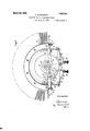
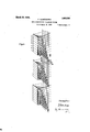
The bancontacts are shapes so that the tabs 68 to 75 lie .11 one and. the some 1' .tl plane or project out from the insulation in which they are embedded in the same radial direction, but bend laterally at different distances from the periphery of their strips oi insulation l-8 so to enable the wires 76-83 that are soldered to the tabs to extend past their edges without contacting with them. Thus with this arrange ment the bare wire 76 soldered to the short tab T5 is enabled to extend past the lateral edges of all the longer soldering tabs 68-7-il and to effect a connection with the corresponding shortest soldering tabs 75, 75 of the other selectors without touching any of the longer soldering tabs. By this .means the contact sets oi": dill'ere selectors are all interconnected by a group oil: bare wires 76-83 that lie one behind the other in a radial plane.
The brushes that wipe over the baul; contacts are arrai d on a nightly different plan in the di erent '1 of selectors (linefinders, group selectcs connectors). The connectors are provided with two sets of three brushes c Z), c and a b The brushes (1, 5 .0 only cooperate t contacts of the top three arcuate rows -whi the brushes (a 5 c coopera e with fourtln fifth and sixth arcua e r l the setting of the sets of brushes o, c and a 7? 0, onto the desired banl'c contact sets two-further two-ended lnrush Z 6 are provided which are arran .d so that when one end of brush leaves the last bani; contact in a row the other end will enter into en; gagcment withthe first contact the same row. The arrangement of the bank contacts of connector is illustrated diagrammati- Ell) llU
the
cally in Fig. 7. in this figure it is seen that '17 of Figures 1 and 2.
tacts only. In Figs. 7 the second set of brushes 622 b c, and the bank contacts wit-h which these brushes cooperate are omitted to avoid complication of the diagram. The two sets of brushes a, b, c and a b 0 are displaced on their shaft in the longitudinal direction of the latter as shown in Fig. 1; the corresponding brushes of the two sets are however electrically interconnected.
The group selectors have two sets of brushes 0, b, 0 and (1,, b 0 which are axially displaced on their shaft in the same way as the brushes of the connectors. The setting of the brushes of a group selector onto the proper groups of bank contacts is effected by a single two-ended brush a, as indicated diagrammatically in Fig. 6. The brush a, wipes alternately over short and long bank contacts while the other brushes wipe over short bank contacts only. The brush 0, and the corresponding brush in the second set of brushes a 12,, 0,, not shown in Fig. 6, each wipe over an arcuate row of 55 contacts, while the brushes (1,, Z), and the corresponding brushes in the second set, not shown in Fig. 6, each wipe over an arcuate row of 50 contacts. The reasons for this arrangement will appear hereinafter in the description of the operations of the circuits.
The line-finders each have two sets of axially displaced brushes similar to the sets of brushes a, b, c and 00,, b 0 except that there is an additional brush (6,, Fig. 5) in each set. All the brushes of the line-finders are single-ended and each brush wipes over 50 bank contacts. The fourth brush, 6,, Fig. 5, of each set of brushes controls the setting of the brush set (1 b 0 onto the bank contact sets of calling lines.
The operations of the circuits of a 1000- line exchange will now be described with reference to Figures 57.'
It will be assumed that the subscriber T desires to establish a connection with a subscriber 772. When the calling subscriber raises his receiver a circuit for the line relay 100 is closed which extends from the negative pole of the battery through the line relay 100, contact 101 of the cut-off relay 103, wire 104, calling subscribers station '1, wire 105, contact 102 of the cut-off relay 103 to the positive pole of the battery. The relay 100 opens its contact 106 and thus renders the calling line engaged. By opening its contact 107 the relay 100 disconnects the negative pole from the designating contacts 109 of the contact banks of all line-finders in the calling subscribers group, and at its contact 108 it closes a circuit for the relay 110 that extends from the negative pole, through 108, 111, relay 110 to the positive pole of the battery. The relay 110 closes at its contact 112, the circuit of the starting magnet 113 that corresponds to the magnet Consequently the brushes 0,, b 0,, e, are caused to travel at a high speed b the brush driving spring. The circuit 0 the starting magnet 113 extends from the positive pole through contact 114 of relay 115, 113, 112, contact 116 of relay 117, brush e through contacts like 107 to the bank contact set of the calling line,
the armature of the magnet 113 falls back and engages with the toothed wheel connected to the brush carrier andthus stops the brushes. The falling back of the armature of the starting magnet 113 is acceler ated by the condenser 118 connected in parallel with the starting magnet winding. The relay 115 is now energized by a current that flows from the negative-pole through 119, 115, 0 cut-off relay 103 to the positive pole of the battery. The relay 115 shortcircuits a part of its winding by its contact 120, and the relay 103 separates the line 'relay 100 from the calling line and at its contacts 121, 122 it extends the calling line through the contacts 123, 124 of relay 115 to the impulse relay 200 of the group selector. The deenergized line relay 100 reconnects the negative pole through its contact 107 to the contact 109, but the magnet 113 is not energized hereby because the contact 114 has been opened by relay 115. The impulse relay 200 is now energized by a current that flows through the calling station T and by closing its contact 201 it energizes the release relay 203 which latter energizes the relay 117 by its contact 204. The latter relay opens its contacts 116, 111 and, by its contacts 131, it extends the finder starting wire 130 to the next idle line-finder and at the same time it closes a locking circuit for itself that extends through the contact 132 and the off-normal contact 133 which was closed when the brushes of the line-finder moved out of their normal positions. The relay 115 is now kept energized by a current that flows from the negative pole through 204, 120, left winding of 115, 0 103-to the positive pole and the potential on the test wire 134 is reduced to such an extent that the busy condition of the calling line is maintained. i
The calling subscriber now sends in a series of seven hundreds impulses. At the current interruption after the first impulse the change-over relay 207 is energized by a current that flows from the negative pole through 205, 208, 207 to the positive pole, and at contact 206 an energizing circuit is closed for the brush setting magnet 213 which is similar to magnet 17 in Figures 1 and 2. This energizing circuit extends from the negative pole through 206, 209, wire 210, the first short bank contact 214-, brush 6,, brush setting magnet 213, that is bridged by the condenser 211, to the positive pole. The magnet 213 attracts its armature and thereby releases the brushes so that the brush a, wipes over a long contact connected to the wire 219 and over contact 220 that is con nected to the negative pole. As long as the brush 6 touches the long contacts the magnet 213 remains energized. It is deenergized however as soon as it reaches the short intermediate contact 215. This shortv contact is connected to battery as soon as the impulse relay 200 reattracts its armature at the end of the first interruption in the series of hundreds impulses aforementioned. The magnet 213 then receives another impulse that flows from the negative pole through 221, contact 222, Wire 223, short intermediate contact 215, brush 0,, 213 to the positive pole. The magnet 213 by attracting its armature releases the brushes again and it remains energized by current flowing through the next long contact connected to the wire 219 until the brush 6, reaches the next short intermediate contact 216. The magnet 213 now lets its armature drop back and arrests the brushes until it is reenergized as a result of the second impulse in the series of hundreds impulses. This energizing current flows from the negative pole through 206, 209, 210, 216, 6 213 to the positive pole. The selector brushes now travel onto the next short intermediate contact 217, where they are again arrested until at the energization of the impulse relay a current impulse flows from the negative pole through 221, 222, 223, 217, 0 213 to the positive pole. The selector brushes are then rotated on to the 11 Kt short intermediatecontact 218 by the brush driving spring. It is thus seen that at each detraction and succeeding reattraction of the armature of the impulse relay the set of selector brushes executes two half or partial steps which amount to a single full step. Seven hundreds impulses cause the brushes to execute seven full or long steps. In er:- ecuting seven long steps a set of brushes completes one half of a revolution and then leaves the rows of arcuate bank contacts with which it cooperates while the other set oi brushes enters into contact with its coordinated bank contacts and executes two long steps thereover so that its brush ultimately stops on the contact 22% that lies between the groups oi bank contact sets g 9,. It is to be noted that the selector controlling brush a, has two ends, one of which reaches the arcuate bank contact row of short and long contacts the moment the other end leaves this contact row.
The set of brushes a 6 0 having been s it onto the group of bans contact sets g, the change-over function now takes place in consequence of a prolonged energization of the impulse relay which causes the deener gization of the change-over relay 207. This relay 207 opens its contacts220, 222, and as the contact 206 or" the impulse relay 200 is now also open the wires 219, 223, 210 that are connected to the row of controlling bank contacts wiped by the brush a, are disconnected from the negative pole of the battery, so that the brush setting magnet does not receive any more brush setting or controlling impulses through the brush 6,. When the contact 226 is closed by the detraction of the armature of the change-over relay 207, the brush setting magnet is energized by a current that flows from the negative pole through the bank contact 225, brush a, relay 227, contact 228 of the energized release relay 203, 226, 213 to the positive pole. This current first causes the slowly detracting relay 227 to attract its armature so as to shortcircuit itself by its own contact 229 and thus cause the energization of the brush setting magnet by a current that flows from the negative pole through 225, 0 230, 231, 229, 228, 226, 213 to the positive pole. The brush setting magnet 213 opens its contacts 232, 233, closes its contact 234:, and before opening contact 230 it also, closes the con tact 235. At the same time the magnet 213 releases the brush carrier so that the brushes are driven by the driving spring at a high speed over the group of bank contact sets 9 until the brush 0 reaches a contact, such as 237, that is not connected to the negative pole. The brush setting magnet 213 is then deenergized so that its armature arrests the brushes. At the same time it extends the calling line through its contacts 232, 233 to the connector (Fig. 7) and opens its contacts 234, 235 while closing contact 230.
V7 hen the relay 227 was energized in the. manner described and by short-circuitmg its own winding immediately thereafter caused the energization of the brush setting magnet 213, the relay 239 was energized by a current that flowed from the negative pole through 238, 234i, 239 to the positive pole of the battery. The relay 239 closed at its contact 240 a locking circuit for itself and at its contact 231 severed the connection be tween contacts 230 and 229 so as to pre vent a renewed short-circuit of the relay when the brush setting magnet 213 was deenergized for the purpose or" arresting the brushes a 6 0 The energization oi the impulse relay 300 of the connector talres place when the call ing subscribers line is extended as described through the brushes of the group selector. The release relay 303 is energized by a, current that flows from the negative pole through 305, 303 to the positive pole. The relay 227 in the group selector is then ener gized by a current that flows from the tive pole through 306, 237, 0 227, 228, 213 to the positive pole. Since, as already exlained, the Contact 231 is now open, the reay 227 does not now short-circuit itself when energized and the comparatively weak current flowing through it does not suflice to energize the brush setting magnet 2l3. The relay 227 at its contacts 242, 243 disconnects the impulse relay 200 from the voice current wires 250, 251 but closes contacts 244, 245 to prevent the deenergization of said impulse relay.
As already explained the connector (Fig. 7) has two sets of three brushes each which are displaced axially and radially with respect toeach other and each of which has only one bank contact wiping end. In addition to the two said sets of one-ended brushes the connector has two two-ended brushes or wipers. In Fig, 7 the two bank contact wiping ends of the brush that wipes over the arcuate row of short and long bank contacts are designated 6 and e, while the ends of the brush that wipes over the controlling bank contact row that contains short bank contacts only are designated d and d. The set of brushes a, b, c is shown in a position in which it has alreadyexecuted five long steps without wiping over any bank contacts and in which it is just commencing to execute its sixth long step. One end of each controlling brush has just wiped'over its row of controlling bank contacts and the other end of each brush (1, e is just starting to wipe over the same bank contact rows.
When the brushes have executed seven complete steps, the brush 6 rests on the short contact 315 at the beginning of the group of bank contact sets 9,. The impulse relay now remains energized for a comparatively long period so that the change-over relay 324, which was kept energized during the dialling impulses through the contacts 304, 326 allows its armature to drop back. As the olf-normal contacts II, I were closed when the brushes of the connector moved out of their initial position, the relay 327 is now energized by a current that flows from the negative pole through contact 328 of the oilnormal switch III, which is still closed, 1,, 329, upper winding of relay 327, contact 330 to the positive pole. The relay 327 at its contact 331 closes a locking circuit for itself that extends through contact 307 to the positive pole, while it disconnectsthe impulse wire 309 from the row of controlling bank contacts that is wiped by the brush 6, and by contact it connects the impulse wire 309 to the contact arm 332 of an auxiliary switch. The auxiliary switch has three contact arms 332, 334, 335 that are rotated step by step by a magnet 336 in such a manner that they execute a forward step at each detraction of the armature of their stepping magnet 336. \Vhen the calling subscriber now sends in two units impulses, the first impulse flows from the negative pole through 307, 308, 333 to the contact arm 332, bank contact 337, bank contact 338 of the connector, control ling brush (Z, brush setting magnet 320 to the positive pole. At the same time a part of the impulse flows through 333, wire 339, contact 340, magnet 3360f the auxiliary switch to the positive pole,so that this magnet tensions its armature spring. The impulse that flows through the bank contact 338 energizes the wiper setting magnct 320 so that this latter releases the connector brushes and the brush driving spring rotates them to the next bank contact 341 that has no connection with the negative pole, so that when it is reached by the controlling brush the brush setting magnet 320 is deenergized. When the impulse relay 300 opens the contact 308 again after the first units impulse, the magnet 336 is deenergized and its detracted armature steps the contact arm 332 forward to the next contact 342that is connected to nector brushes and when the brush cZ reaches the contact 350, is gain deenersized so as to arrest the brushes a, Z), c on the bani: contacts oi the desired line No. 772. The change-over relay 324, which was lrept energized through 30%, 326 while the units dialling impulses were being sent now allows its armature to drop back and by contact 355' connects t re negative pole of the battery to the test relay 356, so that this relay is energized if the wanted line is free by a current that extends from the negative pole through 307, 357, oil-normal. contact 358 355, 356 0, test wire 359, armature relay contact of the wanted subscriber, similar to contact 10-3,
cut-oh" relay, similar to 103, of the wanted subscriber to the positive pole. The test relay closes a ringing current circuit its contacts 360, 361 so that intermittent ringing current now lows from the ringing current generator 363 through the contact arm 3341:, relay 36 i and contacts 365, The intermittent closing of the ringing current circuit is effected by the auxiliary switch whose magnet is connected in the circuit of the interrupter367 when the test relay 356 is energized. The circuit of the operating magnet 336 extends from the negative pole through the interrupter 367, wire 368, relay contact 369, contact 370, magnet to the positive pole. Each time the contact arm 33 i wipes over the arcuate contact 371 the ringing current generator 363 sends ringing current to the wanted subscriber. 'When the latter raises his receiver the current flowing through the relay sea is strengthened so that this relay closes at its Contact 372 an energizing circuit for the relay 373 that extends from the positive pole through 372, left- Winding of 373 to the negative pole. By its contacts 374, 375 the relay new extends the calling line to the wanted line'and its contacts 365, 366 it cuts off the ringing current. Art-contact 330 the relay 373 opens the circuit of relay 327 and this latter-now prepares at its contact 377 a circuit which, when the wanted subscriber replaces his receiver, is established from the negative pole through 378, 377, 380, 379 to the positive pole so that the relay 379 at its contact 381 cuts off the impulse relay 300 andthus initiates the release of the connector. The connector is also released it the calling subscriber replaces his receiver first and thus causes the deenergization of the impulse relay 300. In this case the circuit of the release relay 303 is opened at contact 305 and at contact 382 the brush setting magnet 320 of the connector is connected in a cuit that extends from the negative pole through 332 oil-normal contact I, 320 to the positive pole. The magnet 320 attracts its armature to release the brush carrier and the brushes are now turned into their normal position by the brush driving spring. v fhen they reach their normal position the off-normal l is opened and the brush setting magnet 320 is thus deener'gized.
lVhile the conversational connection was being established the spring winding magnet 333 received current impulses in a circuit extending from the negative pole through 307, 38%, 383 to the positive pole. By this means the off-normal contact 11 that cooperates with the hollow shaft of the selector wasclosed so that when the release relay 303 deenergized current impulses flow from the negative pole through 385, II, 333 to the positive pole. The winding magnet new steps the small toothed wheel of the selector and the hollow shaft round until the spring is fully rewound. As soon as this is ei'l'ected the off-normal contact 11 is opened 1 interrupts the circiiit oi the winding 1st 333.
The restoration of the group selector is initiated by the opening of the circuit of relay contact 306 of the release relay 303 of the connector. By this means the impulse relay 200 oi the group selector is reconnected with the trunk 250, 251 and when the calling subscriber replaces his recciver the circuit of the release relay 203 is opened at contact 201 and at contact 260 of the release relay the brush setting magnet 213 is connected ina circuit that extends from the negative pole through 1 relay con tact 260, 226, 213 to the positive pole. The energized brush'setting magnet 213 new releases the brush carrier and the brush driving spring rotates the brushes forward into th lr normal position in which the off-normal switch is opened to deenergize the magnet 21.3 and thus arrest the brushes. contact 261 the springwinding magnet 263, which in the course of the connection received a current impulse through 264 for the purpose oi closing the off-normal switch H is connected in an impulse circuit that extends from the positive pole through H 261, 263 to the negative pole. The rew'inding magnet 263 now winds the spring and when this winding operation is completed the ottnorinal contact H is opened to interrupt the spring winding impulses through the time ing magneti'he restoration of the linefinder is itiated by the opening of the contact 204 of the release relay 203 of the group selector. By this means the test relay 115 is deenergized and at its contact 166 establishes an impulse circuit through the spring winding magnet 163 that extends from the positive pole through the interrupter 165, winding magnet 163, 166, 167, contact 133 to the negative pole. The winding impulse circuit is interrupted by the off-normal contact 133 when the spring is completely rewound. The brushes are restored to their normal position by the closure of the circuit 'of the brush setting magnet 113 at contact 114. This circuit extends from the positive pole through 114, contact 169, off-normal contact I to the negative pole. As soon as the brushes reach their normal position the winding impulse circuit of magnet 113 is opened at the off-normal contact 1,. All parts of the exchange used for the connection have now been restored to their normal position.
If the wanted subscriber is found busy the test relay 356 is not energized by the current that flows from the negative pole through 307, 357, 358, 355, 356 and brush 0. The calling subscriber then receives a busy tone that is produced by a busy tone current emanating from the coil 390 and passing through contact 391, brush 334, condenser 392, contact 365, contact 393, condenser 394, winding 395 of relay 373 to earth. The tone currents in winding 395 induce alternating currents in the winding of relay 373 and these currents produce a busy signal in the calling subscribers receiver. The calling subscriber then replaces his receiver whereby the impulse relay 300 in the connector and the impulse relay 200 in the group selector are deenergized and the restoring functions, already described, are initiated.
With the type of selector and circuit hereinbefore described a calling subscriber is connected through a group selector in a few hundredths of a second or even faster, while the extension of a connection through the group selector, after its brushes have been set by the dialling impulses, is also effected in about one hundredth of a second.
In the selector shown in Figures 1 and 2 brush setting magnet and a circuit spring winding magnet are employed. In Figures 8 and 9 a modified selector is shown in which both the brush setting and spring winding operations are executed by means of a single magnet. This selector has two ratchet wheels 1, 2 with oppositely directed teeth. The wheel 1 is fixed on a shaft 5 journalled at its bottom end in a frame 9*. The upper bearing of the shaft is not shown. The brushes 6 of the selector, whose ends are adapted to wipe over bank contacts 7, 8*, are mounted on the shaft 5 so as to revolve with the wheel 1 Revolubly mounted on the shaft is the second wheel 2 to which a spring box 10 is fixed. The one end'of the spring in the spring box is connected to the wheel 2 and the other to the shaft 5. When the wheel 1 is held immovable and the wheel 2. is turned the spring in the spring box 10" is wound. Backward rotation of the wheel 2 is prevented by a detent 11.
' The two ratchet wheels 1 and 2 are controlled by the armature 12 of the electromagnet 13. 'The armature 12 is arranged to oscillate about a pivot 14 so that the arresting pawl 15 is swung to and fro in a radial line through the center of the shaft 5, while the end of the arm 16 oscillates in a tangent of the wheel 2*.
Assuming that the spring in the spring box 10 is wound up it will tend to turn the wheel 1 in the direction of the arrow. I This rotation is however prevented by the detent 15 connected to the armature 12. But when the electromagnet 13 is energized the detent 15 is swung away from the teeth of the wheel 1 and at the same time the spring winding pawl 17 is swung forward by the end of the arm 16 to the next tooth in the wheel 2. As the wheel 1 is now released the spring 10 rotates this wheel with the shaft 5 and the brushes 6 at'a high speed until the magnet 13 is deenergized. This decnergization of the electromagnet 13 is caused by the brush 6 reaching a bank contact 8 that is disconnected from the battery, similarly as described in connection with the selector shown in Figures 1 and 2. The detent 15 then moves into the recess between two teeth that is opposite to it at the moment when the brush reaches the disconnected bank contact and the brushes 6 are thus arrested on the corresponding bank contact 8: By this means a connection is established through the brushes 6 and bank contacts 8 with a calling line or trunk.
The selector is returned to its normal position by again energizing the electromagnet 13 The ratchet wheel 1 is now rotated forward by the brush driving spring until a projection 19 on the wheel strikes against a stop 20 In the position in which the wheel 1 is held by the stop 20 a projection (not shown) closes a switch which now sends current impulses through the electromagnet 13. The armature 12 is thus oscillated round its pivot 14 thereby oscillating the spring winding pawl 17 which steps the spring winding wheel 2 in the direction of the arrow. This rotation continues until a cam 21 on the wheel .2 lifts the movable stop 20* and at the same time interrupts the impulses flowing through the electrolnagnet 13. As the wheel is stepped forward by the pull of the spring 22 the detent 15 will drop into a recess between two teeth of the wheel 1 at the moment the spring winding impulses are interrupted so, thatthe rotation of the wheel 1 is prevented at the moment the stop 20 is lifted. When the electromagnet 13 is energized again for new connection the wheel 1 and the brushes are then again whirled round by the spring until the desired line or trunk is reached.
The auxiliary switch with the contact arms 832, 334;, 335 in Fig. 7 can be replaced by a relay which alternately connects the wire 339 to the groups of contacts wiped by the brush (5. Thisrelay is provideo with a winding that is connected to one of these contact groups and to a front contact i m pulse relay 307. it has a second loclnng winding which when the relay is energized is connected to the back contact of the impulse relay. When the impulse relay energized the first winding of the said circuit changing relay is energized in a circuit that extends through the brush setting magnet 320 of the connector. The resistance of the winding of the circuit changing relay is such that the energization of the brush setting magnet is prevented at this time so that the circuit changing relay alone is energized. When the impulse relay now allows its armature to drop back the wire 339 is connected through contact of the circuit changing relay to the brush set-ting magnet and this latter is energized that the brushes oi: the connector execute a short step and thus open the circuit through the energizing winding ot' the circuit changing relay. W hen the impulse relay is new again energized the loclringwinoing of the circuit changing relay is also opened and this relay now connects the wire 389 to the other group of banlr contacts wiped by the brush d. When the impulse relay now drops back again the brush setting magnet is energized and the brushes of the selector execute another step. When the impulse relay 300 is now energized again the circuit changing relay is reenergized and on the ensuing detraction oi the impulse relay 800 the brush setting magnet is again energized. By this means the circuit changing relay alternately connects the wire 839 to the two groups of contacts wiped over by the brush (Z.
I claim 1. In an electro-mechanically controlled telephone system, a switch having brushes and sets of bank contacts, means tor driving said brushes in a continuous motion over a plurality of said contacts, means including a brush setting magnet for setting said brushes onto any desired set of bank con tacts, and a switching device for connecting said brush setting magnet alternatelyto diitfercnt sets of bank contacts.
2. In an electro mechanically controlled telephone system, a switch having brushes and sets of bank contacts, means for driving said brushes in a continuous motion over plurality of said contacts, means including a brush setting magnet for setting said Us telephone system, a plurality of telephone ines, a switch having brushes and sets of bank contacts, means including a brush setting magnet for setting said brushes onto any desired. set of bank contacts, a condenser connected in parallel with said magnet, contacts controll d by said magnet for extending one of said lines through said switch, and a switching device for connecting said brush setting magnet alternately to different sets of bank contacts.
l. in an electro mechanically controlled telephone system, a switch having brushes inc sets of bank contacts, means including a brush setting magnet for setting said brushes onto any desired set oi-banlr contacts, a spring for driving said brushes in a continuous motion over a plurality of said sets of contacts under the control of said magnet, an electric circuit for winding up said spring, and a contact in said circuit closed as long as the switch is in an oft-normal position.
5. in an electro-mechanically controlled telephone system, a. switch having brushes sets or" haul; contacts, means including a brush setting magnet for setting said brushes onto any desired set of ban-l; contacts, a spring for driving said brushes in a continuous motion over a plura ity of said setsoi? of contacts under the control oi said magnet, an electric circuit for winding up said spring, means for sending numerical impulses to said switch from a distant point, and means responsive to the sending of said impulses for closing said circuit.
6. in an electro-mechanically controlled telephone system, switch comprising a rotary brush carrier, plurality of arcuate contacts, sets of brushes CllSu rows of bank placed axially and angularly with respect to each other on said brush carrier, each set of brushes cooperating with a said arcuate row of bank contacts, a spring for rotating said brush carrier, a brush setting magnet for controlling the movements of said brushes, and controlling circuits for the said magnet which extend through bank contacts and a brush or brushes of said switch.
7". In an electro-mechanically controlled telephone system, a numerical switch com prising a rotary brush carrier, a plurality of arcuate rows of bank contacts, sets of brushes displaced axially and angularly with respect to each other on said brush carrier, each set of brushes cooperating with a, said arcuate row of bank contacts, a spring for rotating said brush carrier, a brush setting magnet for controlling the movements of said brushes; and means for controlling long steps of said brushes, said means comprising interconnected bank contacts, one of which is situated at the beginning of each group of bank contact sets and other interconnected bank contacts one of which is situated at or near the. middle of each group of bank contact sets, a numerical impulse receiving relay, and means for connecting an armature contact of said relay alternately to said sets of interconnected bank contacts.
8. In an electro-mechanically controlled telephone system, a numerical switch comprising a rotary brush carrier, a plurality of arcuate rows of bank contacts, sets of brushes displaced axially and angularly with respect to each other on said brush carrier, each set of brushes cooperating with a said arcuate row of bank contacts, a spring for rotating said brush carrier, a brush setting magnet for controlling the movements of said brushes, means for controlling long steps of said brushes, said means comprising interconnected bank contacts one of which is situated at the beginning of each group of bank contact sets and other interconnected bank contacts one of which issituated at or near the middle of each group of bank contact sets, a numerical impulse receiving relay, means for connecting an armature contact of said relay alternately-to the said sets of interconnected bank contacts, and long bank contacts located between said bank contacts at the middle and beginning or end of each group of bank contact sets.
9. In an e'lectro-mechanically controlled telephone system, a numerical switch comprising a rotary brush carrier, a'plurality of arcuate rows of bank contacts, sets of brushes displaced axially and angularly with respect to each other on said brush carrier, each set of brushes cooperating with a said arcuate row of bank contacts, a spring for rotating said brush carrier, a brush setting magnet for contolling the movements of said brushes; and means for controlling long steps of said brushes; said means comprising interconnected bank contacts one of which is situated at the beginning of each group of bank contact sets and other interconnected bank cont-acts one of which is situated at or near the middle of each group of bank contact sets, a numerical impulse receiving relay, and further means for controlling short steps of said brushes, said further means comprising two sets of interconnected bank contacts each of which is associated with the set of bank contacts belonging to a certain line, and means for connecting an armature contact of said relay alternately first to the sets of interconnected bank contacts for controlling long steps of the brushes and then to the sets of interconnected bank contacts for controlling short steps of said brushes.
10. In an electro-mechanically controlled telephone system, arcuate rows of bank contacts, a rotary brush carrier, single-ended brushes angularly and axially displaced on said brush carrier and adapted to cooperate alternately with different arcuate rows of bank contacts, a brush with a plurality of ends each of which cooperates with the same arcuate row of bank contacts, a spring for rotatingsaid brushes, a brush setting magnet for controlling the movements of Said brushes, and energizing circuits for said magnet which extend through said mu tiended brush and the bank contacts with which it cooperates.
11. In an electro-mechanically controlled telephone system, arcuate rows of bank contacts, a rotary brush carrier, single-ended brushes angularly and axially displaced on said brush carrier and adapted to cooperate alternately with different arcuate rows of bank contacts, a brush with a plurality of ends each of which cooperates with the same arcuate row of'bank contacts, a spring for rotating said brushes, a brush-setting magnet for controllinglong step group selecting movements of said brushes, and energizing circuits for said magnet.
12. In an electro-mechanically controlled telephone system, arcuate rows of bank contacts, a rotary brush carrier, single-ended brushes angularly and axially displaced on said brush carrier and adapted to cooperate alternately with different arcuate rows of bank contacts, multi-ended brushes each of which cooperates with an arcuate row of bank contacts, a spring for rotating said brushes, a brush-setting magnet for controlling long-step and short-step movements of said brushes, and energizing circuits for,
said magnet which extend through said multi-ended brushes and the bank contacts with which they cooperate.
13. In an electro-mechanically controlled telephone system, a selector with two coaxial shafts interconnected by a shaft driving spring, brushes carried in a continuous motion over a plurality of bank cont-act sets by the spring driven shaft, a toothed wheel fixed onthe brush carrying shaft, bank contacts wiped by said brushes, and an electromagnet with an armature that stops said toothed wheel and brushes when the latter reach a bank contact connected to an electrical brush stopping potential.
14. In an electro-mechanically controlled telephone system, a selector with two coaxial shafts interconnected by a shaft driving sprin brushes carried by the spring-driven shaft, a toothed brush stopping wheel fixed. on the brush carrying shaft, a toothed spring winding wheel which is of smaller diameter than v the brush-stopping wheel and,
, spring, brushes carried in a continuous motion over a plurality of bank contact sets by the spring driven shaft, a unidirectionally rotated toothed wheel fixed on the brush carrying shaft, bank contacts wiped by said brushes, and an electromagnct with an armature that stops said toothed wheel and brushes when the latter reach a ban k contact connected to an electrical brush stopping potential; 7 it). In an electro-mechanically controlled telephone system, a selector with two coaxial shafts interconnected. by a shaft driving spring, brushes carried by the spring driven shaft, a toothed wheel fixed on the brush carrying shaft, bank contacts wiped by said brushes, an electrom'agi'iet with an armature that stops said toothed wheel and brushes when the latter reach a bank contact connected to an electrical brush stopping potential, an arresting member attached to the brush carrying shaft, and a movable stop that engages with said arresting member and stops the brush carrying shaft when the brushes reach their normal position.
17. In an electromechanically controlled telephone system, a switch comprising a row of bank contacts, a brush, a power device for moving said brush in a continuous motion over a plurality of said contacts, a brush setting magnet for stopping the brush at desired contacts, an electrical connection which interconnects a group of said contacts, a second electrical connection which interconnects a second group of said contacts, a contact of the second group following after e 'ch contact of the first group in the row, energizing circuits for said magnet, and a switching device for closing said energizing circuits through said brush setting magnet, said brush, and through said first and second electrical connections alternately.
18. In an electromechanically controlled telephone system, a main switch comprising a row of bank contacts, a brush, a power device for moving said brush over said con tacts, a brush setting magnet for stopping the brush at desired contacts, an electrical connection which interconnects a group of said contacts, a second electrical connection which interconnects a second group of said contacts, a contact of the second group following after each contactof the first group in the row, an auxiliary switch comprising a row of fixed contacts, a brush, a magnet for moving said brush step-by-step over said. fixed contacts, one group of said fixed contacts being connected to the first said electrical connection and a second group of said fixed contacts'being connected to the second said electrical connection, a contact of the second group of fixed contacts fol lowing after each contact of the first group of fixed contacts, and alternately operative energizing circuits for said brush setting magnet including said brushes, bank contacts and fixed contacts.
19. In an electromechanically controlled telephone system, a switch comprising a row of controlling bank contacts, a controlling brush that wipes over the controlling bank contacts, rows of talking current bank contacts, talking current brushes that wipe'o'ver the talking current bank contacts, a power device for moving said. brushes in a continuous motion over a plurality of bank contacts, a brush setting magnet for stopping the brushes at desired sets of bank contacts, an electrical connection which interconnects a group of said controlling bank contacts, a second electrical connection which interconnects a second group of said controlling bank contacts, a contact of the second group following after each, contact of the first group, ener izing circuits for said magnet, and a switching device for closing said energizing circuits through said brush setting magnet, said controlling brush, and through said first and second electrical connections alternately.
20. In an electromechanically controlled telephone system, a switch comprising a row of bank contacts, a brush, a power device for moving said brush over said contacts, a brush setting magnet for stopping the brush at desired contacts, a condenser for quickening the operation of said magnet, an electrical connection which interconnects a group of said contacts, a second electrical connection which interconnects asecond group of said contacts, a contact of the second group following after each contact to the first group in the row, energizing circuits for said magnet, and a switching device for closing said energizing circuits through said brush set-ting magnet, said brush, and through said first and second electrical connections alternately.
21. In an electromechanically controlled telephone system, a switch comprising a row of bank contacts, a brush, a spring for moving said brush in a continuous motion over a plurality of said contacts, a brush setting magnet for stopping the brush at desired contacts, an electrical connection which interconnects a group of said contacts, a second electrical connection which interconnects a second group of said contacts, a con tact of the second group following after each contact of the first group in the row, energizing circuits for said magnet, and a switching device for closing said, energizing circuits through said brush setting magnet, said brush, and through said first and second electrical connections alternately.
22. In an electromechanically controlled telephone system, a switch comprising a row of bank contacts, a brush, a spring for moving said brush in a continuous motion over a plurality of said cont-acts, a brush setting magnet for stopping the brush at desired contacts, an electrical connection which interconnects a group of said contacts, a second electrical connection which intercon nects a second group of said contacts, a con tact of the second group following after each contact of the first group in the row, energizing circuits for said magnet, a switching device for closing said energizing circuits through said brush setting magnet, said brush, and through said first and second electrical connections alternately, and clectrically controlled means for rewinding said spring after it has operated said brush.
23. In an electromechanically controlled telephone system, a switch comprising a row of primary controlling bank contacts, a row of secondary controlling bank contacts, a primary controlling brush that cooperates with the primary controlling bank contacts, a secondary controlling brush that cooperates with the secondary controlling bank contacts, a power device for moving said brushes, a brush setting magnet for stopping the brushes first at a desired group of bank contacts and then at a desired contact in a group, an electrical connection which interconnects a group of said primary controlling bank contacts, a second electrical connection which interconnects a second group of said primary controlling bank contacts, a contact of the second group of primary contacts following after each contact of the first group, energizing circuits for said magnet, a device for closing said energizing circuits through said brush setting magnet, said primary controlling brush, and through said first and second electrical connections alternately, and means for subsequently energizing said magnet through said secondary controlling brush and secondary controlling bank contacts.
24. In an electromechanically controlled telephone system, a switch comprising bank contacts, brushes adapted to glide in a continuous motion over a plurality of said bank contacts, a continually acting power device tending to move said brushes, one detent both for holding the brushes in an initial position against the action of said power and for positively stopping the powerdriven brushes on any desired bank contact, and an electromagnet for operating said detent.
25. In an electromechanically controlled telephone system, a switch comprising bank contacts, brushes adapted to glide in a continuous motion over a plurality of said bank contacts, a continually acting power device tending to move brushes, one dctont for holding the brushes in an initial position a ainst the action of said power device and for firstpositively stopping the power-driven brushes at a. plurality of points arranged at certain distances apart and for then positively stopping the brushes after they have travelled a shorter distance than the distance between two said points, and an electromagnet for operating said detent.
26. In an electromechanically controlled telephone system, a switch comprising bank contacts, brushes adapted to glide in a continuous motion over a plurality of said bank contacts, a continually acting power device tending to move brushes, one detent for holding the brushes in an initial position against the action of said power device and for first positively stopping the powerdriven brushes at a plurality of points arranged at certain distances apart and for then positively stopping the brushes at a plurality of other points placed closer together than the said first points, and an electromagnet for operating said detent.
27. In an electromechanically controlled telephone system, a switch comprising bank contacts, rotary brushes adapted to glide in a continuous motion over a plurality of said bank contacts, a continually acting power device tending to move said brushes, one detent for holding the brushes in an initial position against the action of said power device for positively stopping the powerdriven brushes on any desired bank contact and for finally stopping the brushes again in their initial position, and an electromagnet for operating said detent.
28. In an electromechanically controlled telephone system, a switch comprising bank contacts, rotary brushes adapted to glide in a continuous motion over a plurality of said bank contacts, a continually acting power device tending to move said brushes, one detent both for holding the brushes in an initial position against the action of said power and for positively stopping the power-driven brushes on any desired bank contact and for subsequently stopping the brushes again in their initial position, and an electromagnet for operating said detent.
29. In an electron'iechanically controlled telc 'ihone system, a switch comprising bank contacts, rotary brushes adapted to glide in a continuous motion over a plurality of said bank contacts, a continually actingpower device tending to move said brushes, one dotent for holding the brushes in an initial position against the action of said. power device and for first positively stopping the power-driven brushes at a plurality of points arranged a certain distance apart and for then positively stopping the brushes at a plurality of other points placed closer "together and for subsequently stopping the brushes again in their initial position, and an electromagnettor operating said detent.
30. In an electromechanically controlled telephone system, a switch comprising bank contacts, brushes adapted to glide over said bank contacts, a brush carrier, toothed member fixed to said brush carrier, a continuously acting power device tending to move said brushes, one detent that cooperates With said toothed member both for holding the brushes in an initial position against the action of said power and for positively stopping: the power driven brushes on any desired bank contact, and an electron'iagnet for holding said detent away from said toothed member while the brushes are moving.
31. In an clectroincchanically controlled telephone system, a switch comprising bank contacts, brushes adapted to glide over said bank contacts, a brush carrier, a toothed member 'lixed to said brush carrier, a co11- tinuously acting power device tending to move said brushes, one detent that cooperates with said toothed member both for nolding the brushes in an initial position against the action of said power and for positively stopping the power driven brushes on any desired bank contact, an electron'iagnetfor holding said detent away from said toothed member while the brushes are moving, and aco'ndenser for quickening the detaining action of said detent.
In testimony whereof I have aliixed my signature.
FRITZ ALDENDORFF.
Applications Claiming Priority (1)
| Application Number | Priority Date | Filing Date | Title |
|---|---|---|---|
| DE1663230X | 1924-04-03 |
Publications (1)
| Publication Number | Publication Date |
|---|---|
| US1663230A true US1663230A (en) | 1928-03-20 |
Family
ID=7738624
Family Applications (1)
| Application Number | Title | Priority Date | Filing Date |
|---|---|---|---|
| US19556A Expired - Lifetime US1663230A (en) | 1924-04-03 | 1925-03-30 | Electromechanical telephone system |
Country Status (3)
| Country | Link |
|---|---|
| US (1) | US1663230A (en) |
| DE (1) | DE466272C (en) |
| FR (1) | FR600519A (en) |
Cited By (1)
| Publication number | Priority date | Publication date | Assignee | Title |
|---|---|---|---|---|
| US2778879A (en) * | 1950-07-27 | 1957-01-22 | Hartford Nat Bank & Trust Co | Control device for use in automatic signalling system |
-
1924
- 1924-04-04 DE DEA41957D patent/DE466272C/en not_active Expired
-
1925
- 1925-01-13 FR FR600519D patent/FR600519A/en not_active Expired
- 1925-03-30 US US19556A patent/US1663230A/en not_active Expired - Lifetime
Cited By (1)
| Publication number | Priority date | Publication date | Assignee | Title |
|---|---|---|---|---|
| US2778879A (en) * | 1950-07-27 | 1957-01-22 | Hartford Nat Bank & Trust Co | Control device for use in automatic signalling system |
Also Published As
| Publication number | Publication date |
|---|---|
| DE466272C (en) | 1928-10-05 |
| FR600519A (en) | 1926-02-09 |
Similar Documents
| Publication | Publication Date | Title |
|---|---|---|
| US1663230A (en) | Electromechanical telephone system | |
| US1725044A (en) | aldendorff | |
| US1699514A (en) | Electrical switch | |
| US1712243A (en) | Automatic electric switching system | |
| US1252028A (en) | Telephone-exchange system. | |
| US1718449A (en) | Automatic telephone system | |
| US1334105A (en) | lundell | |
| US2576220A (en) | Automatic switch control circuit | |
| US2923774A (en) | Autoamtic telephone system | |
| US1849986A (en) | Automatic telephone switch | |
| US1800810A (en) | Single-impulse variable-selecting device | |
| US1387180A (en) | Telephone system | |
| US1110613A (en) | Automatic telephone system. | |
| US1705462A (en) | Automatic telephone system | |
| US2143589A (en) | Telephone system | |
| US1841679A (en) | Telephone system | |
| US1567280A (en) | Telephone-exchange system | |
| US1730049A (en) | Electromechanically-controlled switch and remote-control signaling and telephone system | |
| US1252462A (en) | Automatic switching mechanism. | |
| US1668541A (en) | Traffic recorder for telephone systems | |
| US1289704A (en) | Telephone system. | |
| US1296680A (en) | Telephone-exchange. | |
| US1146583A (en) | Automatic telephone-exchange system. | |
| US2345386A (en) | Switching device | |
| US2211754A (en) | Apparatus for recording telephone call charges |