US1663227A - Locomotive equalizing mechanism - Google Patents
Locomotive equalizing mechanism Download PDFInfo
- Publication number
- US1663227A US1663227A US78833A US7883326A US1663227A US 1663227 A US1663227 A US 1663227A US 78833 A US78833 A US 78833A US 7883326 A US7883326 A US 7883326A US 1663227 A US1663227 A US 1663227A
- Authority
- US
- United States
- Prior art keywords
- equalizing
- frame
- locomotive
- equalizer
- main frame
- Prior art date
- Legal status (The legal status is an assumption and is not a legal conclusion. Google has not performed a legal analysis and makes no representation as to the accuracy of the status listed.)
- Expired - Lifetime
Links
- 230000003137 locomotive effect Effects 0.000 title description 27
- 230000007246 mechanism Effects 0.000 title description 6
- 230000000153 supplemental effect Effects 0.000 description 21
- 238000010276 construction Methods 0.000 description 4
- 238000006073 displacement reaction Methods 0.000 description 2
- RYGMFSIKBFXOCR-UHFFFAOYSA-N Copper Chemical compound [Cu] RYGMFSIKBFXOCR-UHFFFAOYSA-N 0.000 description 1
- 238000005266 casting Methods 0.000 description 1
- 238000006243 chemical reaction Methods 0.000 description 1
- 238000007689 inspection Methods 0.000 description 1
- NJPPVKZQTLUDBO-UHFFFAOYSA-N novaluron Chemical compound C1=C(Cl)C(OC(F)(F)C(OC(F)(F)F)F)=CC=C1NC(=O)NC(=O)C1=C(F)C=CC=C1F NJPPVKZQTLUDBO-UHFFFAOYSA-N 0.000 description 1
Images

Classifications
-
- B—PERFORMING OPERATIONS; TRANSPORTING
- B61—RAILWAYS
- B61F—RAIL VEHICLE SUSPENSIONS, e.g. UNDERFRAMES, BOGIES OR ARRANGEMENTS OF WHEEL AXLES; RAIL VEHICLES FOR USE ON TRACKS OF DIFFERENT WIDTH; PREVENTING DERAILING OF RAIL VEHICLES; WHEEL GUARDS, OBSTRUCTION REMOVERS OR THE LIKE FOR RAIL VEHICLES
- B61F5/00—Constructional details of bogies; Connections between bogies and vehicle underframes; Arrangements or devices for adjusting or allowing self-adjustment of wheel axles or bogies when rounding curves
- B61F5/26—Mounting or securing axle-boxes in vehicle or bogie underframes
- B61F5/30—Axle-boxes mounted for movement under spring control in vehicle or bogie underframes
- B61F5/36—Arrangements for equalising or adjusting the load on wheels or springs, e.g. yokes
Definitions
- This invention relates to locomotive equalizing mechanisms and is particularly useful in connection with locomotives having a main frame and a supplemental or truck frame equipped with multiple sets of wheels journalled therein.
- Another object of my invention the provision of an equalizing connection between the equalizing system of a locomotive main frame and the equalizing system of a locomotive supplemental frame mounted to transmit the reacting thrusts of the on nected equalizing systems to the main frame.
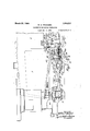
- I v Fig. 1 is a fragmentary side, elevation of the rear portion of a locomotive illustrating the application of my improvements thereto;
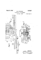
- Fig. 2 is a fragmentary one-half plan view of Fig. 1' with the fire box and boiler removed;
- Fig. 3 is a. section taken substantially on line 33 of Fig. 1 looking toward the right;
- Fig. 5 is a section taken on the line 5-5 of Fig. 4.
- Fig. 6 is an end view of Fig. l.
- Fig, 1 it will be seen that I have shown a portion of the boiler 6 and the are box 7v of a iactmtnttpbbiii supplemental frame B is articulated atlfits'.
- the mainframe, A is shown of. Standard construction comprisingtwo side members 9, connected together by m ans of cross members, the rear cross member being' des ignated by the numeral 10.
- the drivers 11 are journalled in pedestal's'in the main frame by means ofthe boxes p
- the articulatedsupplemental frame B' is provided with pedestalsin the idemember's 13 for the journal boxes14 of the pair of axles 15.
- the side memb'ers ,l3 are connected by cross members, the forward'cross member 16 beingprovided' with atongue 17 which is apertured so as to receive the a'i tic: ulationpin8. u 7 u
- the cross member of themain frame. is provided with a pocket 18 for receiving the tongue 17..
- the upper and lower walls of the pocket 18 are apertured toreceive'the pin 8 and the lower wall is provided with a. boss 19over which the forward eye of the safety bar 20 is fitted.
- safety bar receives the safety bar pin 21', which pin islheld in place inthe cross member 16 of the supplemental frame by means of the keeper 22.
- Thetwo eyes of the safety bar 20 have a loosefit over the boss 19fai1d' pin 21 respectively soflthat the safety bar only functions upon failure of the driving connection at 8 H
- the main frame'A is" connected .to' the boiler in the usual manner by means of ex; pansion bearers, the rearone 23 of which is shown between the boiler and the cross member 10.
- the imposed weight is transmitted through the main frame spring equalizing system C.
- Fig. 1 it will be seen that I interpose a pair of bearer supports 26, one at either side, between the fire box and the supplemental frame.
- the imposed weight of the fire box is transmitted through the supplemental frame equalizing system D.
- equalizing systems C and D are connected together as by the equalizing 'means indicated as a whole by'the reference letter E now to be described in detail.
- the equalizing means E comprises a movable carrier or fulcrum member 27 ,the con struction of which will be clear on inspection of Figs. 4:, 5 and '6, in which member the equalizer levers 28 are fulcrumed at 28.
- the equalizer levers 28 are connected at their free ends tothe equalizing systems G and D of the main frame and supplemental frame respectively, the 7 connection being made through the medium of the cross equalizers29 and 30 and the hangers or links 31 and 32 of the equalizingsystems C and D respectively.
- the carrier or fulcrum member 27 is mounted for rotation in a horizontal plane about the axis of articulation of the supplementalframe to which end the said member is aperturedat 33 to fit overthe articulation pin; 8 before mentioned, in addition to which the member is provided with a recess 34 concentric with the aperture 33 for interengagement with the boss 35 on the underside of the cross member 10 of the main frame,
- clips 39 (see Figs. 2 and 3) on the castings or outboard bearings 40, which clips serve to hold the member 27 in place before spring connection is made.
- the clips also serve to catch the fulcrum member 27 and .to keep it from falling away from the cross member 10 in the event of'failure of the connections.
- the fulcrum member also carries a safety device 41 which prevents themain pivot pin 8 from dropping out in case of a broken pin.
- I can arrange for one point offulcrum for each of the equalizer levers 28, or for a series of points of fulcrum by providing a series of spaced holes in the fulcrum member 27 and in the lever so that a varied distribution can be secured by changing the fulcrum pin from one set of holes to another.
- I claim 1 The combination with a main locomotive frame equalizing system and an articulated supplemental frame equalizing system, of equalizing means connectingsaid systems and including a movable carrier for said equalizing means operating to maintain said means in a predetermined relation to the supplemental frame equalizing system as the supplemental frame articulates, said carrier being mounted to transmitreact-ing thrusts of the equalizing systems to the main frame.
- equalizing means connecting said systems including equalizer levers having their free ends connected to the equalizing systems and a carrier for said levers rotatable about the axis of articulation and attached to one means in a predetermined relation to the supplemental frame equalizing system as the supplemental frame articulates, said carrier being held in operative position by the equalizer connections.
- equalizing means connecting said systems and including a movable carrier for said equalizing means operating to maintain said means in a predetermined relation to the supplemental frame equalizing system as the supplemental frame articulates, said carrier being held in operative position by the equalizer connections, and additional means inclependent of the equalizers adapted to support said carrier.
- equalizing means connecting said systems including equalizer levers having their free ends connected to the aforesaid cross equalizers, and a carrier for said levers movable about the axis of articulation of the frames.
- equalizing means connecting said systems and including a fulcrum member rotatable about the axis of articulation of the trucks under the influence of articulation of the trucks.
- equalizing means connecting said systems and including a fulcrum member rotatable about the axis of articulation of the trucks under the influence of articulation of the trucks, and means preventing unintended displacement of said fulcrum member.
- a connecting unit for equalizing systems of articulated trucks including equalizing levers connected at their opposite ends to said systems, a fulcrum for said levers rotatable about the articulation pin, and means carried by said fulcrumfor preventing unintended displacement of said pin.
- a main frame having the usual side members and a cross member connecting the rear ends of the side members; a truck frame articulated to said crossmember; an equalizing system for the main frame; an equalizing system for the truck frame; and equalizing means connecting said systems including equalizing levers, a fulcrum member for saidlevers rotatable about the axis of articulation of the main and truck frames, and interengaging. means between said fulcrum member and the aforesaid cross member.
- main frame having the usual side members and a cross member connecting the rear ends of the side ⁇ members; a truck frame articulated to said cross member; an equalizing system for the main frame; an equalizing system for the truck frame; and equalizing means connecting said systems including equalizing levers, a fulcrum member for said levers rotatable about the axis of articulation of the main and truck frames; a finished bearing surface on the under surface of the main rame cross member; and a. finished bearing surface on the upper surface of the fulcrum member arranged to abut when the various parts are operatively connected whereby to provide a seat on which the fulcrum member rotates.
- equalizer means for the main frame equalizer means for the truck frame
- equalizer means for the truck frame and equalizing means connecting said main and truck frame equalizer means including means for maintaining said connecting equalizing means in a fixed relation to the truck frame equalizer means.
- equalizer means for the main frame equalizer means for the truck frame, connecting equalizer means between the two, and a movable carrier on which said means is 'mounted, said carrier being pivoted around the axis of the truck frame and main frame pivot.
- equalizer means for the main frame equalizer means for the truck frame, connecting equalizer means between the two, and a movable carrier on which said means is mounted, said carrier being mounted on the main frame.
- equalizer means for the main frame equalizer means for the truck frame
- connecting equalizer means between the two and a carrier on which said means is mounted, said carrier being pivotally carried by the main frame and adapted to maintain s'aid connecting equalizer means in a fixed relation to the truck frame equalizer means.
- a movable carrier for locomotive spring equalizing means comprising a memher having spaced equalizer mountings, pivot her having spaced equalizer mountings, pivot means intermediate such mountings, an opermeans intermediate such mountings, and an ating extension by which the carrier is 10 operating extension by Which the carrier is moved, and locomotive weight bearer means.
- a movable carrier for locomotive signed my name. spring equalizing means, comprising a mem- WILLIAM E. VVOODARD.
Landscapes
- Engineering & Computer Science (AREA)
- Mechanical Engineering (AREA)
- Aiming, Guidance, Guns With A Light Source, Armor, Camouflage, And Targets (AREA)
Description
March 20, 19 28. w. E. WOODARD LOCOMOTIVE EQUALIZING MECHANISM Filed Jan. 2. 1926 3 Sheets-Sheet 1 INVENTOR ll (Pl/f 1M. ATTORNEY5 March 20, 1928.
' w. E. wooDARD LOCOMOTIVE EQUALIZING MECHANISM Filed Jan. 2. 1926 3 Sheets-Sheet 2 INVENTOR NM, 6 MM f-Mw ATTORNEYG L A EL; 1
Maich 20, 1928.
I 1,663,227 W. E. WOODARD LOCOMOTIVE EQUALIZING MECHANISM Filed Jan. 2. 1926 3 Sheets-Sheet 3 IN VEN TOR 6. W 41 BY VMW A TTORNEYS Patented Mar. 20, 1928.
WILLIAM E. woonann, or roniis'r HILLS, NEW YORK.
noooivro'rrvn EQUALIZING momma.
Application filed .T anu'ary 2, 1926. Serial no. 723L833...
This invention relates to locomotive equalizing mechanisms and is particularly useful in connection with locomotives having a main frame and a supplemental or truck frame equipped with multiple sets of wheels journalled therein. i
It has been found that for the proper Operation of the entire locomotive it is important to have the equalizing systems of the articulated frames connected together, and it is to a simple construction efi'ectively accomplishing such end that this invention is directed. U
It is, therefore, one of the primary objects of my invention to provide an improved equalizing mechanism for articulated frames of simple construction in which the equalizing system of one frame is efiecti'vely con nected to the equalizing system of the other frame in all positions'of articulation.
Another object of my invention the provision of an equalizing connection between the equalizing system of a locomotive main frame and the equalizing system of a locomotive supplemental frame mounted to transmit the reacting thrusts of the on nected equalizing systems to the main frame.
How the foregoing, togetherwith such other objects and advantages as may hereinafter appear, or are in'cidentto my invention are realized, is illustrated in preferred form in the accompanying drawings, wherein I v Fig. 1 is a fragmentary side, elevation of the rear portion of a locomotive illustrating the application of my improvements thereto; I
Fig. 2 is a fragmentary one-half plan view of Fig. 1' with the fire box and boiler removed;
Fig. 3 is a. section taken substantially on line 33 of Fig. 1 looking toward the right;
at is a plan view of the carrier or fulcrum member which I employ;
Fig. 5 is a section taken on the line 5-5 of Fig. 4. V
Fig. 6 is an end view of Fig. l.
Referring now to Fig, 1 it will be seen that I have shown a portion of the boiler 6 and the are box 7v of a iactmtnttpbbiii supplemental frame B is articulated atlfits'.
forward end to the rear endof the main frame A, as'by means of the pivotal or hinge pin connection 8 which permits the supplemental frame to swing laterally 'with respect to the main frame curving. The mainframe, A is shown of. Standard construction comprisingtwo side members 9, connected together by m ans of cross members, the rear cross member being' des ignated by the numeral 10. The drivers 11 are journalled in pedestal's'in the main frame by means ofthe boxes p The articulatedsupplemental frame B' is provided with pedestalsin the idemember's 13 for the journal boxes14 of the pair of axles 15. The side memb'ers ,l3 are connected by cross members, the forward'cross member 16 beingprovided' with atongue 17 which is apertured so as to receive the a'i tic: ulationpin8. u 7 u The cross member of themain frame. is provided with a pocket 18 for receiving the tongue 17.. The upper and lower walls of the pocket 18 are apertured toreceive'the pin 8 and the lower wall is provided with a. boss 19over which the forward eye of the safety bar 20 is fitted. The rear eye of the,
safety bar receives the safety bar pin 21', which pin islheld in place inthe cross member 16 of the supplemental frame by means of the keeper 22. Thetwo eyes of the safety bar 20 have a loosefit over the boss 19fai1d' pin 21 respectively soflthat the safety bar only functions upon failure of the driving connection at 8 H The main frame'A is" connected .to' the boiler in the usual manner by means of ex; pansion bearers, the rearone 23 of which is shown between the boiler and the cross member 10. The imposed weight is transmitted through the main frame spring equalizing system C.
Referring to Fig. 1 it will be seen that I interpose a pair of bearer supports 26, one at either side, between the fire box and the supplemental frame. The imposed weight of the fire box is transmitted through the supplemental frame equalizing system D.
The equalizing systems C and D are connected together as by the equalizing 'means indicated as a whole by'the reference letter E now to be described in detail.
The equalizing means E comprises a movable carrier or fulcrum member 27 ,the con struction of which will be clear on inspection of Figs. 4:, 5 and '6, in which member the equalizer levers 28 are fulcrumed at 28. The equalizer levers 28 are connected at their free ends tothe equalizing systems G and D of the main frame and supplemental frame respectively, the 7 connection being made through the medium of the cross equalizers29 and 30 and the hangers or links 31 and 32 of the equalizingsystems C and D respectively. i
The carrier or fulcrum member 27 is mounted for rotation in a horizontal plane about the axis of articulation of the supplementalframe to which end the said member is aperturedat 33 to fit overthe articulation pin; 8 before mentioned, in addition to which the member is provided with a recess 34 concentric with the aperture 33 for interengagement with the boss 35 on the underside of the cross member 10 of the main frame,
' thus providing additional rotative' support.
The rotative movement above referred to is imparted to the fulcrum member through the medium of an extension thereon engaging some convenient point on the trailer truck, in this instance being shown as a rearwardly extending arm 36 apertured to loosely fit over the safety bar pin 21 which is extended for this purpose. Thus it will be seen that as the supplemental frame or truck articulates in curving the fulcrum member moves therewith, thus maintaining the equalizers 28 in a predetermined relation with the supplemental frame equalizing system D,'it being evident that the springs and equalizers on the supplemental frame follow the movements of the frame itself in whatever position it may assume under the izer system C.
Referring now more particularly to Fig.
1 it will be seen that as the reaction of the hangers 31 and 32 connected to the equalizers is an upward thrust, the fulcrum member 27 will always be in contact with the cross member 10 of the main frame, the bottom of which is provided with machinedsurfaces 37 coacting with the machined surfaces 38 on the member 27 to form a seat on which the fulcrum member rotates. This arrangement is very advantageous in that the heavy upward thrust above mentioned is resisted by the main frame structure, which structure at this point is strongly connected to the boiler by the expansion bearer 23, and the expansion plate 24 which forms a connection between the mud ring 25 and the outboard bearings 40. These bearings 40 are attached to the main frame as indicated in Fig. 3. r
For purposes of assembling before the spring hangers are all connected, I arrange clips 39 (see Figs. 2 and 3) on the castings or outboard bearings 40, which clips serve to hold the member 27 in place before spring connection is made. The clips also serve to catch the fulcrum member 27 and .to keep it from falling away from the cross member 10 in the event of'failure of the connections.
The fulcrum member also carries a safety device 41 which prevents themain pivot pin 8 from dropping out in case of a broken pin.
It is understood that I can arrange for one point offulcrum for each of the equalizer levers 28, or for a series of points of fulcrum by providing a series of spaced holes in the fulcrum member 27 and in the lever so that a varied distribution can be secured by changing the fulcrum pin from one set of holes to another.
I claim 1. The combination with a main locomotive frame equalizing system and an articulated supplemental frame equalizing system, of equalizing means connectingsaid systems and including a movable carrier for said equalizing means operating to maintain said means in a predetermined relation to the supplemental frame equalizing system as the supplemental frame articulates, said carrier being mounted to transmitreact-ing thrusts of the equalizing systems to the main frame.
2. The combination with a main locomotive frame equalizing system and an articulated supplemental frame equalizing system, of means connecting said systems including 'equalizerlevers having their, free ends connected to the equalizing systems and a carrier' for said levers rotatable about the axis of articulation and connected to the supplemental frame for movement therewith.
3. In a locomotive having two equalizing systems for articulated frames, the combination of equalizing means connecting said systems including equalizer levers having their free ends connected to the equalizing systems and a carrier for said levers rotatable about the axis of articulation and attached to one means in a predetermined relation to the supplemental frame equalizing system as the supplemental frame articulates, said carrier being held in operative position by the equalizer connections.
5. The combination with a main locomotive frame equalizing system and an articulated supplemental frame equalizing system, of equalizing means connecting said systems and including a movable carrier for said equalizing means operating to maintain said means in a predetermined relation to the supplemental frame equalizing system as the supplemental frame articulates, said carrier being held in operative position by the equalizer connections, and additional means inclependent of the equalizers adapted to support said carrier.
6. In a locomotive having two equalizing systems for articulated frames each including cross equalizer, the combination of equalizing means connecting said systems including equalizer levers having their free ends connected to the aforesaid cross equalizers, and a carrier for said levers movable about the axis of articulation of the frames.
7. In a locomotive having articulated multiple axle trucks each provided with an equalizing system, the combination of equalizing means connecting said systems and including a fulcrum member rotatable about the axis of articulation of the trucks under the influence of articulation of the trucks.
8. In a locomotive having articulated multiple axle trucks each provided with an equalizing system, the combination of equalizing means connecting said systems and including a fulcrum member rotatable about the axis of articulation of the trucks under the influence of articulation of the trucks, and means preventing unintended displacement of said fulcrum member.
9. In a locomotive having articulated trucks and provided with a safety bar and pin, the combination of an equalizing system for each truck, and equalizing means con-' neeting said equalizing systems, saidmeans including a fulcrum member rotatable about the axis of articulation and having an arm connected to the aforesaid safety bar pin.
10. A connecting unit for equalizing systems of articulated trucks including equalizing levers connected at their opposite ends to said systems, a fulcrum for said levers rotatable about the articulation pin, and means carried by said fulcrumfor preventing unintended displacement of said pin.
11. In combination, in a locomotive, a main frame having the usual side members and a cross member connecting the rear ends of the side members; a truck frame articulated to said crossmember; an equalizing system for the main frame; an equalizing system for the truck frame; and equalizing means connecting said systems including equalizing levers, a fulcrum member for saidlevers rotatable about the axis of articulation of the main and truck frames, and interengaging. means between said fulcrum member and the aforesaid cross member.
12. In combination, in a locomotive, a'
main frame having the usual side members and a cross member connecting the rear ends of the side\ members; a truck frame articulated to said cross member; an equalizing system for the main frame; an equalizing system for the truck frame; and equalizing means connecting said systems including equalizing levers, a fulcrum member for said levers rotatable about the axis of articulation of the main and truck frames; a finished bearing surface on the under surface of the main rame cross member; and a. finished bearing surface on the upper surface of the fulcrum member arranged to abut when the various parts are operatively connected whereby to provide a seat on which the fulcrum member rotates.
13. In a locomotive having a main frame and a radial truck frame, equalizer means for the main frame, equalizer means for the truck frame, and equalizing means connecting said main and truck frame equalizer means including means for maintaining said connecting equalizing means in a fixed relation to the truck frame equalizer means.
14. In a locomotive having a main frame and a radial truck frame, equalizer means for the main frame, equalizer means for the truck frame, connecting equalizer means between the two, and a movable carrier on which said means is 'mounted, said carrier being pivoted around the axis of the truck frame and main frame pivot.
15. In a locomotive having a main frame. and a radial truck frame, equalizer means for the main frame, equalizer means for the truck frame, connecting equalizer means between the two, and a movable carrier on which said means is mounted, said carrier being mounted on the main frame.
16. In a locomotive having a main frame and a radial truck frame, equalizer means for the main frame, equalizer means for the truck frame, connecting equalizer means between the two, and a carrier on which said means is mounted, said carrier being pivotally carried by the main frame and adapted to maintain s'aid connecting equalizer means in a fixed relation to the truck frame equalizer means. i I
17. A movable carrier for locomotive spring equalizing means, comprising a memher having spaced equalizer mountings, pivot her having spaced equalizer mountings, pivot means intermediate such mountings, an opermeans intermediate such mountings, and an ating extension by which the carrier is 10 operating extension by Which the carrier is moved, and locomotive weight bearer means.
5 moved on its pivot. In testimony whereof I have hereunto 18. A movable carrier for locomotive signed my name. spring equalizing means, comprising a mem- WILLIAM E. VVOODARD.
Priority Applications (1)
| Application Number | Priority Date | Filing Date | Title |
|---|---|---|---|
| US78833A US1663227A (en) | 1926-01-02 | 1926-01-02 | Locomotive equalizing mechanism |
Applications Claiming Priority (1)
| Application Number | Priority Date | Filing Date | Title |
|---|---|---|---|
| US78833A US1663227A (en) | 1926-01-02 | 1926-01-02 | Locomotive equalizing mechanism |
Publications (1)
| Publication Number | Publication Date |
|---|---|
| US1663227A true US1663227A (en) | 1928-03-20 |
Family
ID=22146478
Family Applications (1)
| Application Number | Title | Priority Date | Filing Date |
|---|---|---|---|
| US78833A Expired - Lifetime US1663227A (en) | 1926-01-02 | 1926-01-02 | Locomotive equalizing mechanism |
Country Status (1)
| Country | Link |
|---|---|
| US (1) | US1663227A (en) |
Cited By (1)
| Publication number | Priority date | Publication date | Assignee | Title |
|---|---|---|---|---|
| US2433308A (en) * | 1943-08-12 | 1947-12-23 | Albert J Townsend | Locomotive truck pivot mechanism |
-
1926
- 1926-01-02 US US78833A patent/US1663227A/en not_active Expired - Lifetime
Cited By (1)
| Publication number | Priority date | Publication date | Assignee | Title |
|---|---|---|---|---|
| US2433308A (en) * | 1943-08-12 | 1947-12-23 | Albert J Townsend | Locomotive truck pivot mechanism |
Similar Documents
| Publication | Publication Date | Title |
|---|---|---|
| US2206970A (en) | Motor vehicle chassis | |
| US1663227A (en) | Locomotive equalizing mechanism | |
| US2624593A (en) | Pivoted mounting for vehicle suspension springs | |
| USRE22714E (en) | Vehicle wheel mounting | |
| US1871432A (en) | Multiple wheel road vehicle | |
| US1933675A (en) | Torque-resisting arrangement for multiwheelers | |
| US1876684A (en) | Automatic steering device for swiveling bogies | |
| US1388816A (en) | Truck | |
| US1668340A (en) | Locomotive booster device | |
| US929768A (en) | Trailer-truck for locomotives. | |
| US1718326A (en) | Locomotive equalizer | |
| US2006800A (en) | Multiwheel road vehicle | |
| US1378203A (en) | Trailer-truck for locomotives | |
| US2113435A (en) | Brake equalizer | |
| US1789227A (en) | Equalizing gear for locomotives | |
| US1126761A (en) | Locomotive trailing truck. | |
| US2173867A (en) | Locomotive and truck structure | |
| US2197137A (en) | Railway vehicle construction | |
| US1275612A (en) | Locomotive-engine. | |
| US940494A (en) | Forward truck for locomotives. | |
| US1143943A (en) | Locomotive trailing truck. | |
| US1529986A (en) | Locomotive trailing truck | |
| US2371323A (en) | Locomotive suspension | |
| US736318A (en) | Four-wheel swing-fulcrum truck. | |
| US1935335A (en) | Lateral compensator connection for vehicle trucks |