US1663225A - Tool - Google Patents
Tool Download PDFInfo
- Publication number
- US1663225A US1663225A US148797A US14879726A US1663225A US 1663225 A US1663225 A US 1663225A US 148797 A US148797 A US 148797A US 14879726 A US14879726 A US 14879726A US 1663225 A US1663225 A US 1663225A
- Authority
- US
- United States
- Prior art keywords
- tool
- chuck
- tools
- cutting
- cap
- Prior art date
- Legal status (The legal status is an assumption and is not a legal conclusion. Google has not performed a legal analysis and makes no representation as to the accuracy of the status listed.)
- Expired - Lifetime
Links
- 238000004519 manufacturing process Methods 0.000 description 4
- 150000001875 compounds Chemical class 0.000 description 3
- 239000000945 filler Substances 0.000 description 2
- 239000000463 material Substances 0.000 description 2
- 238000000034 method Methods 0.000 description 2
- 239000002023 wood Substances 0.000 description 2
- 241000905957 Channa melasoma Species 0.000 description 1
- JXASPPWQHFOWPL-UHFFFAOYSA-N Tamarixin Natural products C1=C(O)C(OC)=CC=C1C1=C(OC2C(C(O)C(O)C(CO)O2)O)C(=O)C2=C(O)C=C(O)C=C2O1 JXASPPWQHFOWPL-UHFFFAOYSA-N 0.000 description 1
- ZPUCINDJVBIVPJ-LJISPDSOSA-N cocaine Chemical compound O([C@H]1C[C@@H]2CC[C@@H](N2C)[C@H]1C(=O)OC)C(=O)C1=CC=CC=C1 ZPUCINDJVBIVPJ-LJISPDSOSA-N 0.000 description 1
- 238000010276 construction Methods 0.000 description 1
- 238000006073 displacement reaction Methods 0.000 description 1
- 230000000694 effects Effects 0.000 description 1
- 238000007689 inspection Methods 0.000 description 1
- 230000002441 reversible effect Effects 0.000 description 1
Images
Classifications
-
- B—PERFORMING OPERATIONS; TRANSPORTING
- B27—WORKING OR PRESERVING WOOD OR SIMILAR MATERIAL; NAILING OR STAPLING MACHINES IN GENERAL
- B27G—ACCESSORY MACHINES OR APPARATUS FOR WORKING WOOD OR SIMILAR MATERIALS; TOOLS FOR WORKING WOOD OR SIMILAR MATERIALS; SAFETY DEVICES FOR WOOD WORKING MACHINES OR TOOLS
- B27G15/00—Boring or turning tools; Augers
-
- Y—GENERAL TAGGING OF NEW TECHNOLOGICAL DEVELOPMENTS; GENERAL TAGGING OF CROSS-SECTIONAL TECHNOLOGIES SPANNING OVER SEVERAL SECTIONS OF THE IPC; TECHNICAL SUBJECTS COVERED BY FORMER USPC CROSS-REFERENCE ART COLLECTIONS [XRACs] AND DIGESTS
- Y10—TECHNICAL SUBJECTS COVERED BY FORMER USPC
- Y10T—TECHNICAL SUBJECTS COVERED BY FORMER US CLASSIFICATION
- Y10T407/00—Cutters, for shaping
- Y10T407/19—Rotary cutting tool
- Y10T407/1952—Having peripherally spaced teeth
Definitions
- the present invention relates totool eonstruction'and assembly, as WGll ELS a means and method, of producing'anew and, iniproved assembled' tool member, the utility of 5 the tool'being general but specifically applicable to a carving and" routing tool in combination.
- Figure 4 is" 'a longitudinalse'ctiom similar to Figure 2, of a modified form ofthe tool; and i V Figure 5 is a transverse section of $11011 d fied r rpf l-g. H s
- the tool hereinafter described adapted to be' used in a chuck.
- the chuck forms a holding portionforthe parts of the tool and is therefore essential in" its operation huqkj s necessary gfore the: p me vtulle: tioning' ofthetools as is hereinafter pointed out.
- the tool itself isor'dinarily madein a plurality of parts, each constituting'ajsep'a rate and indepenclent tool element, the asmb y ft' e ind pe ent o l m b r pro d g "1 u q m l ip e ol; "ai g ally a tool which can n'ot'be'"duplicate'd an integral structure. 4
- Said ca13f12 hasja depending stem or shank" 13 which is adapted to be attached to the driven shaft or spindle ortother instruf mentality (not shown) whereby the .chuck 10 maybe rotatedat any, desired speed.) Any suitable motive power may be, applied 'to the a.
- the cap' 12 has athre'aded flange portion adapted to be inserted'into' the rearend of thechuck 10, and thisportion of the 'cap may i 1 be holl'ewed outer otherwise shaped to pro- ;vide' r frictional or im 'o'ing'i'ng] engagement of the cap; 12 ,upb i the, enldf of the tool adaptedfto be co nllainedji i the chuck 10, the
- thef operatingifr ortioni of the @601 or 'teol parts may"b,e"modified'to mjetan particula i edn iti 3 5 01.. he ⁇ shown i and it consists of a plurality of angularly cutting portion is trough-like or spooned,
- each longitudinal edge being adapted to provide a cutting edge, and the end edge also providing a cutting part.
- the upper portion or section 16 of the tool members is adapted to be held within the chuck 10.
- Said upper part 16 comprises two sections, one a thickened portion indicated 17, which is adapted'to project outwardly of the chuck body 10 and from which the tool part depends.
- the other enlarged portion 18 has two flat sides 19 and 20 which are perpendicular to one another, and a rounded intermediate side or surface 21, which comprises a quadrant or a segment of a circle.
- the sides 19 and 20 are in alignment with the body portion of the part 17, while the rounded surface 21 provides a'fiange adapt,- ed to engage the constricted end 11 of the chuck 10. -This flange prevents the tool,
- the tool 14 is a most effective carving and cutting device, and is adapted to be routedv through wo od and other materials for the purpose of removing surplus material, for cutting wide grooves, andfor other purposes.
- a second form of tool is shown in- Figure 4.
- the cutting tool 14 has parallel sides, its structure being unlike that of the tool shown in Figures 1, 2 and 3, in that there dicular flat sides 23 and 24, and a rounded.
- Said filling in part 22 is interchangeable and reversible, with respect to its ends, but one side 23 has a shorter radius than the other side 24, the side with the-longer radius being adapted to rest against'the broader side of a tool 14
- the arrangement of the filler members 22 and the toolsli is clearly shown in Figure 4.
- a useful assembly of tools is obtained, and. thevcost of the individual cutting tools may be less than that for the individual cutting tools shown in Figures 1, 2 and 3.
- the arrangement shown in Figure 4 is not'equal to that shown iii-the preceding figures, but for efliciency, the results obtainable therewith are substantially the same asthe results obtained in the first form of the invention described.
- the filling in member used in an assembly is always placed against the body of a tool 14*.
- the impinging force of the cap 12 in the chuck 10 against the filler and the tools separated thereby provide for secure attach ment for the tool 14 within the chuck 10.
- the drawing illustrates the simple means for providing a multiple tool having many useful characteristics at the cost of a few simple tools,a decided advantage in tool making and tool using.
- the tools may be made to form i when assembled (with or without filling members). a member circular in cross section.
- the tool may be formed as a segment of circular stock 01' as the segment of a circle. 1
Landscapes
- Life Sciences & Earth Sciences (AREA)
- Engineering & Computer Science (AREA)
- Mechanical Engineering (AREA)
- Wood Science & Technology (AREA)
- Forests & Forestry (AREA)
- Drilling Tools (AREA)
Description
March 2.0, 1928.
F. J. WIDMAN TOOL Filed Nov. 1926 Patented Mar. 20, 1928,
uNrrs FRANK'J. WIDMAN, or cairn R1 imimois.
' Toot.
Applicat on filed member 17;"1e9iJ seiiain. 148,7571
I The present invention relates totool eonstruction'and assembly, as WGll ELS a means and method, of producing'anew and, iniproved assembled' tool member, the utility of 5 the tool'being general but specifically applicable to a carving and" routing tool in combination. I i
Among the objects of the invention are included the following:
A'netv a r'id' improved compound tool which readily 'be "inserted' into a chuck or other holding" member provided therefor;
Antique and improved structure for a multiple parttool facilitating its assembly as Well aslits manufacture; I V I The" combination With an assembly of plural part tools of a'cuttin'g or"carving nature of a chuck of a unique pattern, the
arrangement thereof providing for the 'se cure combination of the assembled i The production of an improved carving androuting tool by an improved method of manufacture"; the tool comprising a plurality of parts orindepend'ent members of like or i of different nature; the assembled compound toolbeing adaiite'dto' perform 'a'series of operations'not possible vvith an ordinary integral tool; 4 I
The combination With a chuck of improved typevvith a numberof elements the elements being'adapted to provide a compound tool for use [in Wood workingfand in other arts,thestrilcture of the tool and its parts 'a'n'd' 'their' assembly insu'chchuck" 'providing' a secure structure for the tool during use.
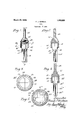
These, and such" other obj ects" as may hereinafter appear; are attained by the novel construction; combination, and arrangement of the several elements Which constitutefltlie tool and chuck, t\'v 'o fo'rms' of 'tools"being shown the attacheddraWinghereby made a par-tot thisap'plication, and in which Figure 1 is an elevatiom'p'artlyiin section, of the improved chuckan'd a toolassernbled therein, a 'paijtof the 'chuckfbeing broken other paijtofth'echuck;'- I Figureflfis 'a"loi'1'gi'tudinal section on the line 2 2 ofrigureiy I Figurefi is a transverse sectionbn the line of Figure 1'; I v
Figure 4 is" 'a longitudinalse'ctiom similar to Figure 2, of a modified form ofthe tool; and i V Figure 5 is a transverse section of $11011 d fied r rpf l-g. H s
Like: reference characters are used to designate similar parts in the drawing and in the description' of the invention which follows. a v
The tool hereinafter described adapted to be' used in a chuck. The chuck forms a holding portionforthe parts of the tool and is therefore essential in" its operation huqkj s necessary gfore the: p me vtulle: tioning' ofthetools as is hereinafter pointed out. The tool itself isor'dinarily madein a plurality of parts, each constituting'ajsep'a rate and indepenclent tool element, the asmb y ft' e ind pe ent o l m b r pro d g "1 u q m l ip e ol; "ai g ally a tool which can n'ot'be'"duplicate'd an integral structure. 4
0 an nd r t ing 7 f e? n vel f i reference 4 should be had first to" Figures 1, 2 fend, 3 ffllth ld mwins The; huj s designated by the n imjeralf 1.0, and this compris sacylind l 'ody'f l having a ne stricted outer' end terminating in an open; nai 'oi g t li the lfl p foi the other end'of"tlie body of the chuck being threaded to receive af'cap or closure member 12. Said ca13f12hasja depending stem or shank" 13 which is adapted to be attached to the driven shaft or spindle ortother instruf mentality (not shown) whereby the .chuck 10 maybe rotatedat any, desired speed.) Any suitable motive power may be, applied 'to the a. I
shaft or spindle or otherapp'aratiis whereby to obtain the; desired speed for 'thechuck 10'. The cap' 12 has athre'aded flange portion adapted to be inserted'into' the rearend of thechuck 10, and thisportion of the 'cap may i 1 be holl'ewed outer otherwise shaped to pro- ;vide' r frictional or im 'o'ing'i'ng] engagement of the cap; 12 ,upb i the, enldf of the tool adaptedfto be co nllainedji i the chuck 10, the
distance which the capif 12 is forced into 'cliiiclr 1O deteT ninin the seem? by a. I I" I =hrml away to show the" mpinging act1on of the j'tool: mem ers; her nafler. to'Jbe ass: a in ces. saia chtek 1g. Onl 'two f s "orftypsfofftool's are sheets Tlie foriii oi ty ie'of'tooljshowniin lg res .1, 2andm3 diff,e s o the? Show i 1" Figurefle the m nner of its assembly.
Of course thef operatingifr ortioni of the @601 or 'teol parts may"b,e"modified'to mjetan particula i edn iti 3 5 01.. he {shown i and it consists of a plurality of angularly cutting portion is trough-like or spooned,
each longitudinal edge being adapted to provide a cutting edge, and the end edge also providing a cutting part.
The upper portion or section 16 of the tool members is adapted to be held within the chuck 10. Said upper part 16 comprises two sections, one a thickened portion indicated 17, which is adapted'to project outwardly of the chuck body 10 and from which the tool part depends. The other enlarged portion 18 has two flat sides 19 and 20 which are perpendicular to one another, and a rounded intermediate side or surface 21, which comprises a quadrant or a segment of a circle.
The sides 19 and 20 are in alignment with the body portion of the part 17, while the rounded surface 21 provides a'fiange adapt,- ed to engage the constricted end 11 of the chuck 10. -This flange prevents the tool,
parts from being forced out of the body' of the chuck 10 when the cap 12 is firmly secured therein, and provides for the secure seating of said parts in said chuck 10. Four tools, 14 when placed together comprise a complete circle if the segmental surfaces ofthe sides 21 are considered. The angle of the cutting portion 15 with respect to the enlarged portions 17 and 18 is such that the cutting surfaces or cutting portions 15 are angularly disposed one with respect to the other whereby a crossed S effect is obtained in transverse cross section at the outer end of the tool. I The tool 14 is a most effective carving and cutting device, and is adapted to be routedv through wo od and other materials for the purpose of removing surplus material, for cutting wide grooves, andfor other purposes. I u The most casual inspection of the combination tool disclosed in igures 1, 23nd. 3 will show a device which is not capableof being manufactured asan integral member except under the greatest of cost. It is even doubtful whether such a tool could be manu factul'ecl and successfully operated as an in tegral member. The combination disclosed therefore, provides means for the production of new tools l aving'higher efficiency than present tool structures and many. new and diversified uses. When the cap 12 is screwed into the chuck 10, the tool members l4 are held against displacement. They mayiwork loose, but no damage can come therefrom before the deri e s {rhi fih pqhw s. be isemp eyed may be stopped. The tools 14, in practice, do not often work loose.
A second form of tool is shown in- Figure 4. In that illustrated form of the invention,'the cutting tool 14 has parallel sides, its structure being unlike that of the tool shown in Figures 1, 2 and 3, in that there dicular flat sides 23 and 24, and a rounded.
Said filling in part 22 is interchangeable and reversible, with respect to its ends, but one side 23 has a shorter radius than the other side 24, the side with the-longer radius being adapted to rest against'the broader side of a tool 14 The arrangement of the filler members 22 and the toolsli is clearly shown in Figure 4. In the manner indicated a useful assembly of tools is obtained, and. thevcost of the individual cutting tools may be less than that for the individual cutting tools shown in Figures 1, 2 and 3. For convenience of assembly, of course, the arrangement shown in Figure 4 is not'equal to that shown iii-the preceding figures, but for efliciency, the results obtainable therewith are substantially the same asthe results obtained in the first form of the invention described.
The filling in member used in an assembly is always placed against the body of a tool 14*. The impinging force of the cap 12 in the chuck 10 against the filler and the tools separated thereby provide for secure attach ment for the tool 14 within the chuck 10.
It is quite manifest that other tools, could be substituted for those here shown and each could have its. own specific utility, and that the number of active tool parts could be from two up, but preferably three, four, or six. I
The drawing illustrates the simple means for providing a multiple tool having many useful characteristics at the cost of a few simple tools,a decided advantage in tool making and tool using.
.The principal use for a tool. as illustrated is toremm'e surplus wood. It may be used both as a roughing orfinishing tool. Much time will be saved inavoiding the changing of tools because of. the double utility of thisarticlc;
As noted the tools may be made to form i when assembled (with or without filling members). a member circular in cross section. The tool may be formed as a segment of circular stock 01' as the segment of a circle. 1
What I claim as new and desire to secure by Letters Patent of the United States, is
1. In a wood-Working tool, the combination with a collar having a constricted opening therein communicating with the bore thereof, complemental cutting elements, each element terminating in an enlarged head complemental to each other in embracing relation with the bore of said collar to abut the constriction therein, and a shank adjustably associated With said collar to retain said complemental cutting elements in rigid relation.
2. In a wood-Working tool, the combination With a collar having a constricted opening therein communicating with the bore thereof, complemental cutting elements,each
element terminating in an enlarged head complemental to each other in embracing relation with the bore of said collar to abut the constriction therein, and a shank in threadedengagement with said collar to maintain said complemental cutting elements in rigid relation.
3. In a wood-Working tool, the combination with a collar having a constricted opening therein communicating with the bore thereof, complemental cutting elements, each element terminating in an enlarged head complemental to each other in embracing re lation With the bore of said collar to abut the constriction therein, a cap in threaded association with said bore to retain said cutting elements in rigid relation, and a shank fixed to said cap.
FRANK J. WIDMAN.
Priority Applications (1)
| Application Number | Priority Date | Filing Date | Title |
|---|---|---|---|
| US148797A US1663225A (en) | 1926-11-17 | 1926-11-17 | Tool |
Applications Claiming Priority (1)
| Application Number | Priority Date | Filing Date | Title |
|---|---|---|---|
| US148797A US1663225A (en) | 1926-11-17 | 1926-11-17 | Tool |
Publications (1)
| Publication Number | Publication Date |
|---|---|
| US1663225A true US1663225A (en) | 1928-03-20 |
Family
ID=22527427
Family Applications (1)
| Application Number | Title | Priority Date | Filing Date |
|---|---|---|---|
| US148797A Expired - Lifetime US1663225A (en) | 1926-11-17 | 1926-11-17 | Tool |
Country Status (1)
| Country | Link |
|---|---|
| US (1) | US1663225A (en) |
Cited By (4)
| Publication number | Priority date | Publication date | Assignee | Title |
|---|---|---|---|---|
| US2695043A (en) * | 1948-11-12 | 1954-11-23 | Abraham A Schauer | Planing tool for the manufacture of spirallike bodies |
| US2840128A (en) * | 1957-05-10 | 1958-06-24 | George L Slusser | Reversible action cutting bit assembly |
| US2920663A (en) * | 1958-05-12 | 1960-01-12 | Knick March Engineering Inc | Power-operated bevel edge cutter |
| US3383766A (en) * | 1966-12-08 | 1968-05-21 | Falcon Tool Company Inc | Cutter assemblage having four selectively usable single lip cutters |
-
1926
- 1926-11-17 US US148797A patent/US1663225A/en not_active Expired - Lifetime
Cited By (4)
| Publication number | Priority date | Publication date | Assignee | Title |
|---|---|---|---|---|
| US2695043A (en) * | 1948-11-12 | 1954-11-23 | Abraham A Schauer | Planing tool for the manufacture of spirallike bodies |
| US2840128A (en) * | 1957-05-10 | 1958-06-24 | George L Slusser | Reversible action cutting bit assembly |
| US2920663A (en) * | 1958-05-12 | 1960-01-12 | Knick March Engineering Inc | Power-operated bevel edge cutter |
| US3383766A (en) * | 1966-12-08 | 1968-05-21 | Falcon Tool Company Inc | Cutter assemblage having four selectively usable single lip cutters |
Similar Documents
| Publication | Publication Date | Title |
|---|---|---|
| US2046837A (en) | Means for uniting a screw with a driver | |
| US984323A (en) | Drilling-tool. | |
| DE202019101214U1 (en) | Tool device for a machine tool | |
| US1350241A (en) | Cold-chisel | |
| US1663225A (en) | Tool | |
| US3360023A (en) | Woodworking tool | |
| US2337440A (en) | Flexible handle for tools | |
| US849681A (en) | Putty-remover. | |
| US374701A (en) | Wood-screw | |
| US2700549A (en) | Tool for demolition machines | |
| DE1627419C3 (en) | Method and device for the non-cutting production of separating slots on the shank of blind rivets | |
| US433078A (en) | Cutting-tool and handle | |
| US981243A (en) | Mining-bit. | |
| US1755489A (en) | Self-drilling expansion shell | |
| US1533547A (en) | Slotting tool | |
| US870971A (en) | Device for cutting key-seats or the like. | |
| US246846A (en) | wilde | |
| US895387A (en) | Channeling-tool. | |
| US1191176A (en) | Tie-cutter. | |
| US587110A (en) | Nut-lock | |
| US305035A (en) | lytle | |
| US1243504A (en) | Broaching-tool. | |
| US637495A (en) | Milling-cutter tooth. | |
| JPS6129405B2 (en) | ||
| US628530A (en) | Rock-drill and rock-drill bit, &c. |