US1663223A - Adjustable reamer - Google Patents
Adjustable reamer Download PDFInfo
- Publication number
- US1663223A US1663223A US477104A US47710421A US1663223A US 1663223 A US1663223 A US 1663223A US 477104 A US477104 A US 477104A US 47710421 A US47710421 A US 47710421A US 1663223 A US1663223 A US 1663223A
- Authority
- US
- United States
- Prior art keywords
- sleeve
- stock
- cutter
- bore
- reamer
- Prior art date
- Legal status (The legal status is an assumption and is not a legal conclusion. Google has not performed a legal analysis and makes no representation as to the accuracy of the status listed.)
- Expired - Lifetime
Links
- 238000010276 construction Methods 0.000 description 3
- 101100379079 Emericella variicolor andA gene Proteins 0.000 description 2
- 238000004519 manufacturing process Methods 0.000 description 2
- 101100289061 Drosophila melanogaster lili gene Proteins 0.000 description 1
- 238000005259 measurement Methods 0.000 description 1
Images
Classifications
-
- B—PERFORMING OPERATIONS; TRANSPORTING
- B23—MACHINE TOOLS; METAL-WORKING NOT OTHERWISE PROVIDED FOR
- B23D—PLANING; SLOTTING; SHEARING; BROACHING; SAWING; FILING; SCRAPING; LIKE OPERATIONS FOR WORKING METAL BY REMOVING MATERIAL, NOT OTHERWISE PROVIDED FOR
- B23D77/00—Reaming tools
- B23D77/02—Reamers with inserted cutting edges
- B23D77/04—Reamers with inserted cutting edges with cutting edges adjustable to different diameters along the whole cutting length
- B23D77/042—Reamers with inserted cutting edges with cutting edges adjustable to different diameters along the whole cutting length by means of oblique planes
-
- Y—GENERAL TAGGING OF NEW TECHNOLOGICAL DEVELOPMENTS; GENERAL TAGGING OF CROSS-SECTIONAL TECHNOLOGIES SPANNING OVER SEVERAL SECTIONS OF THE IPC; TECHNICAL SUBJECTS COVERED BY FORMER USPC CROSS-REFERENCE ART COLLECTIONS [XRACs] AND DIGESTS
- Y10—TECHNICAL SUBJECTS COVERED BY FORMER USPC
- Y10T—TECHNICAL SUBJECTS COVERED BY FORMER US CLASSIFICATION
- Y10T408/00—Cutting by use of rotating axially moving tool
- Y10T408/83—Tool-support with means to move Tool relative to tool-support
- Y10T408/85—Tool-support with means to move Tool relative to tool-support to move radially
- Y10T408/858—Moving means including wedge, screw or cam
- Y10T408/8588—Axially slidable moving-means
- Y10T408/85892—Screw driven wedge or cam
- Y10T408/85894—Annular wedge-collar
- Y10T408/858945—Axially spaced tool-retaining collars
Definitions
- 'Ihis invention relates to expansible reamers for reaming out circular holes or hollow surfaces such as the Babbitt bearings, bushings and the like for journal'bearings of machinery.
- the invention is an improvementinthe art in that I provide in combination witha stock and a cutter xed against rotation on the'stock; a sleeve having an excentric bore and a' side opening through which said cutter extends; and lin practice I provide for such stock a plurality of such sleeves to'form a single kit or outfit, the outside diameters of said sleeves respectively being different and the bore being of the vsame diameter and located in each instance at the same distance -from the outside of the opening through which the cutter extends.
- the tool is easily adf justable to cut a hole or opening to a micrometric dimension, the cutting edge of the cutter always extending the predetermined distance from the axis of the stock, but at different distances from the actual or produced trace of the sleeve opposite to the openings through which the cutter projects.
- a principle of the invention is that the portion of the periphery ofvr the sleeve which supports the thrust of the cutter edge, determines the effective diameter of the reamer; and the distance may be-changed by changing sleeves or by .expanding one sleeve; and thel extent of such expansion may be de'- termined with micrometrio precision by bringing the sleeve to the exact adjustment along a taper stock.
- This expansion of the sleeve may be accomplished in vvarious ways and in some instances the cutter maybe seated on a taper stock that is excentric to .and supported by an expansible sleeve against thrust transverse to the axis of the reamer, and may extend radially through one wall of the sleeve and be supported by an internal excentric tapered stock; means being provided whereby the expansion of the sleeve may be eff ected in such manner as to increase the diameter of the reamer from the cutter edge to the bearing trace opposite said' cutter edge.
- the invention may be applied by changing sleeves at each change of diameter. Such application of the invention, however requires a different sleeve for each size of hole.
- the invention includes various forms of construction whereby thel variation o-"the diameter of the reamer is effected without vadjusting the cutter relative to the axisof the shank of the tool. This is ,done by an excentric arrangement of stock and sleeve.
- myinvention in a reamer of the class which is station ary while the bearing tobe reamed out is manually applied to the reamer, myinvention includes a taper stock, acutter abutting the stock, and a sleeve adapted to be expanded by the taper stock, Landfarranged to form a bearing for the tool opposite to the cutting edge; one longitudinal trace of the taper stock being parallel to the axis ofthe sleeve, and consequently to the external longitudinal trace of the vsleeve which forms the thrust bearing of the cutter when the sleeve is mounted on the stock.
- An ,object of the invention is to provide a simple adjustablereamer inA which the adjusting devices are inexpensive and adapted to use with a single stock with wide rangefof diameters, and adapted tobe adjusted with micrometric accuracy.
- An object is to provide a practical reamer in which a single stoclrwith a single cutter can be employed to ream holes of diierent sizes without adjusting the cutter relative to the stock.
- the invention includes the taper stock in combination with a cutter and meansfto hold the cutter non-rotatable on,and at vdiii'erer'it positions longitudinally of, the stock; and in order to produce the same in the most direct and simple manner, and in one implement, with' considerable range oi adjustability, the holding rmeans comprises an expansible cylindrical sleeve having a taper bore, which fits on the stock and the axis of which bore is oblique to the axis of the sleeve, and nuts turning.; on the axisof the stock, and adapted to adjust the sleeve lon# gitudinally of the stock.l d
- the sleeve may beunitary or 'may consistV of a set of splints or .staves held together by nuts screwed on the stock to embrace splints or staves.
- the stock is provided with alongitudinal key-way and the cutter is firmly seated in said key-wayand projects from the periphery of the stock loo the
- each ofV said sleeves with one exception, must have an excentric bore.
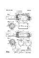
- Figure 1 is a side view of the adjustable reamer with sleeve and nuts in axial section.
- Fig. 2 is a section on line 02, Fig. 1.
- Fig. 3 is a side elevation of the sleeve shown in section in Fig. 1.
- Fig. 4 is a view analogous to Fig. 1, showing a sectional sleeve formed of longitudinal splints held together by socketed nuts on lthe stock.
- Fig. 5 is a section on line m5, Fig. 4.
- Fig. 6 is an end view of .an expansible sleeve of a diameter adapted to be applied .to either of the stocks shown inv Figs. 1
- Fig. 6 is an end view of an expansible sleeve similar to Fig. 6, except as to cutting element proportions.
- Fig. 7 is a view of the entering end of the tool shown in Figs. 1 and 2.
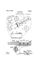
- Fig. 8 is a view partly in perspective and partly in end elevation and partly in longi tudinal section of an adjustable'underreamer constructed in accordance with this invention embodied in a stock anda set of six sleeves of different diameters, some of said sleeves being in end elevation and some in longitudinal section.
- Fig. 9 is a longitudinal section on linc indicated at Fig. 10, of the assembled tool shown in Fig. 8.
- Fig. 10 is a cross section'on line w1", Fig. 9.
- shank 1 may be of any desired construction and extends from the angular tip 2 to the threaded portion 3 of the stock 4, the axis 5 of which is oblique to the produced axis G'of the shank.
- Said stock is provided Vwith the threaded portions 3 and 7 adapted to seat the sleeve adjusting nuts 8, 9 that have conical seats 10, 11 accommodating the beveled ends 12 and 13 of the expansible sleeve, various forms of which may be provided.
- the sleeve is unitary and comprises a cylindrical body 14 having a taper bore 15, the longitudinal trace 16 of which is parallel to the produced axis 6 of the stock.v
- the longitudinal thrust or bearing trace 17 of the sleeve is4 also parallel to the produced axis 6; and the nuts 8 and 9 are screwed onto the threaded portions 3 and 7 until they engage the conical ends 12 and 13 of the sleeve.
- the sleeve may be constructed of any material Ahaving a degree of resiliency and is provided on the side opposite the bearing trace v17 with 'a slot 18 so as to allow the sleeve to expand when shoved from the entering end toward the shank vend of the stock.
- the slot 18 is adapted to accommodate a cutter 19, the cutting edge 20 of which projects freely through said slot.
- the heel of the cutter is seated in a groove 21 inthe stock 4 and it is evident from the foregoing that if the sleeve is shifted toward the shank, it will be expanded; and that the portion of the sleeve between the contacting or thrust bearing trace 17 and the axis of the stock, will be increased; and that increase will depend upon the amount the sleeve is shifted along the stock.
- the shifting for expansion may be accomplished accurately by loosening nut 8 and tightening the nut 9 to move the sleeve back. This loosening and tightening can be conducted and measurements be taken by a gage, and the diameter of the hole Vto be reamed can thus be exactly determined.
- longitudinal slots .22 are provided along the perimeter of the sleeve and these .may be of greater or less ldepth depending upon the character of the material of which the sleeve is made, it being intended that the sleeve will be capable of expansion to a predetermined diameter from which it will return when the expanding force is withdrawn.
- the slots may in manufacture be deepened until they entirely sever the sleeve into a number of splints as at 23 in Fig. 5, and each of these splints may be constructed in practically the same terminal contour as vwith the forms shown in Figs. 1, 3 and 6.
- Rotation of the sleeve upon the stock 4 is prevented by some suitable means which are indicated as of two different forms, in addition to the abutting of the sleeve on the cutter.
- Veach splint 23 is provided with'a tongue 27 for thesame purpose as key 24 of the other views.
- Figs. 8 -9 and 10 31 is straight. and fits on the stock and has a longitudinall thrust bearing trace 17 diametrically opposite the cutter seat to contact with the wall of the hole being reamed; and the cutter 19 is seated in said slot, and projects through the slot 32 of the sleeve with its cutting edge diametrically opposite the f thrust trace 17.
- the eccentricity ot' the bore determines the diameter of the hole that may be reamed with said sleeve and stock.
- These sleeves are detachably secured by over-hang retainers, 33, 34, one of which may be integral with and the other screwed onto the stock; or both may be screwed onto the stock as in Figs. 1 and el. y i
- a reamer comprising a stock; a cutte fixed against rotation on the stock; and a sleeve having a bore eccentric to the outside diameter of the sleeve and adaptedrto fit said stock, said sleeve also having a side opening to allow the cutter to project beyond the side of the sleeve when said sleeve is on the stock, the diameter of said sleeve determining the diameter of the hole that may be reamed with said stock and sleeve.
- a sleeve adapted for use in a reamer outfit, said sleeve having an opening in one side and having a bore open to said opening and eccentric to the sleeve.
- An adjustable reamer comprising a cylindrical sleeve having a taper bore, the longitudinal trace of one side of which bore is parallel to thelongitudinal trace of the adjacent produced periphery ofthe sleeve; said sleeve being slotted for the purpose ot allowing it to expand; a taper stock adapted to the bore of said sleeve and provided with a cutter seat; a cutter supported by said cutter seat and extending through the wall outside diameter ot said of the sleeve and having a cutting edge that is parallel to the axis ot' the sleeve; and adjustable means for fixing the sleeve. at difierent ⁇ positions along the stock.
- An adjustable reamer comprising a taper stock and a shank therefor, said stock beingprovided with a longitudinal groove forming a seat for a cutter, the axis of said stockbeing oblique to the produced axis of the shank; a cutter seated in said seat and having a cutting edge parallel to the produced axis of the shank; an expansible cylindrical sleeve having a taper bore slidably and ,non-rotatably mounted upon the stock, andA also having a slot through which the cutter seated in the seat in the stock may project; said'sleeve being non-rotatable on thestock; and means for adjusting the sleeve along the stock.
- An 'adjustable lreamer comprising a taper stock and a shank therefor, said stock being provided with a longitudinal groove forming a seat Jfor acutter; the axis of said stock being oblique to the produced axis of the shank, and the cutter seatbeing on that side-of the stockfarthest removed from said produced axisof the shank; a cutter seated in said cutter seat and having a cutting edge parallel to the produced axis of the shank; an expansible Vcylindrical sleeve having a taper bore and slidably and non-rotatably mounted upon the stock, and also having a slot through the side nearest the axis of said bore through which slot the cutter seated in the seat in the stock may project; and means cooperating ⁇ with the stock for holding the sleeve in fixed relation thereto at dierent adjustments on the stock.
- a reamer comprising a stock; a cutter fixed against rotation on the stock, and a lili' i' sleeve adapted tobefmounted on said stock and having av slotvto allow the edge of the sleeve through which said' cutter extends, said sleeve being provided with a thrust bearing trace diametrically opposite' tov the edgeI of the cutter, saidy sleeve forming the bearing at one side of the hole beingreamed, While the cutter operates diametrically opposite this bearing, said sleeve being adapted to filly the finished portion of the hole and being detachable from the stock forl the purpose of interchange ⁇ with another sleeve of. different diameter;
- a reamer comprising" aA stock; a cutter fixed against rotation on the stock, and a sleeve having any eccentric bore fitting the' stock and also having a slot through which the cutter extends' andl having ai thrust'bearing ⁇ trace diametrically opposite the cutting edge of. said cutter, said sleeve forming the bearing at one side of. theholebeing reamed,
- a reamer comprising a' cylindrical stock; a cutter fixed againstrotation on the stock, and a cylindrical sleeve having an eccentric cylindrical bore fitting the stock and14 also having a slot through' which the cutter extends and having' a thrust bearing trace diametrically opposite the cutting edge of said cutter, saidA sleeve forming the bear-- ing at one side of the hole being reamed, while thev cutter operatesl diametrically opposite this bearing, andA said sleeve being adapted to' fill the finished portion of' the hole.
- An adjustable reamer comprising a cutter, astock therefor and a; sleeve adaptedk to be mounted on the stock and to provide a support along the side opposite the cutting edge of the cutter, the axis of the stock being oblique to the axis of the sleeve.
- a taper stock, and a cutter on said stock Provided with a cutting edge; av sleeve having, a bore adapted to fit said stock, said bore being 1.
- said sleeve also yhaving; ani opening for the cutting edge of saidvcutter; and meansl formovingisaid sleevevlongitudinally on said stock to increase and decrease the distance ⁇ betweensaid cutting edge and theoutside of the sleeve opposite said opening.V Y
- ' sleeve having a bore eccentric to the outside diameter of the sleeve and adapted to fit ysaid stock', and said sleeve having? a side opening to allow the cutter to project beyond the side of the sleeve when the sadf sleeve is on the stock.
- a reamer outfit comprising a stock;v a cutter. fixed against rotation on the stock; and a plurality of sleeves of different outside diameter, each having a bore eccentric to the outside diameter ofthe sleeve and ⁇ adaptedfto ⁇ fit said stock, each sleeve'having a side opening to allowthe cutter toV project around the side of thefsleeve when the sleeve" is on the stock, and the various sleeves at said opening being of uniform thickness and ofvarying thickness at the side opposite to- HJALMAR THoMesoN.
Landscapes
- Engineering & Computer Science (AREA)
- Mechanical Engineering (AREA)
- Milling, Broaching, Filing, Reaming, And Others (AREA)
Description
March 2o, 1928. 1,663,223 H. THoMAsoN ADJUSTABLE REAMER 1,663,223 H. THoMAsoN ADJUSTABLE BEAMER March 20, 1928.l
Original Filed June 13, 1921 2 Sheets-Sheet 2 u .ai
36 lrwenfor.
[L17/dinar oma aon ML2/265s: i769 fm MMM Patented ar. 20, n 1928.,
ai i j sir HJALMAR rH'oMAsoN, or Los ANGELES,` c.ALrEorn\`1A,y As'sre'r'no'a ro sH'ErARp- @Hermsen co., on Los ANGELES, oALiEoRErA, eorrrosn'n or A. M sHEPARn AND HJALMAR THOMASON.
ADJUSTABLE BEAMER.
Application filedV June 13, 1921, Serial No. 477,104. Renewed` August 22, 1927.
'Ihis invention relates to expansible reamers for reaming out circular holes or hollow surfaces such as the Babbitt bearings, bushings and the like for journal'bearings of machinery.
The invention is an improvementinthe art in that I provide in combination witha stock and a cutter xed against rotation on the'stock; a sleeve having an excentric bore and a' side opening through which said cutter extends; and lin practice I provide for such stock a plurality of such sleeves to'form a single kit or outfit, the outside diameters of said sleeves respectively being different and the bore being of the vsame diameter and located in each instance at the same distance -from the outside of the opening through which the cutter extends. By this construction and arrangement, the tool is easily adf justable to cut a hole or opening to a micrometric dimension, the cutting edge of the cutter always extending the predetermined distance from the axis of the stock, but at different distances from the actual or produced trace of the sleeve opposite to the openings through which the cutter projects.
A principle of the invention is that the portion of the periphery ofvr the sleeve which supports the thrust of the cutter edge, determines the effective diameter of the reamer; and the distance may be-changed by changing sleeves or by .expanding one sleeve; and thel extent of such expansion may be de'- termined with micrometrio precision by bringing the sleeve to the exact adjustment along a taper stock.
This expansion of the sleeve may be accomplished in vvarious ways and in some instances the cutter maybe seated on a taper stock that is excentric to .and supported by an expansible sleeve against thrust transverse to the axis of the reamer, and may extend radially through one wall of the sleeve and be supported by an internal excentric tapered stock; means being provided whereby the expansion of the sleeve may be eff ected in such manner as to increase the diameter of the reamer from the cutter edge to the bearing trace opposite said' cutter edge. j
In a preferred form the invention may be applied by changing sleeves at each change of diameter. Such application of the invention, however requires a different sleeve for each size of hole.
The invention includes various forms of construction whereby thel variation o-"the diameter of the reamer is effected without vadjusting the cutter relative to the axisof the shank of the tool. This is ,done by an excentric arrangement of stock and sleeve.
In a reamer of the class which is station ary while the bearing tobe reamed out is manually applied to the reamer, myinvention includes a taper stock, acutter abutting the stock, and a sleeve adapted to be expanded by the taper stock, Landfarranged to form a bearing for the tool opposite to the cutting edge; one longitudinal trace of the taper stock being parallel to the axis ofthe sleeve, and consequently to the external longitudinal trace of the vsleeve which forms the thrust bearing of the cutter when the sleeve is mounted on the stock.
An ,object of the invention is to provide a simple adjustablereamer inA which the adjusting devices are inexpensive and adapted to use with a single stock with wide rangefof diameters, and adapted tobe adjusted with micrometric accuracy.
An object is to provide a practical reamer in which a single stoclrwith a single cutter can be employed to ream holes of diierent sizes without adjusting the cutter relative to the stock.
The invention includes the taper stock in combination with a cutter and meansfto hold the cutter non-rotatable on,and at vdiii'erer'it positions longitudinally of, the stock; and in order to produce the same in the most direct and simple manner, and in one implement, with' considerable range oi adjustability, the holding rmeans comprises an expansible cylindrical sleeve having a taper bore, which fits on the stock and the axis of which bore is oblique to the axis of the sleeve, and nuts turning.; on the axisof the stock, and adapted to adjust the sleeve lon# gitudinally of the stock.l d
The sleeve may beunitary or 'may consistV of a set of splints or .staves held together by nuts screwed on the stock to embrace splints or staves. Y v
An Objectis to provide a 4reamer that `is simple and that permits ready assembly and disassembly. i j
In ythe preferred form the stock is provided with alongitudinal key-way and the cutter is firmly seated in said key-wayand projects from the periphery of the stock loo the
different diameters are employed, each ofV said sleeves, with one exception, must have an excentric bore.
Further objects of the invention are strength and ease of manufacture.
Other objects, advantages and features of invention may appear fromthe accompanying drawings, the subjoined detail description and the appended claims.
The accompanying drawings illustrate the invention.
Figure 1 is a side view of the adjustable reamer with sleeve and nuts in axial section.
i Fig. 2 is a section on line 02, Fig. 1.
Fig. 3 is a side elevation of the sleeve shown in section in Fig. 1. v
Fig. 4 is a view analogous to Fig. 1, showing a sectional sleeve formed of longitudinal splints held together by socketed nuts on lthe stock.
Fig. 5 is a section on line m5, Fig. 4.
Fig. 6 is an end view of .an expansible sleeve of a diameter adapted to be applied .to either of the stocks shown inv Figs. 1
and 4.
' Fig. 6 is an end view of an expansible sleeve similar to Fig. 6, except as to cutting element proportions.
Fig. 7 is a view of the entering end of the tool shown in Figs. 1 and 2.
Fig. 8 is a view partly in perspective and partly in end elevation and partly in longi tudinal section of an adjustable'underreamer constructed in accordance with this invention embodied in a stock anda set of six sleeves of different diameters, some of said sleeves being in end elevation and some in longitudinal section.
Fig. 9 is a longitudinal section on linc indicated at Fig. 10, of the assembled tool shown in Fig. 8.
Fig. 10 is a cross section'on line w1", Fig. 9.
In each of the views the circular boreB is excentric to the sleeve which is generally indicated in the several views by S.
vReferring lirst to the characterV of tools shown in Figs. 1-7 shank 1 may be of any desired construction and extends from the angular tip 2 to the threaded portion 3 of the stock 4, the axis 5 of which is oblique to the produced axis G'of the shank. Said stock is provided Vwith the threaded portions 3 and 7 adapted to seat the sleeve adjusting nuts 8, 9 that have conical seats 10, 11 accommodating the beveled ends 12 and 13 of the expansible sleeve, various forms of which may be provided.
In Figs. 1, 2 and 3, the sleeve is unitary and comprises a cylindrical body 14 having a taper bore 15, the longitudinal trace 16 of which is parallel to the produced axis 6 of the stock.v The longitudinal thrust or bearing trace 17 of the sleeve is4 also parallel to the produced axis 6; and the nuts 8 and 9 are screwed onto the threaded portions 3 and 7 until they engage the conical ends 12 and 13 of the sleeve.
`The sleeve may be constructed of any material Ahaving a degree of resiliency and is provided on the side opposite the bearing trace v17 with 'a slot 18 so as to allow the sleeve to expand when shoved from the entering end toward the shank vend of the stock. The slot 18 is adapted to accommodate a cutter 19, the cutting edge 20 of which projects freely through said slot. The heel of the cutter is seated in a groove 21 inthe stock 4 and it is evident from the foregoing that if the sleeve is shifted toward the shank, it will be expanded; and that the portion of the sleeve between the contacting or thrust bearing trace 17 and the axis of the stock, will be increased; and that increase will depend upon the amount the sleeve is shifted along the stock. The shifting for expansion may be accomplished accurately by loosening nut 8 and tightening the nut 9 to move the sleeve back. This loosening and tightening can be conducted and measurements be taken by a gage, and the diameter of the hole Vto be reamed can thus be exactly determined.
In order to facilitate'and equalize the expansibility of thev sleeve, longitudinal slots .22 are provided along the perimeter of the sleeve and these .may be of greater or less ldepth depending upon the character of the material of which the sleeve is made, it being intended that the sleeve will be capable of expansion to a predetermined diameter from which it will return when the expanding force is withdrawn. l
In lieu of the unitary sleeve with or without the slots 22 the slots may in manufacture be deepened until they entirely sever the sleeve into a number of splints as at 23 in Fig. 5, and each of these splints may be constructed in practically the same terminal contour as vwith the forms shown in Figs. 1, 3 and 6.
Rotation of the sleeve upon the stock 4 is prevented by some suitable means which are indicated as of two different forms, in addition to the abutting of the sleeve on the cutter.
In Fig. 2 a key 24 is mounted in the l; ey ways 25, 26 so that revolution of the sleeve on the stock is impossible.
In the form shown in Fig. 5 Veach splint 23 is provided with'a tongue 27 for thesame purpose as key 24 of the other views.
In the form shown in Figs. 8, -9 and 10 31 is straight. and fits on the stock and has a longitudinall thrust bearing trace 17 diametrically opposite the cutter seat to contact with the wall of the hole being reamed; and the cutter 19 is seated in said slot, and projects through the slot 32 of the sleeve with its cutting edge diametrically opposite the f thrust trace 17.
The interchangeable tool shown in Figs. 8, 9 and 10, includes a set ot sleeves of difierent diameters as at a, Z), 0, d, e, 7; the walls ot the slots therein being uniform to iit the cutter and allot the same depth; and since the bores of the several sleeves are ot uniform diameter to iit the stock, each bore, with one exception, is eccentric to the periphery of its respective sleeve to increase or decrease the distance between the cutting edge 2O and the thrust bearing formed by the longitudinal trace 17, from the standard distance formed by the sleeve having a bore concentric with its periphery. Thus it may be seen that the eccentricity ot' the bore determines the diameter of the hole that may be reamed with said sleeve and stock. These sleeves are detachably secured by over-hang retainers, 33, 34, one of which may be integral with and the other screwed onto the stock; or both may be screwed onto the stock as in Figs. 1 and el. y i
The slot wall 35 is bevelled to give clearance to the cutter and the cutter is detachably mounted on the stock through means of the seat and cutter engagement shown.
vThese interchangeable sleeves are practically non-expansible and vary in diameter with micrometric precision so that adjustment of the tool to exact diameterof borefis quickly made by simply fastening onto the stock the specific sleeve therefor.
The stock is shown provided with holes 36 through which a punch may be. driven to displace the cutter when desired.
I claim- .f
l. A reamer comprising a stock; a cutte fixed against rotation on the stock; and a sleeve having a bore eccentric to the outside diameter of the sleeve and adaptedrto fit said stock, said sleeve also having a side opening to allow the cutter to project beyond the side of the sleeve when said sleeve is on the stock, the diameter of said sleeve determining the diameter of the hole that may be reamed with said stock and sleeve. n
2. A reamer outfit comprising a stock; a cutter fixed against rotation on the stock; and a plurality of sleeves of different outside diameters each having a bore eccentric to the outside diameter ot the sleeve and adapted to iit said stock, eachsleeve having a side opening to allow the cutter to project beyond the side of the sleeve when the sleeve is on they stock, the varioussleeves at said' opening being of .uniform thickness and being ofvarying thicknesses at the side opposite said side opening to enable the 'operator to ream various sized bores by simply chang.
ing the sleeve, the diameter ofjsaid sleeve.
determining- `the diameter of the holes that may be reamed with said stock and sleeves; and means for detachably fastening the sleeves interchangeably upon the stock.
3. A sleeve adapted for use in a reamer outfit, said sleeve having an opening in one side and having a bore open to said opening and eccentric to the sleeve.
L1. An adjustable reamer comprising a cylindrical sleeve having a taper bore, the longitudinal trace of one side of which bore is parallel to thelongitudinal trace of the adjacent produced periphery ofthe sleeve; said sleeve being slotted for the purpose ot allowing it to expand; a taper stock adapted to the bore of said sleeve and provided with a cutter seat; a cutter supported by said cutter seat and extending through the wall outside diameter ot said of the sleeve and having a cutting edge that is parallel to the axis ot' the sleeve; and adjustable means for fixing the sleeve. at difierent` positions along the stock.
5. An adjustable reamer comprising a taper stock and a shank therefor, said stock beingprovided with a longitudinal groove forming a seat for a cutter, the axis of said stockbeing oblique to the produced axis of the shank; a cutter seated in said seat and having a cutting edge parallel to the produced axis of the shank; an expansible cylindrical sleeve having a taper bore slidably and ,non-rotatably mounted upon the stock, andA also having a slot through which the cutter seated in the seat in the stock may project; said'sleeve being non-rotatable on thestock; and means for adjusting the sleeve along the stock. Y i
6. An 'adjustable lreamer comprising a taper stock and a shank therefor, said stock being provided with a longitudinal groove forming a seat Jfor acutter; the axis of said stock being oblique to the produced axis of the shank, and the cutter seatbeing on that side-of the stockfarthest removed from said produced axisof the shank; a cutter seated in said cutter seat and having a cutting edge parallel to the produced axis of the shank; an expansible Vcylindrical sleeve having a taper bore and slidably and non-rotatably mounted upon the stock, and also having a slot through the side nearest the axis of said bore through which slot the cutter seated in the seat in the stock may project; and means cooperating `with the stock for holding the sleeve in fixed relation thereto at dierent adjustments on the stock.
7. A reamer comprising a stock; a cutter fixed against rotation on the stock, and a lili' i' sleeve adapted tobefmounted on said stock and having av slotvto allow the edge of the sleeve through which said' cutter extends, said sleeve being provided with a thrust bearing trace diametrically opposite' tov the edgeI of the cutter, saidy sleeve forming the bearing at one side of the hole beingreamed, While the cutter operates diametrically opposite this bearing, said sleeve being adapted to filly the finished portion of the hole and being detachable from the stock forl the purpose of interchange` with another sleeve of. different diameter;
8'. A reamer comprising" aA stock; a cutter fixed against rotation on the stock, and a sleeve having any eccentric bore fitting the' stock and also having a slot through which the cutter extends' andl having ai thrust'bearing` trace diametrically opposite the cutting edge of. said cutter, said sleeve forming the bearing at one side of. theholebeing reamed,
whiley the cutter operates diametrically op-v positei thisfbearing, an'dsaid sleeve being adapted toj fill the finished portion of the hole.`
9. A reamer comprising a' cylindrical stock; a cutter fixed againstrotation on the stock, and a cylindrical sleeve having an eccentric cylindrical bore fitting the stock and14 also having a slot through' which the cutter extends and having' a thrust bearing trace diametrically opposite the cutting edge of said cutter, saidA sleeve forming the bear-- ing at one side of the hole being reamed, while thev cutter operatesl diametrically opposite this bearing, andA said sleeve being adapted to' fill the finished portion of' the hole..`
10. In a reamer, the combination ofi a stock;l a cutter seated inY said stock' and' in Vnon-rotatable relation thereto; a sleeve hav'- ing an' eccentric bore fitting the stock and provided with a slot through which said cutter projects, the` diameter of said sleeve determining the diameter of the hole thatY Y may be reamed with said stock and sleeve; and nuts screwed onto the stock andf overhanging the ends ofi the sleeve.
ll. An adjustable reamer comprising' ay stock, a cutter carriedV by the stock and-va cutter to project beyond the side of the sleeve when it is on the stock; the bore of said sleeve being equidistant throughout from the periphery of the' sleeve on the slotted side thereof andi being of a greater or' less diameter from the periphery ofl the sleeve on the side opposite the slot.
l2. An adjustable reamer comprising a cutter, astock therefor and a; sleeve adaptedk to be mounted on the stock and to provide a support along the side opposite the cutting edge of the cutter, the axis of the stock being oblique to the axis of the sleeve..
13. In an adjustable reamer, a taper stock, and a cutter on said stock Provided with a cutting edge; av sleeve having, a bore adapted to fit said stock, said bore being 1.
eccentric. to the outside diameter of saidl sleeve, said sleeve also yhaving; ani opening for the cutting edge of saidvcutter; and meansl formovingisaid sleevevlongitudinally on said stock to increase and decrease the distance` betweensaid cutting edge and theoutside of the sleeve opposite said opening.V Y
14. A reamer comprising, a stock; a cutter fixed against rotation onthe stock; vand a,
' sleeve having a bore eccentric to the outside diameter of the sleeve and adapted to fit ysaid stock', and said sleeve having? a side opening to allow the cutter to project beyond the side of the sleeve when the sadf sleeve is on the stock.
15.A reamer outfit comprising a stock;v a cutter. fixed against rotation on the stock; and a plurality of sleeves of different outside diameter, each having a bore eccentric to the outside diameter ofthe sleeve and` adaptedfto` fit said stock, each sleeve'having a side opening to allowthe cutter toV project around the side of thefsleeve when the sleeve" is on the stock, and the various sleeves at said opening being of uniform thickness and ofvarying thickness at the side opposite to- HJALMAR THoMesoN. f
Priority Applications (1)
| Application Number | Priority Date | Filing Date | Title |
|---|---|---|---|
| US477104A US1663223A (en) | 1921-06-13 | 1921-06-13 | Adjustable reamer |
Applications Claiming Priority (1)
| Application Number | Priority Date | Filing Date | Title |
|---|---|---|---|
| US477104A US1663223A (en) | 1921-06-13 | 1921-06-13 | Adjustable reamer |
Publications (1)
| Publication Number | Publication Date |
|---|---|
| US1663223A true US1663223A (en) | 1928-03-20 |
Family
ID=23894560
Family Applications (1)
| Application Number | Title | Priority Date | Filing Date |
|---|---|---|---|
| US477104A Expired - Lifetime US1663223A (en) | 1921-06-13 | 1921-06-13 | Adjustable reamer |
Country Status (1)
| Country | Link |
|---|---|
| US (1) | US1663223A (en) |
-
1921
- 1921-06-13 US US477104A patent/US1663223A/en not_active Expired - Lifetime
Similar Documents
| Publication | Publication Date | Title |
|---|---|---|
| US2913935A (en) | Tool holder | |
| US1204994A (en) | Compound tool. | |
| US2358608A (en) | Combination tool | |
| US1663223A (en) | Adjustable reamer | |
| US2891429A (en) | Bearing pocket boring tool | |
| US817042A (en) | Boring-tool, reamer, and the like. | |
| US2815688A (en) | Boring bar | |
| US2367560A (en) | Reamer | |
| US3323193A (en) | Cutting tool cartridge insert | |
| US2623422A (en) | Reaming tool with removable blades | |
| US3572183A (en) | Straight drill | |
| US1366733A (en) | Machine-reamer | |
| US1377495A (en) | Countersink | |
| US1451742A (en) | Expanding reamer | |
| US1232980A (en) | Counterboring-tool. | |
| US2545931A (en) | Stock cutting dowel forming tool | |
| US1347740A (en) | Reamer | |
| US842481A (en) | Reamer. | |
| US1451741A (en) | Expanding reamer | |
| US2362708A (en) | Cutter | |
| US914653A (en) | Reamer. | |
| US1113067A (en) | Reamer. | |
| US1022760A (en) | Tool-holder. | |
| US713064A (en) | Screw-plate. | |
| US1928014A (en) | Reamer |