US1663218A - Pressure carburetor-control device - Google Patents
Pressure carburetor-control device Download PDFInfo
- Publication number
- US1663218A US1663218A US142515A US14251526A US1663218A US 1663218 A US1663218 A US 1663218A US 142515 A US142515 A US 142515A US 14251526 A US14251526 A US 14251526A US 1663218 A US1663218 A US 1663218A
- Authority
- US
- United States
- Prior art keywords
- carburetor
- pressure
- diaphragm
- float
- chamber
- Prior art date
- Legal status (The legal status is an assumption and is not a legal conclusion. Google has not performed a legal analysis and makes no representation as to the accuracy of the status listed.)
- Expired - Lifetime
Links
- 210000002445 nipple Anatomy 0.000 description 16
- 239000003921 oil Substances 0.000 description 16
- 238000002485 combustion reaction Methods 0.000 description 9
- 239000000446 fuel Substances 0.000 description 6
- 238000010276 construction Methods 0.000 description 3
- 230000001050 lubricating effect Effects 0.000 description 3
- 230000008878 coupling Effects 0.000 description 2
- 238000010168 coupling process Methods 0.000 description 2
- 238000005859 coupling reaction Methods 0.000 description 2
- 241000220284 Crassulaceae Species 0.000 description 1
- 230000001419 dependent effect Effects 0.000 description 1
- 238000010790 dilution Methods 0.000 description 1
- 239000012895 dilution Substances 0.000 description 1
- 239000000314 lubricant Substances 0.000 description 1
- 239000010687 lubricating oil Substances 0.000 description 1
- 238000005461 lubrication Methods 0.000 description 1
- 238000004519 manufacturing process Methods 0.000 description 1
- 230000002093 peripheral effect Effects 0.000 description 1
Images

Classifications
-
- F—MECHANICAL ENGINEERING; LIGHTING; HEATING; WEAPONS; BLASTING
- F01—MACHINES OR ENGINES IN GENERAL; ENGINE PLANTS IN GENERAL; STEAM ENGINES
- F01M—LUBRICATING OF MACHINES OR ENGINES IN GENERAL; LUBRICATING INTERNAL COMBUSTION ENGINES; CRANKCASE VENTILATING
- F01M1/00—Pressure lubrication
- F01M1/18—Indicating or safety devices
- F01M1/20—Indicating or safety devices concerning lubricant pressure
- F01M1/22—Indicating or safety devices concerning lubricant pressure rendering machines or engines inoperative or idling on pressure failure
- F01M1/24—Indicating or safety devices concerning lubricant pressure rendering machines or engines inoperative or idling on pressure failure acting on engine fuel system
Definitions
- This invention relates to a novel pressure carburetor control device and consists of the matters hereinafter describedand more par ticularly pointed out in the appended claims.
- the invention relates to a device applicable to an internal combustion motor employing an oil pressure or circulating system for lubricating purposes and adapted to cut off fuel supply when the pressure in the lubricating system falls below a predetermined required level for lubrication.
- Theobject of the invention is to produce a device of the kind which is simple and cheap to manufacture, which may be readily and quickly applied to the several standard fuel-feed systems on the market, and which is positive and eflicient in operation.
- the many advantages of the invention will appear more fully as I proceed in my specification.
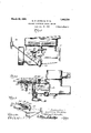
- Figure 1 is a view in side elevation representing an internal combustion motor with its carburetor fuel-feed line and oil pump for supplying lubricating oil .to the crank case.
- Figure 2 is a Vertical central section on an enlarged scale of the carburetor float chamber and of the improved pressure carburetor control applied thereto.
- Figure 3 is a perspective view of the pressure carburetor control device as it appears when separate from the carburetor float chamber ready for application thereto, parts being broken away to show the operation of concealed members.
- Figure 4 is a view of a carburetor, oil pressure line, gauge and the like, with my improved device applied, the carburetor being in this case of a different type than that shown in Figures 1, 2 and 3. p
- Figure 5 is a detail sectionalview on an enlarged scale through the carburetor float chamber and the pressure carburetor control device.
- Figure 6 is a part transverse section on an enlarged scale through Figure 5 in a plane indicated by, the line 66 in Figure 5.
- 10 lndicates the internal combustion engine of an ordinary automobile, 11 the inlet manifold therefor, 12 the carburetor; 13 indicates the oil pump adapted to supply lubricating 011 under pressure to the movable parts, and 14 indicates the usual oil gauge on the dash of the automobile; 15 indicates the float chamber of the carburetor, and 16 indicates the fuel supply pipe leading thereto; 17 indicates the float valve controlling the flow of fuel through the valve opening 18, and 19 indicates a float which controls the openmg of the float valve, the two being mounted at opposite ends of a lever 19 pivoted at 19 in a familiar manner.
- the right hand end of the base 20 is formed like the usualcover plate for the float chamber casing 15 and is provided with a tickler 21 and suitable screw openings for its attachment by means of screws 22 in the same way as said usual cover plate.
- the base'plate 20 is provided with a depending threaded nipple 23, to which is attached a pipe 24 connected by a suitable coupling 25 to the pipe 26 which leads to the oil gauge 14.
- the connection to the nipple 23 is made by suitable coupling 27.
- a circular plate 28 mounted with a circular recess 29 in its face next the base 20,
- duplex rib '33 On the top of the plate 28 and extending diametrically thereof towards a point in vertical alignment above the valve stem 17 of the carburetor there is provided an integral duplex rib '33.
- the members of said rib are closed upon each other at their inner ends as indicated at 34.
- the members of this duplex rib provide a channel in which is mounted a lever 35 pivoted on a pin 36 extending transversely between the members of the duplex rib 33 near the left hand end thereof. Near said pivot pin 36, but von the side towards the carburetor casing, a screw or pin 37 is carried by the lever 35. Said pin projects through an aperture in the plate 28 and engages the op diaphragm member 30.
- Diaphragm mem er 30 is reinforced in center, at point of contact with screw or pin 37.
- a second screw 38 which depends throughapertures in the plate 28 and the base 20to engage the end of the float valve operating lever 19 at the top end of the float valve itself 17;
- a coiled spring 39 interposed between the left hand end of the lever 35 and the top of the plate 28, being seated vin a suitablerecess formed therein, acts normally to liftsaid left hand end in such mannor as to depress theadjusting screw 38 to hold the float valve17 closed on its seat.
- the operator is thus notifiedof the trouble and cannot run the engine further without using the tickler 21 or lever 35 to introduce a fresh supply of fuel into the float chamber to start the engine.
- the two plates in this case are-of the same diameter and one of the two plates of the device, the top plate 28*,as illustrated in the drawings, is provided with a depending threaded nipple 40, which depends through a notch or opening 40 in the plate 20,
- a tubular member 41 externally threaded at its upper end to engage within the threaded nipple 40 and internally threaded at its bottom end to be screwed upon the usual threaded nipple 42 on the top cover plate 43 of the float casing 15 of the carburetor.
- the nipple 42 is the one through which the stem 17 of the float valve projects in this type of carburetor, the same being closedby a cap (not shown) screwed upon the nipple 42.
- Our device is applied as shown by removing the said cap and attaching it to the nipple 42.
- the tube 41 is lockedto the depending nipple 40 by a j amb nut 45.
- the adjusting screw orpin 38 carried at the right hand end of the lever 35 extends down through the tube41 toa position, to
- a pressure carburetor control device adapted to be applied to the float chamber of the carburetor of an internal combustion engine having a pressure feed or circulating oiling system, comprising means providing a diaphragm chamber, a diaphragm in said chamber, said diaphragm being subjected on one s1de to the pressure of said oiling system,
- a pressure carburetor control device adapted to be applied to the float chamber of the carburetor of an internal combustion enginehaving a pressure feed oiling system, comprising a structure formed to provide a diaphragm chamber, means for attaching said structure to the float chamber, a diameans connecting said diaphragm chamber to the oil pressure line, a lever fulcrumed to said structure and adapted normally to hold the float valve of the carburetor closed on its seat, and means interposed between said lever and said diaphragm adapted to raise said lever under the oil pressure against said diaphragm.
- a pressure. carburetor control device adapted to be applied to the float chamber of the carburetor of an internal combustion engine having a pressure feed oiling system, comprising two plates, one formed to provide a diaphragm chamber above'the other, said other plate having an aperture concentric with said chamber, a pipe connected in said aperture, a diaphragm in said-chamber, means for attaching the two plates to the float chamber, a lever fulcrumed to the plate structure above said diaphragm, devices taking" through said plates, one engaged with said diaphragm and the other adapted for engagement against the float valve in said phragm to the pressure thereof, said plates being provided with apertures beyond said diaphragm chamber and the one plate being provided with an aperture above said diaphragm, means for attaching said device as a whole to a carburetor float chamber with the first named apertures above the float valve therein, a spring-controlled lever fulcrumed to said device, and pins carried by said lever, one
- a pressure carburetor control device comprising a base plate having an aperture located vertically above said float valve, a second plate secured to said base plate, said two plates providing a diaphragm chamber between them at one side of said aperture, said base plate having a depending nipple concentric with and opening into said diaphragm chamber, a fitting connected in said oil pipe line and attached to said nipple, a diaphragm member located in said diaphragm chamber above said nipple, and a springcontrolled lever plvoted above said base plate and carrying screws or pins, one screw near its fulcrum engaged with one of the diaphragm members, and one remote from its fulcrum engaged with said float valve.
Landscapes
- Engineering & Computer Science (AREA)
- Mechanical Engineering (AREA)
- General Engineering & Computer Science (AREA)
- Lubrication Of Internal Combustion Engines (AREA)
Description
March 20, 1928. 1,663,218
- W. F. SCHULTZ ET AL I PRESSURE CARBURETOR CONTROL DEVICE Filed Oct. 18. 1926 2 Sheets-Sheet- 1 777751276604 Zawmnce YJZGASCJZQ March 20, 1928. 1,663,218
' W. F'. SCHULTZ ET AL PRESSURE CARBURETOR CONTROL DEVICE Filed Oct. 18, 1926 2 sheets-sheet 2 Jill!" 11W 1 v 1- Zqw/ence Wlwscize, #66365 J ZoZZLa/EFJbW/MZ Patented Mar. 20, 1928.
UNITED WILLIAM F. SCHULTZ AND LAWRENCE MASCHE, OF RIPON, WISCONSIN.
PRESSURE CARBURETOB-CONTROL DEVICE.
Application filed October 18, 1926. Serial No. 142,515.
This invention relates to a novel pressure carburetor control device and consists of the matters hereinafter describedand more par ticularly pointed out in the appended claims.
The invention relates to a device applicable to an internal combustion motor employing an oil pressure or circulating system for lubricating purposes and adapted to cut off fuel supply when the pressure in the lubricating system falls below a predetermined required level for lubrication. I
- Theobject of the invention is to produce a device of the kind which is simple and cheap to manufacture, which may be readily and quickly applied to the several standard fuel-feed systems on the market, and which is positive and eflicient in operation. The many advantages of the invention will appear more fully as I proceed in my specification.
In the drawings- Figure 1 is a view in side elevation representing an internal combustion motor with its carburetor fuel-feed line and oil pump for supplying lubricating oil .to the crank case.
Figure 2 is a Vertical central section on an enlarged scale of the carburetor float chamber and of the improved pressure carburetor control applied thereto.
Figure 3 is a perspective view of the pressure carburetor control device as it appears when separate from the carburetor float chamber ready for application thereto, parts being broken away to show the operation of concealed members.
Figure 4 is a view of a carburetor, oil pressure line, gauge and the like, with my improved device applied, the carburetor being in this case of a different type than that shown in Figures 1, 2 and 3. p
Figure 5 is a detail sectionalview on an enlarged scale through the carburetor float chamber and the pressure carburetor control device.
Figure 6 is a part transverse section on an enlarged scale through Figure 5 in a plane indicated by, the line 66 in Figure 5.
In the embodiment of our invention as illustrated herein we have shown a novel pressure carburetor control applied to the float chamber of the carburetor casing.- In Figures 1 to 3 the carburetor is one of the offset control type as the Marvel and the like carburetors. In. Figures 4 and 5 we have shown the device applied to a center control type as the- Stromberg and like carburetors.
Referring now to Figures 1 to 3, inclusive, 10 lndicates the internal combustion engine of an ordinary automobile, 11 the inlet manifold therefor, 12 the carburetor; 13 indicates the oil pump adapted to supply lubricating 011 under pressure to the movable parts, and 14 indicates the usual oil gauge on the dash of the automobile; 15 indicates the float chamber of the carburetor, and 16 indicates the fuel supply pipe leading thereto; 17 indicates the float valve controlling the flow of fuel through the valve opening 18, and 19 indicates a float which controls the openmg of the float valve, the two being mounted at opposite ends of a lever 19 pivoted at 19 in a familiar manner.
Instead of the cover plate for the float chamber casing 15, said casing is closed by a plate 20 which constitutes the base for our improved pressure carburetor control device.
The right hand end of the base 20 is formed like the usualcover plate for the float chamber casing 15 and is provided with a tickler 21 and suitable screw openings for its attachment by means of screws 22 in the same way as said usual cover plate.
At the left hand end of the base plate 20, so as to be located at one side of the float chamber casing 15, the base'plate 20 is provided with a depending threaded nipple 23, to which is attached a pipe 24 connected by a suitable coupling 25 to the pipe 26 which leads to the oil gauge 14. The connection to the nipple 23 is made by suitable coupling 27. Mounted on the top of the base 20 concentrically with the aperture of the nipple 23 is a circular plate 28 provided with a circular recess 29 in its face next the base 20,
which recess is also concentric. with the aperture of the nipple 23. Within the chamber 1 at their peripheral edges to insure a tight joint in the diaphragm chamber provldedby them.
On the top of the plate 28 and extending diametrically thereof towards a point in vertical alignment above the valve stem 17 of the carburetor there is provided an integral duplex rib '33. The members of said rib are closed upon each other at their inner ends as indicated at 34. .The members of this duplex rib provide a channel in which is mounted a lever 35 pivoted on a pin 36 extending transversely between the members of the duplex rib 33 near the left hand end thereof. Near said pivot pin 36, but von the side towards the carburetor casing, a screw or pin 37 is carried by the lever 35. Said pin projects through an aperture in the plate 28 and engages the op diaphragm member 30. Diaphragm mem er 30 is reinforced in center, at point of contact with screw or pin 37. At the right hand end, of the lever 35, in vertical alignment with the float valve 17 is carried a second screw 38 which depends throughapertures in the plate 28 and the base 20to engage the end of the float valve operating lever 19 at the top end of the float valve itself 17; A coiled spring 39 interposed between the left hand end of the lever 35 and the top of the plate 28, being seated vin a suitablerecess formed therein, acts normally to liftsaid left hand end in such mannor as to depress theadjusting screw 38 to hold the float valve17 closed on its seat.
This is the'normal position of the parts when the engine is idle, the oil pump is not operating and there is no pressure shown on the gauge 14 as existing in the system, including the pipe 26 and the pipe 24 connected to the diaphragm casing provided by the diaphragm members 30 and 31. Thus the sup ply of fuel to" the carburetor is cut off.
.VVhen the engine is running and by reason xofja-proper oil supply and the eflieient operyfitlIlQOf the oil pump, the required pressure is shown on the gauge 14, this pressure will be' exerted in the'diaphrag'm casing so that the upper diaphragm member 30, acting 1 against the bottom: end of the screw 37, will hold the lever 35 in. raised position and with it thescrew .38 at the right hand end thereof,
so that no. pressure is brought to bear by the "icontrol on the floatuvalve to interfere with ar of theoi lsupply, failure of proper oper- --at1onof the oil pump or other reason, the ."press'urenfadsinthe oil system sufliciently so. that the action of the spring 39 is suflicient to: depressthe right hand end of the f'-'leverl' 35 and cause the adjusting screw 38 TO force thexfloat valve down on its seat, the
--" *1; supply of-fueltoflthe Yfloat casing will be blocked and the engine will cease to run.
The operator is thus notifiedof the trouble and cannot run the engine further without using the tickler 21 or lever 35 to introduce a fresh supply of fuel into the float chamber to start the engine.
In Figures 4 and 5 we have shown the pressure carburetor control applied to a carburetor in which the float valve is placed at the center of the float. In said case the construction is in the main as before except for the form of the base plate, which, in this case, does not provide acover for the float cham ber. Corresponding parts are indicated by the same numerals as used before, but with the superscript x.
The two plates in this case are-of the same diameter and one of the two plates of the device, the top plate 28*,as illustrated in the drawings, is provided with a depending threaded nipple 40, which depends through a notch or opening 40 in the plate 20, In said nipple 40 is secured a tubular member 41 externally threaded at its upper end to engage within the threaded nipple 40 and internally threaded at its bottom end to be screwed upon the usual threaded nipple 42 on the top cover plate 43 of the float casing 15 of the carburetor. The nipple 42 is the one through which the stem 17 of the float valve projects in this type of carburetor, the same being closedby a cap (not shown) screwed upon the nipple 42. Our device is applied as shown by removing the said cap and attaching it to the nipple 42. The tube 41 is lockedto the depending nipple 40 by a j amb nut 45.
The adjusting screw orpin 38 carried at the right hand end of the lever 35 extends down through the tube41 toa position, to
.engage the top end of the float valve stem to the oil line is also in this case somewhat different, the pipe member 24 in this case being connected in series in the pipe line 26 that leads to the gauge 14 on the dash. The pipe 24 is provided with laterally disposed vertically spaced threaded nipples 45, 45 which are connected in the pipe line 26, 26 in any convenient manner. The operation here is the same as before.
The simplicity of construction and the ease and readiness of application of the improved pressure carburetor control device will be apparent to those familiar with the art from the foregoing description. When applied to a carburetor it. will preventflooding of the carburetor and combustion chamber of the motor with their objectionable results or dilution of the lubricant in the crank case and the difliculty in starting the motor. Since the float valve is closed on its seat when the motor is not running the device prevents leaking of the cazburetor valves and flooding of the carburetor when the motor is Inn idle. Sincethe device stops the engine when the oil pressure fails so that the en ine is not properly lubricated, the use of t e device saves the bearings andalso prevents scoring of cylinder walls and pistons, thus prolongs the life of the engine.
These and many other advantages and results followingfrom the use of a device of the kind will be manifest to those familiar with the operation and care of internal combustion motors.
Vhile in describing our invention we have referred to many details of construction and of arrangement of parts, it will be understood that the invention is to be in no way limited thereto except as may be pointed out in 'the appended claims.
We claim as our invention:
' 1. A pressure carburetor control device adapted to be applied to the float chamber of the carburetor of an internal combustion engine having a pressure feed or circulating oiling system, comprising means providing a diaphragm chamber, a diaphragm in said chamber, said diaphragm being subjected on one s1de to the pressure of said oiling system,
a spring-controlled lever fulcrum above the 'other side of said diaphragm, and devices phragm in said diaphragm chamber,
dependin from said lever, one engaged with said diap ragm and one adapted to be engaged against the float valve-head in said float chamber to make the opening movement of said float valve dependent upon the movement of said diaphragm.
2. A pressure carburetor control device adapted to be applied to the float chamber of the carburetor of an internal combustion enginehaving a pressure feed oiling system, comprising a structure formed to provide a diaphragm chamber, means for attaching said structure to the float chamber, a diameans connecting said diaphragm chamber to the oil pressure line, a lever fulcrumed to said structure and adapted normally to hold the float valve of the carburetor closed on its seat, and means interposed between said lever and said diaphragm adapted to raise said lever under the oil pressure against said diaphragm.
3. A pressure. carburetor control device adapted to be applied to the float chamber of the carburetor of an internal combustion engine having a pressure feed oiling system, comprising two plates, one formed to provide a diaphragm chamber above'the other, said other plate having an aperture concentric with said chamber, a pipe connected in said aperture, a diaphragm in said-chamber, means for attaching the two plates to the float chamber, a lever fulcrumed to the plate structure above said diaphragm, devices taking" through said plates, one engaged with said diaphragm and the other adapted for engagement against the float valve in said phragm to the pressure thereof, said plates being provided with apertures beyond said diaphragm chamber and the one plate being provided with an aperture above said diaphragm, means for attaching said device as a whole to a carburetor float chamber with the first named apertures above the float valve therein, a spring-controlled lever fulcrumed to said device, and pins carried by said lever, one engaged through the one aperture against said diaphragm and the other adapted to engage through the other aperture against the float valve in said float chamber.
5. In combination with an internal combustion engine having a pressure feed oiling system therefor and a carburetor for. supplying fuel thereto, said carburetor having a float chamber casing, a float valve and a float for controlling the operation of the same, a pressure carburetor control device comprising a base plate having an aperture located vertically above said float valve, a second plate secured to said base plate, said two plates providing a diaphragm chamber between them at one side of said aperture, said base plate having a depending nipple concentric with and opening into said diaphragm chamber, a fitting connected in said oil pipe line and attached to said nipple, a diaphragm member located in said diaphragm chamber above said nipple, and a springcontrolled lever plvoted above said base plate and carrying screws or pins, one screw near its fulcrum engaged with one of the diaphragm members, and one remote from its fulcrum engaged with said float valve.
In testimonythat we claim the foregoing as our invention, we afiix our signatures this 21 day of September, A. D. 1926.
. WILLIAM F. SCHULTZ. LAWRENCE -MASCHE.
Priority Applications (1)
| Application Number | Priority Date | Filing Date | Title |
|---|---|---|---|
| US142515A US1663218A (en) | 1926-10-18 | 1926-10-18 | Pressure carburetor-control device |
Applications Claiming Priority (1)
| Application Number | Priority Date | Filing Date | Title |
|---|---|---|---|
| US142515A US1663218A (en) | 1926-10-18 | 1926-10-18 | Pressure carburetor-control device |
Publications (1)
| Publication Number | Publication Date |
|---|---|
| US1663218A true US1663218A (en) | 1928-03-20 |
Family
ID=22500134
Family Applications (1)
| Application Number | Title | Priority Date | Filing Date |
|---|---|---|---|
| US142515A Expired - Lifetime US1663218A (en) | 1926-10-18 | 1926-10-18 | Pressure carburetor-control device |
Country Status (1)
| Country | Link |
|---|---|
| US (1) | US1663218A (en) |
Cited By (1)
| Publication number | Priority date | Publication date | Assignee | Title |
|---|---|---|---|---|
| US2751044A (en) * | 1952-08-21 | 1956-06-19 | Harris Joseph | Means for lubricating machinery |
-
1926
- 1926-10-18 US US142515A patent/US1663218A/en not_active Expired - Lifetime
Cited By (1)
| Publication number | Priority date | Publication date | Assignee | Title |
|---|---|---|---|---|
| US2751044A (en) * | 1952-08-21 | 1956-06-19 | Harris Joseph | Means for lubricating machinery |
Similar Documents
| Publication | Publication Date | Title |
|---|---|---|
| US2369397A (en) | Variable speed governor | |
| US2633146A (en) | Fuel pulsation dampener and pressure regulator | |
| US1473303A (en) | Fuel control for internal-combustion engines | |
| US1489348A (en) | Fluid-transfer device | |
| US2801621A (en) | Fuel-pump carburetor | |
| US1663218A (en) | Pressure carburetor-control device | |
| US1881939A (en) | Pumping mechanism | |
| US2294609A (en) | Pump | |
| US2310594A (en) | Primer for internal combustion motors | |
| US2317594A (en) | Fluid pressure device | |
| US2194007A (en) | Lubricant-feeding apparatus for internal combustion engines | |
| US1885436A (en) | Fluid transfer device | |
| US2028371A (en) | Fuel pump | |
| US2298756A (en) | Inverted pump | |
| US2469942A (en) | Control for fuel supply systems | |
| US1576889A (en) | Automatic fuel cut-out | |
| US2617640A (en) | Economizer mechanism for carburetors | |
| US2274532A (en) | Safety fuel system fob internal | |
| US2303532A (en) | Flow testing device | |
| US1812013A (en) | Fuel feeding system for internal combustion engines | |
| US2645466A (en) | Carburetor fuel system, including diaphragm valves | |
| US2746479A (en) | Fuel feeding device | |
| US2312817A (en) | Cylinder liner | |
| US1548590A (en) | Combined fuel valve and sediment bulb | |
| US2171209A (en) | Fuel pump for supercharged engines |