US1663213A - Piercing machine - Google Patents
Piercing machine Download PDFInfo
- Publication number
- US1663213A US1663213A US6482125A US1663213A US 1663213 A US1663213 A US 1663213A US 6482125 A US6482125 A US 6482125A US 1663213 A US1663213 A US 1663213A
- Authority
- US
- United States
- Prior art keywords
- piercing
- belt
- objects
- machine
- head
- Prior art date
- Legal status (The legal status is an assumption and is not a legal conclusion. Google has not performed a legal analysis and makes no representation as to the accuracy of the status listed.)
- Expired - Lifetime
Links
- 230000033001 locomotion Effects 0.000 description 17
- 240000008067 Cucumis sativus Species 0.000 description 5
- 238000011084 recovery Methods 0.000 description 4
- 235000009849 Cucumis sativus Nutrition 0.000 description 3
- 239000000463 material Substances 0.000 description 3
- 238000000034 method Methods 0.000 description 3
- 238000005554 pickling Methods 0.000 description 3
- 235000010799 Cucumis sativus var sativus Nutrition 0.000 description 2
- 238000004140 cleaning Methods 0.000 description 2
- 230000000881 depressing effect Effects 0.000 description 2
- 210000002320 radius Anatomy 0.000 description 2
- 208000027418 Wounds and injury Diseases 0.000 description 1
- 238000010276 construction Methods 0.000 description 1
- 230000006378 damage Effects 0.000 description 1
- 230000000994 depressogenic effect Effects 0.000 description 1
- 238000007599 discharging Methods 0.000 description 1
- 208000014674 injury Diseases 0.000 description 1
- 239000010985 leather Substances 0.000 description 1
- 239000002184 metal Substances 0.000 description 1
- 230000035515 penetration Effects 0.000 description 1
- 230000002093 peripheral effect Effects 0.000 description 1
- 230000001105 regulatory effect Effects 0.000 description 1
- 230000000717 retained effect Effects 0.000 description 1
- 238000005096 rolling process Methods 0.000 description 1
- 239000002356 single layer Substances 0.000 description 1
- 239000002023 wood Substances 0.000 description 1
Images

Classifications
-
- A—HUMAN NECESSITIES
- A23—FOODS OR FOODSTUFFS; TREATMENT THEREOF, NOT COVERED BY OTHER CLASSES
- A23N—MACHINES OR APPARATUS FOR TREATING HARVESTED FRUIT, VEGETABLES OR FLOWER BULBS IN BULK, NOT OTHERWISE PROVIDED FOR; PEELING VEGETABLES OR FRUIT IN BULK; APPARATUS FOR PREPARING ANIMAL FEEDING- STUFFS
- A23N15/00—Machines or apparatus for other treatment of fruits or vegetables for human purposes; Machines or apparatus for topping or skinning flower bulbs
- A23N15/005—Machines or apparatus for other treatment of fruits or vegetables for human purposes; Machines or apparatus for topping or skinning flower bulbs for pricking peas or beans
-
- Y—GENERAL TAGGING OF NEW TECHNOLOGICAL DEVELOPMENTS; GENERAL TAGGING OF CROSS-SECTIONAL TECHNOLOGIES SPANNING OVER SEVERAL SECTIONS OF THE IPC; TECHNICAL SUBJECTS COVERED BY FORMER USPC CROSS-REFERENCE ART COLLECTIONS [XRACs] AND DIGESTS
- Y10—TECHNICAL SUBJECTS COVERED BY FORMER USPC
- Y10T—TECHNICAL SUBJECTS COVERED BY FORMER US CLASSIFICATION
- Y10T83/00—Cutting
- Y10T83/02—Other than completely through work thickness
- Y10T83/0237—Pricking
- Y10T83/0252—With infeeding of tool
-
- Y—GENERAL TAGGING OF NEW TECHNOLOGICAL DEVELOPMENTS; GENERAL TAGGING OF CROSS-SECTIONAL TECHNOLOGIES SPANNING OVER SEVERAL SECTIONS OF THE IPC; TECHNICAL SUBJECTS COVERED BY FORMER USPC CROSS-REFERENCE ART COLLECTIONS [XRACs] AND DIGESTS
- Y10—TECHNICAL SUBJECTS COVERED BY FORMER USPC
- Y10T—TECHNICAL SUBJECTS COVERED BY FORMER US CLASSIFICATION
- Y10T83/00—Cutting
- Y10T83/242—With means to clean work or tool
-
- Y—GENERAL TAGGING OF NEW TECHNOLOGICAL DEVELOPMENTS; GENERAL TAGGING OF CROSS-SECTIONAL TECHNOLOGIES SPANNING OVER SEVERAL SECTIONS OF THE IPC; TECHNICAL SUBJECTS COVERED BY FORMER USPC CROSS-REFERENCE ART COLLECTIONS [XRACs] AND DIGESTS
- Y10—TECHNICAL SUBJECTS COVERED BY FORMER USPC
- Y10T—TECHNICAL SUBJECTS COVERED BY FORMER US CLASSIFICATION
- Y10T83/00—Cutting
- Y10T83/444—Tool engages work during dwell of intermittent workfeed
- Y10T83/4582—Work advance occurs during return stroke of tool
Definitions
- F1 GL4- 1,663,213 5.
- Another object of the invention is the pro-v vision, in a machine of the character referred to, of piercing means which is readily disassembled for cleaning, or for the renewal of parts.
- Another object of the invention is the provision of a piercing machine which does not break or tear the object operated upon and in which the piercing instrument is thrust straight into the object and withdrawn without injury.
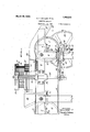
- Figure 1 is a side elevation of a portion of our piercing machine, portions of the fig are being omitted to reveal the construction and reduce the size of the'figure.
- Figure 2 is an end elevation of the main portion of our machine the direction of the view being indicated by the arrow 2 of Figure 1.
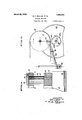
- FIG. 3 is a detailed View in elevation showing the driving cam and shaft and the related parts.
- Figure 4 is a vertical sectional view thru a portion of the head and piercing instruments. This figure is drawn to a larger scale than Figure 1.
- the machine of our invention comprises a conveyor belt adapted'to hold the objects to be pierced
- Means are provided for giving the conveyor belt a step-by-step or intermittent movement, the extent of each movement or step being substantially the same as the length of the group of piercing instruments, so that the belt carries the objects thereon below theblock of piercing instruments, pausing sufficiently between each forward movement to permit the objects then under the piercing instruments to be operated upon.
- Means are provided for reciprocating the head during these periods of rest of the conveyor beltso' that the piercing instruments are thrust into and withdrawn from the objects lying thereunder on the belt.
- Means are also provided for retaining the objects on the belt, both before and after they have been pierced, and for discharging the objects at a convenient point.
- our machine comprises i a main frame built of wood or metal and comprising the horizontal spaced and parallel rails 2, supported on the upright members 3 extending upwardly from the base 4, which may be either the floor or a low platform.
- the shafts 8 and 9 are the shafts 8 and 9, carrying the pulleys 11 and 12 respectively.
- the pulleys are each provided with a flange 13.
- brackets 17 Fixed on the frame members 3, below the shaft 8 are brackets 17, in which the bearing blocks 18 are adjustably mounted by means of the set screws 19. I
- a driving cam or drum cam 23 is fixed on'the drive shaft.
- this driving cam or drum has a cylindrical peripheral surface of two different diameters, the surface 28 constituting the active or operative face of the drum, and the surface 23? constituting the inactive face of the drum.
- the active face of the drum is formed on a radiu equal to. the distan e between the center of rotation of the drive shaft 21 and the face of the belt overlying the pulley 11, and the inactive face 23 is formed on a less radius, so that it is not in contact with the belt at any point.
- the conveyor belt 14 is given a step-by-step movement, the foward movement depending on the length of the active cam face and the length of the rest period depending on the length of the inactive cam face.
- a headblock or bracket 28 is lined at the top of each of the rods 27, and a spring 29 is interposed between each bracket 28 and the com panion bearingblock 26, to resiliently hold the bracket-s 28 and rods 27 at a predetermined height.
- a head block 31 in which are mounted a plurality of tubes 32, flush with the upper surface of the head block but extending below it into apertures 33 formed in the stripping plate 34, which is mounted between the head block and the upper reach of the conveyor belt. It is convenient to support this stripping plate upon the guide walls 36 arranged on the main frame, one on each side of the conveyor belt.
- each tube 32 Disposed in each tube 32 is a shaft 37, conveniently formed of piano wire or similar material, and having a head 38 at the upper end overlying the head block.
- These shafts 37 comprise the piercing instruments of the machine, and extend down below the ends ofthe' tubes 32 and substantially thru the stripping plate 34. The amount of the extension is of course determined by the amount of penetration desired.
- a retaining plate 39 is secured to the upper face of the head block by the bolts 41, of which there may be four. It will be obvious that With the removal of these fastening bolts, access may be had to any of the piercing instruments for cleaning, if that should be necessary, or for replacement or repair.
- the upper ends of the tubes 32 are flared outwardly as shown in Figure 4, in order to prevent the tubes from dropping thru the head block and these tubes are retained in position by the engagement of the retaining.
- the spring 29 on each side resiliently rctains the piercing head in its raised or uppermost position, and means are provided for lowering or depressing the piercing head to thrust the piercing shafts or instruments into the objects on the conveyor belt below the stripping plate.
- each lever 44 Fixed on the driving shaft 21 on each side of the driving cam is a plate cam 42, adapted in its rotation to engage the roller 43, on one end of the lever 44, mounted on the pivot pin 46, carried in the bracket 47, which is mounted on the frame member 3.
- the other end of each lever 44 lies above and. in contact with the roller 48 mounted on the lower end of each rod 27.
- Rotation of the cams 1-2 thus is effective to draw down the rod 27, and the connected head block and piercing shafts; the extent of the movement being such that at the lowermost portion of the stroke, the piercing shafts almost touch the belt, that is to say, they have passed thru the objects lying on the belt.
- the recovery movement of the head block and the piercing instruments is effected by the springs 29, as the cams 42 rotate away from the rollers 43.
- the relative positions of the cams 42 and the driving cam 23, are such that the levers 44 are actuated by the cams 42 after the active face of the driving cam has broken contact with the belt, and the movement of the piercing instruments, both operative and recovery, is completed before the active cam face 23 again engages the belt.
- the belt comes to rest for an aopreci able period before the descending piercing shafts engage the objects on the belt, and the recovery movement of the piercing shafts is complete and the stripped objects are at rest on the belt before the nexttforward movement of the belt occurs.
- the amount of forward movement of the belt each time is substantially equal to the length of the group of piercing points so that every portion of the belt is successively brought to rest below the stripping plate.
- Any'convenientmeans may be utilized for putting the objects u on the belt. They may be placed there by hand or discharged thereon from'a suitably disposed chute, the effort being made to spread the objects around on the belt in a single layer. In practiceit is found that very little attention need begiven to this phase of the operation of the machine. If a few of the objects happen to be piled more than one deep, the engagement with the rear face of the strip ping plate serves to sweep them. baokupon the belt.
- a discharge chute 51 is arranged as shown in Figure l in front of the pulley 11, the pierced objects rolling off of the belt as it rot-ates and falling thru the chute 51 into a suitable receptacle placed thereunder.
- the active face of the driving cam 23 may be slightly roughened, or faced with a nonslip material such as rubber, and its tension against the belt 14 is regulated by the adjusting screws 19.
- a piercing machine comprising a conveyor belt adapted to carry the objects to be pierced, a head arranged for vertical movement above said conveyor, a group of piercing points disposed on the underside of said head, a driving cam engaging said belt during a part of the revolution of the cam, and means operative during the period of no engagement between cam and belt for depressing said head.
- a piercing machine comprising a conveyor belt adapted to carry the objects to be pierced, a head arranged for vertical move ment above said conveyor, a group of pierc ing points disposed on the underside of said head,a driving shaft, a drum cam on said shaft in engagement with said belt during a part of the revolution of the cam, an operating lever connected to said head, and a cam on said shaft for actuating said lever to depress said head during the period of no engagement between the drum cam and belt.
- a piercing machine comprising a con- 7 before it is depressed and removing said 7 objects after its recovery movement.
- a piercing machine comprlsinga conveyorbelt adapted to carry the objects to be pierced, a head arranged for vertical movement above said conveyor, a group of pierc-' ing points disposed on the underside of said head, a stripping plate ,thru which said points operate, pulleys for carrying said belt, a drum having a stepped cylindrical surface part of which forms a'driving engagement with the portion of the belt in contact with one of said pulleys, a cam mounted for rotation with said drum and a lever actuated by said cam operatively connected to said head.
- a head block a plurality of tubes arranged in said block, a headed shaft comprising a piercing instrument disposed in each tube, and a retaining plate overlying the heads of the shafts to hold them in the tubes.
- a head block In a piercing machine, a head block, an apertured stripping plate spaced from the block, a plurality of tubes fixed in the head block and extending into the apertures of the stripping plate, a headed shaft comprising a piercing instrument disposed in each tube and extending substantially thru the stripping plate, and a retaining plate overlying the heads of the shafts to hold them in the tubes.
Landscapes
- Life Sciences & Earth Sciences (AREA)
- Chemical & Material Sciences (AREA)
- Engineering & Computer Science (AREA)
- Food Science & Technology (AREA)
- Polymers & Plastics (AREA)
- Preliminary Treatment Of Fibers (AREA)
Description
March 20, 1928. 1 ,663213 E. MULLER ET AL PIERCING MACHINE 3 Filed m 26. 1925 s Sheets-Sheetl g v rall 6 2272; 4407/;-
awlm Mmh 20, 1928.
' 1,663,213 v E. F. MULLER ET AL PIERCING MACHINE Filed Oct. 26, 1925 3 h t he t 2 March 20, 1928.
F1 GL4- 1,663,213 5. F. MULLER ET AL VPIERCING MACHINE Filesl 091;; 26. 1925 Avvawrona E/wsf' F. Mu/ler an Gar-I 6. Mu//er 9 3 Sheets-Sheet 3 Patented Mar. 29, 1928.,
FATE
ERNST F. MULLER AND CARL G. MULLER, OF OAKLAND, CALIFORNIA.
rinncrne MACHINE.
Application filed October 26, 1925. Serial No. 64,821.
Another object of the invention is the pro-v vision, in a machine of the character referred to, of piercing means which is readily disassembled for cleaning, or for the renewal of parts.
Another object of the invention is the provision of a piercing machine which does not break or tear the object operated upon and in which the piercing instrument is thrust straight into the object and withdrawn without injury.
Other objects of the invention include the provision of improved feeding means and improved means for operating the piercing instruments.
Our invention possesses other objects and features of advantage, some of which with the foregoing will be set forth in the following description of the preferred form of our invention which is illustrated in the drawings accompanying and forming part of the specification. It is to be understood that we do not limit ourselves to the showing made by the said drawings and description, as we may adapt variations of the preferred form within the scope of our inven tion as set forth in the claims.
Referring to the drawings:
Figure 1 is a side elevation of a portion of our piercing machine, portions of the fig are being omitted to reveal the construction and reduce the size of the'figure.
Figure 2 is an end elevation of the main portion of our machine the direction of the view being indicated by the arrow 2 of Figure 1.
Figure 3 is a detailed View in elevation showing the driving cam and shaft and the related parts.
Figure 4: is a vertical sectional view thru a portion of the head and piercing instruments. This figure is drawn to a larger scale than Figure 1.
In broadly descriptive terms the machine of our invention comprises a conveyor belt adapted'to hold the objects to be pierced,
and above which is arran ed for vertical" movement, a block on which is mounted a plurality of piercing instruments. Means are provided for giving the conveyor belt a step-by-step or intermittent movement, the extent of each movement or step being substantially the same as the length of the group of piercing instruments, so that the belt carries the objects thereon below theblock of piercing instruments, pausing sufficiently between each forward movement to permit the objects then under the piercing instruments to be operated upon. Means are provided for reciprocating the head during these periods of rest of the conveyor beltso' that the piercing instruments are thrust into and withdrawn from the objects lying thereunder on the belt. Means are also provided for retaining the objects on the belt, both before and after they have been pierced, and for discharging the objects at a convenient point.
More particularly our machine comprises i a main frame built of wood or metal and comprising the horizontal spaced and parallel rails 2, supported on the upright members 3 extending upwardly from the base 4, which may be either the floor or a low platform. J ournaled in the bearing blocks 6 and 7, fixed on each side of the frame, are the shafts 8 and 9, carrying the pulleys 11 and 12 respectively. Preferably the pulleys are each provided with a flange 13. A belt'l l of leather, canvas or other suitable material, passes around the-pulleys 11 and 12, and the rear bearing blocks 7 are adjusted by the set screws 16 to give the tie sired tension to the belt. v
Fixed on the frame members 3, below the shaft 8 are brackets 17, in which the bearing blocks 18 are adjustably mounted by means of the set screws 19. I
J ournaled in the bearing blocks 18 is the drive shaft 21, carrying the drive pulley 22, which is belted to any convenient line shaft or motor pulley.
Between the bearing blocks 18, a driving cam or drum cam 23 is fixed on'the drive shaft. As best shown in Figure 3, this driving cam or drum has a cylindrical peripheral surface of two different diameters, the surface 28 constituting the active or operative face of the drum, and the surface 23? constituting the inactive face of the drum. The active face of the drum is formed on a radiu equal to. the distan e between the center of rotation of the drive shaft 21 and the face of the belt overlying the pulley 11, and the inactive face 23 is formed on a less radius, so that it is not in contact with the belt at any point. hen the driving shaft is turning, rotation of the driving cam brings the active face into driving engagement with a portion of the belt 14 overlying the pulley, and causes the belt to move a distance equal to the length of the active face, the pulleys turning on their respective axes. 7
As the active face 23 of the driving cam leaves the belt, the belt stops and remains at rest until again picked up by engagement of the cam. Thus the conveyor belt 14 is given a step-by-step movement, the foward movement depending on the length of the active cam face and the length of the rest period depending on the length of the inactive cam face.
Slidably disposed for vertical movement in the bearings 26 fixed on the frame members are two rods 27, one on each side of the upper reach of the conveyor belt. A headblock or bracket 28 is lined at the top of each of the rods 27, and a spring 29 is interposed between each bracket 28 and the com panion bearingblock 26, to resiliently hold the bracket-s 28 and rods 27 at a predetermined height.
Between the brackets 28 is fixed a head block 31, in which are mounted a plurality of tubes 32, flush with the upper surface of the head block but extending below it into apertures 33 formed in the stripping plate 34, which is mounted between the head block and the upper reach of the conveyor belt. It is convenient to support this stripping plate upon the guide walls 36 arranged on the main frame, one on each side of the conveyor belt. 7 I
Disposed in each tube 32 is a shaft 37, conveniently formed of piano wire or similar material, and having a head 38 at the upper end overlying the head block. These shafts 37 comprise the piercing instruments of the machine, and extend down below the ends ofthe' tubes 32 and substantially thru the stripping plate 34. The amount of the extension is of course determined by the amount of penetration desired. In order to hold all of the piercing shafts in proper place in their respective tubes, a retaining plate 39 is secured to the upper face of the head block by the bolts 41, of which there may be four. It will be obvious that With the removal of these fastening bolts, access may be had to any of the piercing instruments for cleaning, if that should be necessary, or for replacement or repair.
The upper ends of the tubes 32 are flared outwardly as shown in Figure 4, in order to prevent the tubes from dropping thru the head block and these tubes are retained in position by the engagement of the retaining.
The spring 29 on each side resiliently rctains the piercing head in its raised or uppermost position, and means are provided for lowering or depressing the piercing head to thrust the piercing shafts or instruments into the objects on the conveyor belt below the stripping plate.
Fixed on the driving shaft 21 on each side of the driving cam is a plate cam 42, adapted in its rotation to engage the roller 43, on one end of the lever 44, mounted on the pivot pin 46, carried in the bracket 47, which is mounted on the frame member 3. The other end of each lever 44 lies above and. in contact with the roller 48 mounted on the lower end of each rod 27.
Rotation of the cams 1-2 thus is effective to draw down the rod 27, and the connected head block and piercing shafts; the extent of the movement being such that at the lowermost portion of the stroke, the piercing shafts almost touch the belt, that is to say, they have passed thru the objects lying on the belt. The recovery movement of the head block and the piercing instruments is effected by the springs 29, as the cams 42 rotate away from the rollers 43. The relative positions of the cams 42 and the driving cam 23, are such that the levers 44 are actuated by the cams 42 after the active face of the driving cam has broken contact with the belt, and the movement of the piercing instruments, both operative and recovery, is completed before the active cam face 23 again engages the belt.
Thus the belt comes to rest for an aopreci able period before the descending piercing shafts engage the objects on the belt, and the recovery movement of the piercing shafts is complete and the stripped objects are at rest on the belt before the nexttforward movement of the belt occurs. The amount of forward movement of the belt each time is substantially equal to the length of the group of piercing points so that every portion of the belt is successively brought to rest below the stripping plate. Thus all of the objects on the belt are certain to be engaged by the piercing point-s.
Any'convenientmeans may be utilized for putting the objects u on the belt. They may be placed there by hand or discharged thereon from'a suitably disposed chute, the effort being made to spread the objects around on the belt in a single layer. In practiceit is found that very little attention need begiven to this phase of the operation of the machine. If a few of the objects happen to be piled more than one deep, the engagement with the rear face of the strip ping plate serves to sweep them. baokupon the belt. A discharge chute 51 is arranged as shown in Figure l in front of the pulley 11, the pierced objects rolling off of the belt as it rot-ates and falling thru the chute 51 into a suitable receptacle placed thereunder.
The active face of the driving cam 23 may be slightly roughened, or faced with a nonslip material such as rubber, and its tension against the belt 14 is regulated by the adjusting screws 19.
lVe have found our machine exceedingly useful and eflicient in preparing cucumbers for the pickling process, large quantities of the cucumbers passing thru the machine in a continuous stream with little or no attention. The punctures formed by our machine are the size of the piercing shafts, and because the piercing shafts are thrust straight into the cucumber while it is at rest and is withdrawn before the belt again starts, there is no tendency to tear or otherwise injure the cucumber. By spacing the piercing instruments at the desired intervals, the number of punctures per unit of area, is predetermined so that during the pickling process the solutions may penetrate to the best advantage. There is thus nothing left to chance or to the judgment of the worker. This results in a superior product, and materially reduces the cost of this step in the pickling process.
We have described our machine as best suited for piercing such objects as cucumbers, but it will be obvious without special illustration or description that our invention could be embodied in other forms particularly adapted for perforating other objects.
We claim:
1. A piercing machine comprising a conveyor belt adapted to carry the objects to be pierced, a head arranged for vertical movement above said conveyor, a group of piercing points disposed on the underside of said head, a driving cam engaging said belt during a part of the revolution of the cam, and means operative during the period of no engagement between cam and belt for depressing said head.
2. A piercing machine comprising a conveyor belt adapted to carry the objects to be pierced, a head arranged for vertical move ment above said conveyor, a group of pierc ing points disposed on the underside of said head,a driving shaft, a drum cam on said shaft in engagement with said belt during a part of the revolution of the cam, an operating lever connected to said head, and a cam on said shaft for actuating said lever to depress said head during the period of no engagement between the drum cam and belt.
3. A piercing machine comprising a con- 7 before it is depressed and removing said 7 objects after its recovery movement.
4;. A piercing machine comprlsinga conveyorbelt adapted to carry the objects to be pierced, a head arranged for vertical movement above said conveyor, a group of pierc-' ing points disposed on the underside of said head, a stripping plate ,thru which said points operate, pulleys for carrying said belt, a drum having a stepped cylindrical surface part of which forms a'driving engagement with the portion of the belt in contact with one of said pulleys, a cam mounted for rotation with said drum and a lever actuated by said cam operatively connected to said head.
5. In a piercing machine, a head block, a plurality of tubes arranged in said block, a headed shaft comprising a piercing instrument disposed in each tube, and a retaining plate overlying the heads of the shafts to hold them in the tubes.
6. In a piercing machine, a head block, an apertured stripping plate spaced from the block, a plurality of tubes fixed in the head block and extending into the apertures of the stripping plate, a headed shaft comprising a piercing instrument disposed in each tube and extending substantially thru the stripping plate, and a retaining plate overlying the heads of the shafts to hold them in the tubes.
In testimony whereof, we have hereunto set our hands.
ERNST F. MULLER. CARL G. MULLER.
Priority Applications (1)
| Application Number | Priority Date | Filing Date | Title |
|---|---|---|---|
| US6482125 US1663213A (en) | 1925-10-26 | 1925-10-26 | Piercing machine |
Applications Claiming Priority (1)
| Application Number | Priority Date | Filing Date | Title |
|---|---|---|---|
| US6482125 US1663213A (en) | 1925-10-26 | 1925-10-26 | Piercing machine |
Publications (1)
| Publication Number | Publication Date |
|---|---|
| US1663213A true US1663213A (en) | 1928-03-20 |
Family
ID=22058453
Family Applications (1)
| Application Number | Title | Priority Date | Filing Date |
|---|---|---|---|
| US6482125 Expired - Lifetime US1663213A (en) | 1925-10-26 | 1925-10-26 | Piercing machine |
Country Status (1)
| Country | Link |
|---|---|
| US (1) | US1663213A (en) |
-
1925
- 1925-10-26 US US6482125 patent/US1663213A/en not_active Expired - Lifetime
Similar Documents
| Publication | Publication Date | Title |
|---|---|---|
| US2656962A (en) | Receptacle filling machine | |
| US1781546A (en) | Dough-molding machine | |
| US3172372A (en) | Method and apparatus for the rolling of materials | |
| US1835190A (en) | Machine for operating on fruits and the like | |
| US4220080A (en) | Machine for pitting and stuffing olives | |
| US3301454A (en) | Food handling apparatus | |
| US1663213A (en) | Piercing machine | |
| US3031714A (en) | Shrimp de-veiner | |
| US3434517A (en) | Automatic coring machine | |
| US2404882A (en) | Article handling apparatus | |
| US760417A (en) | Machine for separating and assembling crackers. | |
| US2595305A (en) | Rolling, stamping, and cutting machine for dough | |
| US1364083A (en) | Machine for blanching nuts | |
| US1753393A (en) | Dough-molding machine | |
| US1908771A (en) | Automatically operating discharge device for cigarette machines | |
| US2234841A (en) | Machine for slitting rolls | |
| US2143020A (en) | Peanut blanching machine | |
| US2261062A (en) | Machine for separating frangible sheet material | |
| US2179474A (en) | Fruit treating machine | |
| US2817517A (en) | Blank feeding apparatus | |
| US1865750A (en) | Machine for feeding and collecting sheets of paper or the like | |
| US1291168A (en) | Roll-stamping machine. | |
| US1970107A (en) | Feeding device | |
| US998017A (en) | Dough-treating mechanism. | |
| US1539300A (en) | Eish cutting and cleaning machine |