US1663211A - Logometer - Google Patents
Logometer Download PDFInfo
- Publication number
- US1663211A US1663211A US411502A US41150220A US1663211A US 1663211 A US1663211 A US 1663211A US 411502 A US411502 A US 411502A US 41150220 A US41150220 A US 41150220A US 1663211 A US1663211 A US 1663211A
- Authority
- US
- United States
- Prior art keywords
- shaft
- hand
- hands
- port
- starboard
- Prior art date
- Legal status (The legal status is an assumption and is not a legal conclusion. Google has not performed a legal analysis and makes no representation as to the accuracy of the status listed.)
- Expired - Lifetime
Links
Images
Classifications
-
- G—PHYSICS
- G01—MEASURING; TESTING
- G01P—MEASURING LINEAR OR ANGULAR SPEED, ACCELERATION, DECELERATION, OR SHOCK; INDICATING PRESENCE, ABSENCE, OR DIRECTION, OF MOVEMENT
- G01P3/00—Measuring linear or angular speed; Measuring differences of linear or angular speeds
- G01P3/02—Devices characterised by the use of mechanical means
- G01P3/04—Devices characterised by the use of mechanical means by comparing two speeds
Definitions
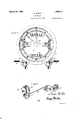
- Fig. 1 is a front elevation of the instrument
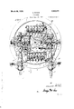
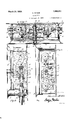
- Fig. 2 a vertical sectional view on the line II-II of Fig. 3;
- Fig. 3 a transverse horizontal sectional view taken through the center ofthe apparatus
- Fig. 4 a transverse vertical sectional view taken on the line IV--IV of Fig. 2;
- Fig. 5 a similar view on the line V-V of Fig. 2," y
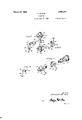
- Fig. 6 a detail perspective view of the actuating mechanism of one of the ⁇ totalizers
- Fig. 9 a perspective view of two hands (broken away) illustrative of the manner in which the are mounted; and n Fig. a etai] view of one of the .locking springs employed in connection with the clutch actuating plungers.-
- the navigatmg oicer In the navigation of a vessel of the twm screw type it is desirable that the navigatmg oicer should be able to know at a glance the direction of rotation of each propeller shaft; the R. P. M. ofthe shafts; the total number of revolutions ⁇ had; and the relative speed of rotation of one shaft to the other.
- the object of the present invention is to produce a mechanism which makes the indications just noted and readily-admits of securing the R. P. M. of each shaft, one independently of the other.
- the casing comprises a back plate 1 having an attaching flange 2, and a forwardly extending circular body or casing 3, the outer forward face of which is exteriorly threaded to receive a bezel 4 which carries a cover lass 5.
- the face plate is denoted by 6, and is provided with openings through which the various counters, see Fig. 1, are visible.
- the mechanism lem- 60 bodies a total and a hundredscounter or indicator for the starboard shaft and a similar palr f counters for the port shaft, and inasmuch as most of the actuating .parts are duplicated for each set of counters, the starboard elements will be described and the corresponding parts for the port shaft will be similarly numbered with a rime added thereto.
- Attached to the lliiwer portion of the casing 3 is a U-shaped bracket 6 in the -lower element of which is journaled a rotatable element 7 connected by any suitable means to the starboard propeller shaft and partaking of the motions thereof.
- Said element has secured to it a clutch element 8 which cooperates with a shiftable clutch element 9 slidably mounted on the squared end of a stub-shaft 10 journaled in the bracket.
- a shifting lever 11 is provided to hold thel movable clutch in its locked or released position.
- Shaft 10 - is jointed to a shaft 12 70 located in alinement therewith and su ported in suitable bearings 13 and 14, sald shaft having secured thereto a bevel gear 15 which meshes with a similar gear 16.
- Gear 16 is secured to one end of a shaft 17 75 journaled in a bearing 18, the shaft at its opposite end carrying a wrist plate 19 to the pin of which is attached a pitman 20.
- the shaft adjacent its outer end is provided with a cross pin 38 which'passes into a relatively deep cross notch 39 formed in the hub 40 of hand 28 and inasmuch as said pin is always in the slot or notch the hand will partake of any movement imparted to the shaft.
- the outer end of the shaft is interiorly threaded and a screw-like member 41 is attached thereto, the head of the screw overlying the outer end of the hub 40 of the hand 28, and preventing outward movement of said hub.
- a socket-ed finger-piece or knob 42 is secured to the outer portion of hub 40, and a spring 43 is seated within the knob and bears against the head of screw 41.
- the hand 28 and its hub 40 may be moved inwardly to a slight extent so that a pin 44 carried by the hand may be passed into an opening 45 formed in the hand 28', thus locking the hands together and permitting them to be turned manually to any desired point on the dial or face 6, the ob]ect of which will presently appear.
- Hand 28 is secured to the outer end of sleeve 31, the sleeve having mounted thereon a fixed collar 46 and a spring pressed friction element 47, which cooperates with the huh of vthe worin wheel 34.
- Mo tion is imparted to each of said worin wheels 34 and 34 and consequently to the hands 28 and 28 through the following mechanism which also actuates the hundreds indicating wheels, starboard and port, the mechanism being duplicated so that a description of one will suffice, the numerals of like parts of the second mechanism being similarly numbered and primed.
- Said coned extensionY cooperates with a clutch element 51 which is slidably mounted on a squared section 52 of shaft 12, said element being normally pressed toward the cooperating cone element by a spring 53, the opposite end of which bears against a washer 54 pinned to the shaft.
- gear 48 rotates with shaft 12.
- the clutch element is provided with an annular groove 55 into which take the ngers 56 of a yoke 57, the latter forming one arm of an elbow lever fulerumed. upon a screw 58, the other arm standing vertical and denoted by 59.
- Gear 48 meshes with an idler 66 which in turn meshes with a gear 67 secured upon a shaft 68 mounted in bearings 69 and 70 formed upon a bracket member 71. Said member is also formed with an arm 72 in the outer end of which the bearing 32, heretofore referred to,fis made. Shaft 68 has secured to it a worm 73 which meshes with worm wheel 34 and imparts motion thereto and consequently to hand 28. The same arrangement is duplicated for the port side of the mechanism, the worm gear 34 imparting movement through sleeve 31 to the port hand 28.
- a hundreds indicator wheel 74 is arranged to be moved in consonance with the starboard hand and a similar wheel 74 is likewise provided on the port side. of the meter, said wheels being mounted and operated in a similar manner, as will now he, described.
- Wheel 74 is pinned to a shaft 75, the inner end whereof is supported in a bearing 76 while the opposite end passes outwardly of the casing through a bearing 77, the outer end of the shaft being knurled to provide a finger hold.
- Shaft 80 has secured to its opposite end a lever 82, the lower end of which is forked and into which extends a linger 83 protruding from the end of a lever 84 fulcrumed upon a stud 85 extending outwardly from the bracket member or plate 71, see Fig. 2.
- Said lever 84 carries a roll 86 which stands above the friction element 36, said element being formed with a lifter cam 87, said caln raising the lever once for each revolution of shaft 29 and .consequently advancing the hundreds wheel or indicator 74 one step through the actuation of the mechanism just described.
- the port hundreds wheel or indicator 74 is actuated in a like manner and throughsimilar mechanism, but inasmuch as its lever 84 underlies the friction element 47 the lever is fulcrumed intermediate its ends upon a shaft 88 mounted in the bracket arm 72, see Fig. 2. Furthermore, the roller 86 is mounted adjacent-the inner end of the lever and a weight 89 is secured to the opposite end thereby ensuring the roller being held yagainstthe friction element 47 and the actuating cam 87.
- the face plate 6 will be provided with suitable openings in registry with the various counter or register elements and adjacent the periphery thereof will be graduated from 0 to 100. Suitable legends, as Ahead and Astern, together with indication arrows, will preferably be provided, so that one viewing the same may see at a glance in which direction the propeller shafts are rotating.
- the instrument when installed on the bridge of a vessel is of the greatest assistance to the navigator.
- thel engineer When installed in the engine room thel engineer can note instantly the actual respective speeds of the port and starboard units and is thus ⁇ enabled to synchronize the speeds exactly.
- the instrument also shows at a glance the direction of rotation of each propeller shaft, allows the R. P. M. of either shaft to be taken at will, and registers separately the total number of revolutions of each shaft.
- the instrument furnishes data-which may be of assistance to the navigating @meer as to:
- the hundreds counter wheel of the stai'- board engine will be likewise arrested. rIhe hand is then turned back to zero, through the manipulation of the finger-piece 42 and the hundreds wheel is likewise turned back to zero by rotating the shaft 75, the outer knurled end thereof facilitating this operation.
- the knob 65 is then pushed inwardly causing reengagement of the clutch element with the gear 48 and the parts are continued to operate for a period of a minute when the clutch is again released.
- the R. P. M. is then ascertained by reading the registration on the hundreds counter plus the number of revolutions indicated by the hand 28. When it is desired to secure the simultaneous R. P. M. of both the starboard and port propeller shafts both of the clutch elements are released and both of the hundreds wheels are returned to zero.
- the operator also pushes the knob 42 inwardly having rotated the hand 28 so as tobring the pin 44 into alinement with the opening 45 in the hand 28 thereby causing the two hands to move as one, and then rotates the knob so that both hands are brought to zero.
- the knob is then released and the clutches simultaneously caused to engage by an inward movement of the knobs 65 and 65.
- the rotation is permitted for the period of av minute, when both clutches are again simultaneously released.
- the totalizing registers operate continuously, that is to say, they register whether the engine shafts are rotated either ahead or astern.
- the shafts 7 and 7 are disconnected by the manipulation of the hand levers 11 and 11, the instrument is brought to rest, which, of course, is advantageous when the engines are being tuned up, or for charging storage batteries or the like, at which time the Vessel is usually not under headway.
- the combination with two hands independently rotatable about the same axis, of hand setting means including amember rotatable about said axis and movable along saidY axis to one position for locking said hands together, when brought into coincidence, to permit both hands to be turned together to a. desired position, the hands being unlocked from each other by restoration of the handle to its original position along said axis.
- a front hand and a rear hand rotatable aboutthe same axis, spring means normally holding said front hand in a forward position, means for setting said hands to a desired position comprising interengaging means on said hands to connect the same together when the hands are in sub stantial coincidence and the front hand is pressed rearwardly.
- the combination with tWo hands .independ- 5 ently rotatable about the same axis, of means for setting said hands to a desired position comprising means on said hands adapted for mutual engagement to connect said hands preliminary to setting the same, means normally pressing the hands apart, and manlually operable means for effecting such muname to this specification.
Landscapes
- Physics & Mathematics (AREA)
- General Physics & Mathematics (AREA)
- Mechanical Operated Clutches (AREA)
Description
March 20, 1928. 1,663,211
A. MCNAB LOGOMETER Filed Sept. 20, 192D 4 Sheets-Sheet 1 March 20, 1928. 1,663,211
Y A. McNAB LOGOMETER Filed septfzo. 1920 4 sheets-sheet 2 4 Sheets-Sheet 3 A. McNAB LOGOMETER Filed Sept. 20, 1920 Y 1 x 28 78 i 594/VY March 20, 1928.
3141x2111 oz lill lrotneq( March 20, 1928. 1,663,211 n A. MCNAB LOGOMETER Filed Sept. 20, 1920 4 Sheets-S1169!l 4 Patented Mar. 20, 1928.
UNITED STATES PATENT OFFICE.
LOGOHETER.
Application led September 20, 1920. Serial No. 411,502.
My present invention pertains to logometers, the construction and advanta es of which will be hereinafter set forth, re erence being had to the annexed drawings, whereinf Fig. 1 is a front elevation of the instrument;
Fig. 2 a vertical sectional view on the line II-II of Fig. 3;
Fig. 3 a transverse horizontal sectional view taken through the center ofthe apparatus;
Fig. 4 a transverse vertical sectional view taken on the line IV--IV of Fig. 2;
Fig. 5 a similar view on the line V-V of Fig. 2," y
Fig. 6 a detail perspective view of the actuating mechanism of one of the` totalizers;
Figs. 7 and 8 similar View of the actuating devices of the hundreds counters;
Fig. 9 a perspective view of two hands (broken away) illustrative of the manner in which the are mounted; and n Fig. a etai] view of one of the .locking springs employed in connection with the clutch actuating plungers.-
In the navigation of a vessel of the twm screw type it is desirable that the navigatmg oicer should be able to know at a glance the direction of rotation of each propeller shaft; the R. P. M. ofthe shafts; the total number of revolutions` had; and the relative speed of rotation of one shaft to the other.
The object of the present invention is to produce a mechanism which makes the indications just noted and readily-admits of securing the R. P. M. of each shaft, one independently of the other.
Such a structure is disclosed in the drawings, wherein the casing comprises a back plate 1 having an attaching flange 2, and a forwardly extending circular body or casing 3, the outer forward face of which is exteriorly threaded to receive a bezel 4 which carries a cover lass 5. The face plate is denoted by 6, and is provided with openings through which the various counters, see Fig. 1, are visible. The mechanism lem- 60 bodies a total and a hundredscounter or indicator for the starboard shaft and a similar palr f counters for the port shaft, and inasmuch as most of the actuating .parts are duplicated for each set of counters, the starboard elements will be described and the corresponding parts for the port shaft will be similarly numbered with a rime added thereto. Attached to the lliiwer portion of the casing 3 is a U-shaped bracket 6 in the -lower element of which is journaled a rotatable element 7 connected by any suitable means to the starboard propeller shaft and partaking of the motions thereof. Said element has secured to it a clutch element 8 which cooperates with a shiftable clutch element 9 slidably mounted on the squared end of a stub-shaft 10 journaled in the bracket. A shifting lever 11 is provided to hold thel movable clutch in its locked or released position. Shaft 10 -is jointed to a shaft 12 70 located in alinement therewith and su ported in suitable bearings 13 and 14, sald shaft having secured thereto a bevel gear 15 which meshes with a similar gear 16. Gear 16 is secured to one end of a shaft 17 75 journaled in a bearing 18, the shaft at its opposite end carrying a wrist plate 19 to the pin of which is attached a pitman 20. Said pitman at its upper end 1s pivotally connected to one end of an arm or lever 21, the 8o opposite end of which is secured to thesupporting shaft 22 of an anchor, or an oscillating actuator 23. `Said anchor cooperates with a ratchet wheel 24 which in turn actuates the mechanism of the total revolution counter, denoted generally b 25, which may be of any suitable or stan ard type. The actuation of the total counter for the port shaft takes place in the same manner but in view of the fact that the gearing 15 90 and 16 is located to the left of the counter the construction shown in Fig, 6 is employed, wherein an extended shaft 26 and a craink 2,7 are employed; see also Figs. 2 an `5.
From the foregoing it will be seen that each and every revolution of both the port and starboard shafts will be registered so lohg as the clutches remain locked. To visually indicate the direction of movement 10 of the shafts two hands or pointers 28 and `28 are employed. Said hands are driven through means, about to be described, in consonance with the .movements of the respective starboard and port shafts and are mounted in the manner best Shown in Figs. 3 and 9. A shaft 29 is mounted at its inner end in a fixed bearing 30 the shaft adjacent its forward end being supported in a sleeve 31 which latter is journaled in a fixed bearing 32. The shaft passes through the face plate 6 and through an opening 33 formed in the cover glass 5. A worm wheel 34 is journaled on the shaft intermediate a. collar 35 fixed to the shaft and a cone shaped friction member 36 which makes a friotional connection with the hub of the wheel through the action of a spring 37. The shaft adjacent its outer end is provided with a cross pin 38 which'passes into a relatively deep cross notch 39 formed in the hub 40 of hand 28 and inasmuch as said pin is always in the slot or notch the hand will partake of any movement imparted to the shaft. The outer end of the shaft is interiorly threaded and a screw-like member 41 is attached thereto, the head of the screw overlying the outer end of the hub 40 of the hand 28, and preventing outward movement of said hub. A socket-ed finger-piece or knob 42 is secured to the outer portion of hub 40, and a spring 43 is seated within the knob and bears against the head of screw 41. By this arrangement the hand 28 and its hub 40 may be moved inwardly to a slight extent so that a pin 44 carried by the hand may be passed into an opening 45 formed in the hand 28', thus locking the hands together and permitting them to be turned manually to any desired point on the dial or face 6, the ob]ect of which will presently appear. Hand 28 is secured to the outer end of sleeve 31, the sleeve having mounted thereon a fixed collar 46 and a spring pressed friction element 47, which cooperates with the huh of vthe worin wheel 34. Mo tion is imparted to each of said worin wheels 34 and 34 and consequently to the hands 28 and 28 through the following mechanism which also actuates the hundreds indicating wheels, starboard and port, the mechanism being duplicated so that a description of one will suffice, the numerals of like parts of the second mechanism being similarly numbered and primed. Journaled on shaft 12, see Fig. 4, above bearing 13, is a gear 48, said gear being formed with a coned hub extension 49, the gear being held against longtiudinal motion on the shaft by a washer 50 let into the upper end of the cone and pinned to the shaft. Said coned extensionY cooperates with a clutch element 51 which is slidably mounted on a squared section 52 of shaft 12, said element being normally pressed toward the cooperating cone element by a spring 53, the opposite end of which bears against a washer 54 pinned to the shaft. Thus when the clutch elements vare in contact, gear 48 rotates with shaft 12. The clutch element is provided with an annular groove 55 into which take the ngers 56 of a yoke 57, the latter forming one arm of an elbow lever fulerumed. upon a screw 58, the other arm standing vertical and denoted by 59. The
upper end of said arm, see Fig. 3, is bifur- 12; when it is pulled out the clutch ele-v ments are separated and the gear comes to rest, the locking detent 62 cooperating with head 61 to hold the parts in one or the other position.
A hundreds indicator wheel 74 is arranged to be moved in consonance with the starboard hand and a similar wheel 74 is likewise provided on the port side. of the meter, said wheels being mounted and operated in a similar manner, as will now he, described.
The face plate 6 will be provided with suitable openings in registry with the various counter or register elements and adjacent the periphery thereof will be graduated from 0 to 100. Suitable legends, as Ahead and Astern, together with indication arrows, will preferably be provided, so that one viewing the same may see at a glance in which direction the propeller shafts are rotating.
The instrument, as above set forth, when installed on the bridge of a vessel is of the greatest assistance to the navigator. When installed in the engine room thel engineer can note instantly the actual respective speeds of the port and starboard units and is thus `enabled to synchronize the speeds exactly.
The instrument also shows at a glance the direction of rotation of each propeller shaft, allows the R. P. M. of either shaft to be taken at will, and registers separately the total number of revolutions of each shaft. In other words, the instrument furnishes data-which may be of assistance to the navigating @meer as to:
lst. Direction ahead and astern of port and starboard propeller shafts.
2nd. Difference in propeller shaft speed of port and starboard engines (determined mentally from instrument readings).
3rd. Speed of port and starboard propeller shafts up to 1000 R. P. M. (determined mentally in connection with the use of timing means).
4th.v Registers the total number of revolutions the port and starboard shafts have made from zero to one million; when the total is arrived at the register, as shown, repeats. It is to be understood, of course, that registers of larger capacity may be employed.
In order to ascertain the R. P. M. say of the starboard engine, the clutch knob 65 at the right hand side of the case is pulled out, thereby releasing the clutch element 51 and consequently arresting the train of gears 48,
66 and 67, and likewise arresting the movement of the shaft which carries the hand 28.-
The hundreds counter wheel of the stai'- board engine will be likewise arrested. rIhe hand is then turned back to zero, through the manipulation of the finger-piece 42 and the hundreds wheel is likewise turned back to zero by rotating the shaft 75, the outer knurled end thereof facilitating this operation. The knob 65 is then pushed inwardly causing reengagement of the clutch element with the gear 48 and the parts are continued to operate for a period of a minute when the clutch is again released. The R. P. M. is then ascertained by reading the registration on the hundreds counter plus the number of revolutions indicated by the hand 28. When it is desired to secure the simultaneous R. P. M. of both the starboard and port propeller shafts both of the clutch elements are released and both of the hundreds wheels are returned to zero. The operator also pushes the knob 42 inwardly having rotated the hand 28 so as tobring the pin 44 into alinement with the opening 45 in the hand 28 thereby causing the two hands to move as one, and then rotates the knob so that both hands are brought to zero. The knob is then released and the clutches simultaneously caused to engage by an inward movement of the knobs 65 and 65. The rotation is permitted for the period of av minute, when both clutches are again simultaneously released.
It is to 'be noted that the totalizing registers operate continuously, that is to say, they register whether the engine shafts are rotated either ahead or astern. When, however, the shafts 7 and 7 are disconnected by the manipulation of the hand levers 11 and 11, the instrument is brought to rest, which, of course, is advantageous when the engines are being tuned up, or for charging storage batteries or the like, at which time the Vessel is usually not under headway.
What is claimed is,-
1. In a device of the character described, the combination with two hands independently rotatable about the same axis, of hand setting means including amember rotatable about said axis and movable along saidY axis to one position for locking said hands together, when brought into coincidence, to permit both hands to be turned together to a. desired position, the hands being unlocked from each other by restoration of the handle to its original position along said axis.
2. In a device of the character described, the combination of a front hand and a rear hand rotatable aboutthe same axis, spring means normally holding said front hand in a forward position, means for setting said hands to a desired position comprising interengaging means on said hands to connect the same together when the hands are in sub stantial coincidence and the front hand is pressed rearwardly.
3. In a device of the character described, the combination with tWo hands .independ- 5 ently rotatable about the same axis, of means for setting said hands to a desired position comprising means on said hands adapted for mutual engagement to connect said hands preliminary to setting the same, means normally pressing the hands apart, and manlually operable means for effecting such muname to this specification.
ALEXANDER MCNAB.
Priority Applications (1)
| Application Number | Priority Date | Filing Date | Title |
|---|---|---|---|
| US411502A US1663211A (en) | 1920-09-20 | 1920-09-20 | Logometer |
Applications Claiming Priority (1)
| Application Number | Priority Date | Filing Date | Title |
|---|---|---|---|
| US411502A US1663211A (en) | 1920-09-20 | 1920-09-20 | Logometer |
Publications (1)
| Publication Number | Publication Date |
|---|---|
| US1663211A true US1663211A (en) | 1928-03-20 |
Family
ID=23629196
Family Applications (1)
| Application Number | Title | Priority Date | Filing Date |
|---|---|---|---|
| US411502A Expired - Lifetime US1663211A (en) | 1920-09-20 | 1920-09-20 | Logometer |
Country Status (1)
| Country | Link |
|---|---|
| US (1) | US1663211A (en) |
Cited By (2)
| Publication number | Priority date | Publication date | Assignee | Title |
|---|---|---|---|---|
| US2476625A (en) * | 1933-11-18 | 1949-07-19 | Societty Said La Prec Moderne | Sighting apparatus for ascertaining the velocity and direction of movement of aerial targets |
| US3143290A (en) * | 1960-04-21 | 1964-08-04 | Hydroforce Ltd | Rotary converter |
-
1920
- 1920-09-20 US US411502A patent/US1663211A/en not_active Expired - Lifetime
Cited By (2)
| Publication number | Priority date | Publication date | Assignee | Title |
|---|---|---|---|---|
| US2476625A (en) * | 1933-11-18 | 1949-07-19 | Societty Said La Prec Moderne | Sighting apparatus for ascertaining the velocity and direction of movement of aerial targets |
| US3143290A (en) * | 1960-04-21 | 1964-08-04 | Hydroforce Ltd | Rotary converter |
Similar Documents
| Publication | Publication Date | Title |
|---|---|---|
| US2112704A (en) | Arrangement of instrument dials | |
| US1663211A (en) | Logometer | |
| US1617310A (en) | Repeater compass | |
| US1948946A (en) | Combined odometer and oiling indicator | |
| US2294165A (en) | Distance indicator | |
| US2324560A (en) | Navigational timepiece and setting mechanism | |
| USRE19079E (en) | Altimeter | |
| US1046633A (en) | Resetting device. | |
| US2384507A (en) | Observation instrument | |
| US2051502A (en) | Measuring instrument | |
| US1731846A (en) | besj available copx | |
| US2972813A (en) | Flight time computer | |
| US1247508A (en) | Automatic distance-indicator for ships. | |
| US3231187A (en) | Sport car rally computer | |
| US1356505A (en) | System of gunfire control | |
| US2594406A (en) | Attitude indicating unit | |
| US1072587A (en) | Speedometer. | |
| US1128695A (en) | Speed-indicator. | |
| USRE20948E (en) | Qock reading altimeter | |
| US1040345A (en) | Combined road-map and odometer. | |
| US1138653A (en) | Speedometer and tire-meter. | |
| US1223039A (en) | Revolution-counter. | |
| US825295A (en) | Speedometer. | |
| US1019007A (en) | Distance and speed meter. | |
| US378836A (en) | Speed-indicator |