US1663209A - Heat interchanger - Google Patents
Heat interchanger Download PDFInfo
- Publication number
- US1663209A US1663209A US196188A US19618827A US1663209A US 1663209 A US1663209 A US 1663209A US 196188 A US196188 A US 196188A US 19618827 A US19618827 A US 19618827A US 1663209 A US1663209 A US 1663209A
- Authority
- US
- United States
- Prior art keywords
- shell
- tube sheet
- heat interchanger
- heat
- flange
- Prior art date
- Legal status (The legal status is an assumption and is not a legal conclusion. Google has not performed a legal analysis and makes no representation as to the accuracy of the status listed.)
- Expired - Lifetime
Links
- 239000012267 brine Substances 0.000 description 5
- HPALAKNZSZLMCH-UHFFFAOYSA-M sodium;chloride;hydrate Chemical compound O.[Na+].[Cl-] HPALAKNZSZLMCH-UHFFFAOYSA-M 0.000 description 5
- 239000002184 metal Substances 0.000 description 3
- 239000003507 refrigerant Substances 0.000 description 3
- QGZKDVFQNNGYKY-UHFFFAOYSA-N Ammonia Chemical compound N QGZKDVFQNNGYKY-UHFFFAOYSA-N 0.000 description 2
- 238000005192 partition Methods 0.000 description 2
- 238000003466 welding Methods 0.000 description 2
- 229910021529 ammonia Inorganic materials 0.000 description 1
- 238000010276 construction Methods 0.000 description 1
- 230000008602 contraction Effects 0.000 description 1
- 238000001816 cooling Methods 0.000 description 1
- 230000006866 deterioration Effects 0.000 description 1
- 230000000694 effects Effects 0.000 description 1
- 230000003628 erosive effect Effects 0.000 description 1
- 239000007788 liquid Substances 0.000 description 1
- 238000000034 method Methods 0.000 description 1
- 238000012856 packing Methods 0.000 description 1
Images
Classifications
-
- F—MECHANICAL ENGINEERING; LIGHTING; HEATING; WEAPONS; BLASTING
- F22—STEAM GENERATION
- F22G—SUPERHEATING OF STEAM
- F22G3/00—Steam superheaters characterised by constructional features; Details or component parts thereof
- F22G3/009—Connecting or sealing of superheater or reheater tubes with collectors or distributors
Definitions
- EDWARD B MCCABE, OF CARBOND'ALE, PENNSYLVANIA, f.ASSIG'NOR TO CARBONDALE MACHINE COMPANY, OF CARBONDALE, PENNSYLVANIA, A CORPORATION OF PENN- SYLVANIA.
- This invention relates to heat interchangers ef the multiple tube type in which arallel j tubes are supported by a tube sheet fbrming an end wall or a transverse partition in a l 6 shell.
- the invention relates more particularly to the means employed for securing the tube sheet to the shell.
- a heat interchanger having a tube sheet provided with a groove in the inner surface thereof to form a short cylindrical aiY lill) l flange and a shell of substantially the same internal and elxternal diameters as said flange, and butt-Welded thereto.
- a heat interchanger including a tube sheet, a plurality of tubes supported thereby, and a shell' encircling said tubes, said tube sheet having a portion of one surface out away to leave a cylindrical ange upon one face thereof, and of substantially the same internal and external diameters as said shell,
Landscapes
- Engineering & Computer Science (AREA)
- Mechanical Engineering (AREA)
- General Engineering & Computer Science (AREA)
- Heat-Exchange Devices With Radiators And Conduit Assemblies (AREA)
Description
Marh 20, 1.928. 1,663,209
A E. B. MccABE HEAT INTERCHANGER Filed June 5. 192'?" Inventor y[dn/draf i1/#Mue by /3 ttornevs Patented Mar. 20, 1928.v
UNITED SA'IATIEIS PATENT OFFICE.
EDWARD B. MCCABE, OF CARBOND'ALE, PENNSYLVANIA, f.ASSIG'NOR TO CARBONDALE MACHINE COMPANY, OF CARBONDALE, PENNSYLVANIA, A CORPORATION OF PENN- SYLVANIA.
Application led June 3,
This invention relates to heat interchangers ef the multiple tube type in which arallel j tubes are supported by a tube sheet fbrming an end wall or a transverse partition in a l 6 shell. The invention relates more particularly to the means employed for securing the tube sheet to the shell.
If these parts be detachably secured and a picking is relied upon to effect a liquid- 10 tig t joint, a leak often occurs due to expansion, contraction and erosion of the metal parts and the deterioration of the packing. Various attempts have been made to electrically weld the end of the shell to the face of the tube sheet, but it is diicult to secure a ierfect joint. I have discovered that this di culty is in part due to the fact. that the tube sheet is usually of very much thicker metal than is the shell, and the thinner shell is liable to burn from the high heat whereas the thicker section radiates `or conducts away the heat and does not becomeheated to the proper temperature.
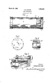
In carrying out my invention I secure a y perfect weld as well as smooth inner and outer surfaces at the welded joint by cutting a groove in the inner face of the tube sheet so as to leave a ridge or flange 'ofthe same thickness as the wall of the shell,fand of the same internal and external diameters as the latter. In this way two tubular portions of the same thickness of metal are brought into abutting engagement, and a perfect electrif cally welded joint may be produced. In the accompanying drawings I have il- 'n lustrat-ed merely one form of heat interchanger to which my invention lmay be applied. yIn these drawings: Fig. 1 is a side elevation.
Fig. 2 is an end view. Fig. 3 is a section similar toa portion of Fig. 1, but on a very much lar er scale, and Fig. 4 is a lsection of a slig tly modified form. I have illustrated my invention as applied to a heat interchanger adapted for the cooling of brine by ammonia or other liqueable gaseous refrigerant. The heat interchanger or cooler includes a tubular shell 10, a pair of tube sheets 11, and a plurality of parallel brine tubes 12. The latter are supported in the tube sheet and extend into chambers or compartments 13 at the ends.
HEAT INTEBCHANGEE.
1927. Serial No. 196,188.
" tube sheet may be detachably connected by means of bolts 16 and the chamber 13 may be divided into compartments by partitions 17 whereby liquid may enter one through an opening 18, thence lengthwise of the coolers through certain of the tubes and back through the others. The partitions maybe 05 located to divide the tubes into groups and form a zigzag path for the brine from the brine inlet 18 to a brine outlet 19. The liquefied refrigerant may be delivered to the chamber' between the tube sheets and within the shell, for instance'through 'a pipe connection 20, and thev gasi-ied refrigerant may be withdrawn from any point at the top, for instance a pipe connection 21.
The heat interchanger above described is merely one'toiwhich I may 'apply my invention. In applying the invention I cut into the tube sheet 11 an annular groove 22, and if necessary cut away the outerA portion so as to leave a short cylindrical. flange 23 of the same internal and external diameters as the shell 10. By reason ofthe fact that the flange is of the same thickness as the shell smooth surfaces are produced both on the inside and onthe outside, and the rate of heat conduction from the joint during the welding operation is substantially equal in opposite directions. Y l
Although in Fig. 1l the interchanger' is shown in a horizontal position, it will be evident that ythe invention is equally ap-l plicable to a vertical type'of device, and that the compartments and specific form of heads are not essential. In Fig. 4 I have shown a construction in vwhich the tube sheet 11'L has an voutside diameter equal to :that of the Vtube sheet 10. Therefore it is not necessary to\cut away any of theA outer portion, but only to out the groove v22 in order to form the flange. A
Having thus described my invention, what I claim as newtand desire to secure by Letters Patent is :--4
1. A heat interchanger having a tube sheet provided with a groove in the inner surface thereof to form a short cylindrical aiY lill) l flange and a shell of substantially the same internal and elxternal diameters as said flange, and butt-Welded thereto.
2. A heat interchanger including a tube sheet, a plurality of tubes supported thereby, and a shell' encircling said tubes, said tube sheet having a portion of one surface out away to leave a cylindrical ange upon one face thereof, and of substantially the same internal and external diameters as said shell,
said'fiange and said shell being electrically Welded together. l,
amazon 3. process of making heat interchangers, which includes the steps of cutting an annular groove in one face of a tube sheet so as to leave a cylindrical flange of sub-A stantially the same internal and external diameters as that of the shell, and electrically welding the end of the shell to the end of the flange.
Signed at Carbondale, in the county of l'iackawanna and State of Pennsylvania, this first day of June, A. D. 1927.
EDWARD B. MCCABE.
Priority Applications (1)
| Application Number | Priority Date | Filing Date | Title |
|---|---|---|---|
| US196188A US1663209A (en) | 1927-06-03 | 1927-06-03 | Heat interchanger |
Applications Claiming Priority (1)
| Application Number | Priority Date | Filing Date | Title |
|---|---|---|---|
| US196188A US1663209A (en) | 1927-06-03 | 1927-06-03 | Heat interchanger |
Publications (1)
| Publication Number | Publication Date |
|---|---|
| US1663209A true US1663209A (en) | 1928-03-20 |
Family
ID=22724386
Family Applications (1)
| Application Number | Title | Priority Date | Filing Date |
|---|---|---|---|
| US196188A Expired - Lifetime US1663209A (en) | 1927-06-03 | 1927-06-03 | Heat interchanger |
Country Status (1)
| Country | Link |
|---|---|
| US (1) | US1663209A (en) |
Cited By (1)
| Publication number | Priority date | Publication date | Assignee | Title |
|---|---|---|---|---|
| US2596233A (en) * | 1946-04-06 | 1952-05-13 | Bell & Gossett Co | Pressure vessel |
-
1927
- 1927-06-03 US US196188A patent/US1663209A/en not_active Expired - Lifetime
Cited By (1)
| Publication number | Priority date | Publication date | Assignee | Title |
|---|---|---|---|---|
| US2596233A (en) * | 1946-04-06 | 1952-05-13 | Bell & Gossett Co | Pressure vessel |
Similar Documents
| Publication | Publication Date | Title |
|---|---|---|
| US2151540A (en) | Heat exchanger and method of making same | |
| US3018547A (en) | Method of making a pressure-tight mechanical joint for operation at elevated temperatures | |
| US2446481A (en) | Reducing flange | |
| US2807445A (en) | Heat exchanger welded tube joint | |
| BR102016017645A2 (en) | counterflow heat exchanger that defines a centerline | |
| US2280150A (en) | Heating of metals | |
| US2969956A (en) | Pipe joint for heat exchange devices | |
| US1862310A (en) | Heat exchanger | |
| US1663209A (en) | Heat interchanger | |
| US2295522A (en) | Blowpipe head | |
| US4448245A (en) | Radiator | |
| US2145937A (en) | Welding and welded joint | |
| US2428066A (en) | Exhaust heat exchanger | |
| KR102323398B1 (en) | Welded construction of the inlet and outlet pipes of the heat exchanger | |
| US1777356A (en) | Heat-interchange apparatus | |
| US2291985A (en) | Finned tube and method of producing the same | |
| US2451587A (en) | Pipe end and joint | |
| US2396522A (en) | Radiator tube construction | |
| JP6150380B2 (en) | HEAT EXCHANGER AND HEAT EXCHANGER MANUFACTURING METHOD | |
| US2385107A (en) | Blowpipe | |
| US1886645A (en) | Heating device | |
| US2449840A (en) | Apparatus for manufacturing finned tubes | |
| US1720912A (en) | Heat interchanger | |
| US2029437A (en) | Heat conducting tube | |
| JPS6246113A (en) | Assembly for pulsating combustion |