US1663196A - Door-operating mechanism - Google Patents
Door-operating mechanism Download PDFInfo
- Publication number
- US1663196A US1663196A US184322A US18432227A US1663196A US 1663196 A US1663196 A US 1663196A US 184322 A US184322 A US 184322A US 18432227 A US18432227 A US 18432227A US 1663196 A US1663196 A US 1663196A
- Authority
- US
- United States
- Prior art keywords
- door
- cable
- lever
- arm
- housing
- Prior art date
- Legal status (The legal status is an assumption and is not a legal conclusion. Google has not performed a legal analysis and makes no representation as to the accuracy of the status listed.)
- Expired - Lifetime
Links
- 241000282596 Hylobatidae Species 0.000 description 1
- 235000018734 Sambucus australis Nutrition 0.000 description 1
- 244000180577 Sambucus australis Species 0.000 description 1
- 238000010276 construction Methods 0.000 description 1
- OYFJQPXVCSSHAI-QFPUQLAESA-N enalapril maleate Chemical compound OC(=O)\C=C/C(O)=O.C([C@@H](C(=O)OCC)N[C@@H](C)C(=O)N1[C@@H](CCC1)C(O)=O)CC1=CC=CC=C1 OYFJQPXVCSSHAI-QFPUQLAESA-N 0.000 description 1
- 239000002184 metal Substances 0.000 description 1
- 230000035939 shock Effects 0.000 description 1
Images
Classifications
-
- E—FIXED CONSTRUCTIONS
- E05—LOCKS; KEYS; WINDOW OR DOOR FITTINGS; SAFES
- E05F—DEVICES FOR MOVING WINGS INTO OPEN OR CLOSED POSITION; CHECKS FOR WINGS; WING FITTINGS NOT OTHERWISE PROVIDED FOR, CONCERNED WITH THE FUNCTIONING OF THE WING
- E05F11/00—Man-operated mechanisms for operating wings, including those which also operate the fastening
- E05F11/02—Man-operated mechanisms for operating wings, including those which also operate the fastening for wings in general, e.g. fanlights
- E05F11/04—Man-operated mechanisms for operating wings, including those which also operate the fastening for wings in general, e.g. fanlights with cords, chains or cables
Definitions
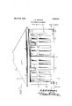
- Figure 1' is a front elevation of a garage having a door constructed in accordance with my invention
- Figure 2 is a vertical longitudinal sectional view on the line 22 of Fig. 1;
- Figure 3 is a section on the line 3+3 of Fig. 1;
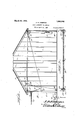
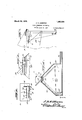
- Figure 4 is a vertical sectional view through the door operating mechanism
- Figure 5 is a top plan View of the construction shown in Figure 4.
- Figure 6 is a fragmentary elevation of the upper portion of the casing having the operating mechanism
- Figure 7 is an elevation showing the mannor in which the operating cables may be trained on the exterior of the garage.
- the garage which is designated A is provided with a door opening B defined by the jambs 6.
- each door is supported upon a transversely ext-ending rod or shaft 12 which-is shown as connected at intervals to the upper margin of the door by brackets 13 and this rod isv formedwith the crank arms 14 which are this invention is to also connected with 'the doors so thatwhen this shaft or rod is oscillated in one direction the door willbe raised, and when oscillated in the other direction, the door will be lowered, Inasmuch as-the opening mechaon V nism for both'doorsis the same I will only describe one door.:
- the shaft 12 isprovided upon the lnside of the door or front wall of the garage with the arm 15 which springs ,ln an are as shown by the .dotted lines in '65 Figure 2.
- the'pulley 16 Connected to the free end of the arm 15 is a cable 17 which extends downward and outward and '7 passes over a puley 19'mounted upon the front wall of the garage and then passes upward and rearward-to the rear of the garage and over a'pulley 20. To thefend of the cable is connected a weight 21 of any suitable character, this weight being su fficient to lift the door when the weight is released. This weight operates within a sheet metal weight box 22 01 may be mounted. in any suitable manner.
- coiled contractile spring23 is disposed within the length of the cable 17so as to absorb Preferably a 30 the shock of the dropping weight to some extent. It will be obvious now that when the weight is released and falls that it will pull down upon the arm 15 and cause the doorto be raised and held raised until the door is'manually pulled down again.
- I For the purpose of swinging the door downward to its closed position I provide a cable 24 which passes up over the pulley 16 and is attached to the free end of the arm 15. The cable passes downward over the pulley 16 .and under a pulley 25 and out through a suitable cable housing 26.
- This cable housing leads into housing 27 disposed in front of the garage to one side of the path leading thereto and then this housing 27 is mounted on the lever 28 whose upperend extends out of thehousing.
- the cable 24 passes over the vertically disposed pulleys 29' and is connected to the lower end of the lever 28 as shown in Figure 4.
- the housing 27 has upwardly and inwardly inclined side walls 30 and the upper end of the housing "carries a slotted plate 31 over' which the lever extends, the lever being pivoted upon a. pin bolt or other suitable pivoting element notches 36 in one edge face which are adapt I ed to engage the lever when'thelever-is pulled back and the door closed to thus lock the lever in this retracted position.
- A'lock 40 of any suitable character ismounteduponth e edge face of the plate or frame 31 and has a bolt'tl actuated'by a key and adapted to be projected into the path of the latch 35 so as to prevent any re traction of the latch until thelock bolt has been retracted.
- the mechanism which locks the operatihglever will be entirelly housed and V protected from the weath er bya covering. l heixoperation of the mechanism will be obvious from what has gonebefore.
- the'cable' 24 is disposed within-the cable conduit it isimpossible to release” the lever 28I-or release the cable 24 except” by retractingthe lock bolt il'and pulling the latch out o't” engagement with the lever.
- the counterweight 21 will act to open the *door'by springing it to its raised position. The doorwill then be heldin' this raised positionbythe counterweight.
- the lever 28 is shifted in'the direction ot'the arrow, as shown in Figure 4, thus retracting the cable 24:, pullingrthe lever or arm upward, closing the door and at the same time lifting the counterweight, the door acting to nearly counterbalance'the counterweight so that the action of'lifting'the counterweight requires but'little power.
- the lever moves rearwardly,-it is 'engaged'by the teeth 36 until the door is fully released," the rearmost tooth of thei'latch35 will engage the lever, and the door will be then held'closed, and after the lock bolt 40 is thrown and'the'key removed, the door cann otbe opened without the useofthekey.
- ⁇ Vhile I have illustrated the cable 1-7,"thepu1ley 19 and the arm "15" as'being insideof the garage, these may be placedexterior to the garage. "The cable 24may also be exterior to the garage, This is illustrated in Figure 7. 'Even'under these without the actuation ot the leotthecounterweight and the closing of'the door, and means iorlocking the lever'wit'h the 'door inf'a closed position against the.
- the cable in one direction, the cable will be retracted to cause the clos ng of the door against the action of said counterweight, and means on the top of the housing whereby the may be locked with the door closed.
- a door mounted for swinging movement at its upper end, an arm extending inward from the door, a cable u eratively connected to said armiand-"having a counterweight at one end, pu1leys over 'whichs'aid cable is guided, the counterweight acting to pull downward on the arm and raise the door, a second cab'le'connected with the arm, pulleys guidingthe second cable from the arm downward to the floor of the building and then outward, a housing disoted within the housing, saidscableentering posed exterior to the building, a leverpiv the housing and being connected to one end of the lever, pulleys over which the cable passes, whereby as the lever is shifted in one direction, the cable will be retracted to cause the closing of the door against the action of said counterweight, and means on the top of the housing whereby the cable may be locked with the door closed, said means comprising a latch having a notch for the lever when the lever is retracted, '
- a door mounted for swinging movement at its upper end, an arm extending inward from the door, a cable opcratively connected to said arm and having a counterweight at one end, pulleys over which said cable is guided, the counterweight acting to pull downward on the arm and raise the door, a second cable connected with the arm, pulleys guiding the second cable from the arm downward to the fioor of the building and then outward, a housing disposed exterior to the building, a lever pivoted within the housing, said cable entering the housing and being connected to one end of the lever, pulleys over which the cable passes, whereby as the lever is shifted in one direction, the cable will be retracted to cause the closing of the door against the action of said counterweight, and means on the top of the housing whereby the cable may be locked with the door closed, said means comprising a latch having a notch for the lever when the lever is retracted, a spring urging the latch toward the lever manually operable means for withdrawing the latch against the
- a building having a door opening, a shaft extending transversely to thedoor opening at the top thereof, a door rigidly engaged with said shaft to oscillate therewith, the shaft having an arm, a pulley disposed below and forward of the arm, a pulley disposed in the building at the rear there- J of, a cable attached to the free end of the arm and passing around the first-named pulley and over the second named pulley, a weight attached to the extremity of the cable and thus acting to swing the arm downward and lift the door, a pulley disposed above the arm, apulley disposed adjacent the "floor at the front of the building, a cable attached to the free end of the arm and passing over said pulleys and out through the front of the building, and manually operable means connected to said cable whereby this second named cable may be retracted, and including a lever and a latch holding the lever in a retracted position against the action of said counterweight.
Landscapes
- Closing And Opening Devices For Wings, And Checks For Wings (AREA)
Description
March 20, 1928.
' 1,663,196 J. R. GIBBQNS DOOR OPERATING MECHANISM Filed April 16, 1927 3 Sheets-Sheetl March 20, 1928.
-- J. R. GIBBONS noon OPERATING MECHANISM F11801 pril 16. 1927. 5 Sheets-Sheet 2 March 20, 1928.
3 Sheets-Sheet 3 Filled April 16, 1927 gwuemtoz Patented Nlar. 20, 19 2 8.
UNITE s'r'rs j resales" JOHN R. GIBBONS, or PLEASANT mnen iviicnrenn.
noon-ornne'rrne MECHANISM.
Application filed April 16, 1927. Serial No. 184,322.
Another ob 'eot 18 to provide a simple system of cables or pulleys whereby the door may be operated and to provide simple manually .actuatable means exterior to the garage or stable whereby the door maybe released from its closed position, and whereby the releasing lever may be locked so that after the door is closed, the door may be locked in closed position. Other objects will appear in the course of the following description. V
My invention is illustrated in the ac-' companying drawings wherein Figure 1' is a front elevation of a garage having a door constructed in accordance with my invention; Y Y
Figure 2 is a vertical longitudinal sectional view on the line 22 of Fig. 1;
Figure 3 is a section on the line 3+3 of Fig. 1;
Figure 4 is a vertical sectional view through the door operating mechanism;
Figure 5 is a top plan View of the construction shown in Figure 4;
Figure 6 is a fragmentary elevation of the upper portion of the casing having the operating mechanism;
Figure 7 is an elevation showing the mannor in which the operating cables may be trained on the exterior of the garage.
Referring to the drawings, the garage which is designated A is provided with a door opening B defined by the jambs 6. Op-
erating withinthe door opening are one or more doors 10. There may be one or more of these doors depending upon the size of the garage. I have illustrated two doors 10 and separated by the vertical stud .11. Obviously, the doors may be modified in many ways. Each door is supported upon a transversely ext-ending rod or shaft 12 which-is shown as connected at intervals to the upper margin of the door by brackets 13 and this rod isv formedwith the crank arms 14 which are this invention is to also connected with 'the doors so thatwhen this shaft or rod is oscillated in one direction the door willbe raised, and when oscillated in the other direction, the door will be lowered, Inasmuch as-the opening mechaon V nism for both'doorsis the same I will only describe one door.: The shaft 12isprovided upon the lnside of the door or front wall of the garage with the arm 15 which springs ,ln an are as shown by the .dotted lines in '65 Figure 2. Disclosed above the path move- 'ment of the door and ino'untedin any suit able manner is the'pulley 16. Connected to the free end of the arm 15 is a cable 17 which extends downward and outward and '7 passes over a puley 19'mounted upon the front wall of the garage and then passes upward and rearward-to the rear of the garage and over a'pulley 20. To thefend of the cable is connecteda weight 21 of any suitable character, this weight being su fficient to lift the door when the weight is released. This weight operates within a sheet metal weight box 22 01 may be mounted. in any suitable manner.
coiled contractile spring23 is disposed within the length of the cable 17so as to absorb Preferably a 30 the shock of the dropping weight to some extent. It will be obvious now that when the weight is released and falls that it will pull down upon the arm 15 and cause the doorto be raised and held raised until the door is'manually pulled down again.
For the purpose of swinging the door downward to its closed position I provide a cable 24 which passes up over the pulley 16 and is attached to the free end of the arm 15. The cable passes downward over the pulley 16 .and under a pulley 25 and out through a suitable cable housing 26. This cable housing leads into housing 27 disposed in front of the garage to one side of the path leading thereto and then this housing 27 is mounted on the lever 28 whose upperend extends out of thehousing. The cable 24 passes over the vertically disposed pulleys 29' and is connected to the lower end of the lever 28 as shown in Figure 4. When As shown in Figure 4, the housing 27 has upwardly and inwardly inclined side walls 30 and the upper end of the housing "carries a slotted plate 31 over' which the lever extends, the lever being pivoted upon a. pin bolt or other suitable pivoting element notches 36 in one edge face which are adapt I ed to engage the lever when'thelever-is pulled back and the door closed to thus lock the lever in this retracted position. This latch 35"is mounted upon a pin 37 and the free end of the latch i's drawn towardthe lever 28 by'means of the coiled contractile spring 38.' Connected to the free end of the latch' ris a link and chain39 whereby the latch may be manuallypulled away from the lever to release the lever and permit the doorto -"open through the=actionofl the counterweight. A'lock 40 of any suitable character ismounteduponth e edge face of the plate or frame 31 and has a bolt'tl actuated'by a key and adapted to be projected into the path of the latch 35 so as to prevent any re traction of the latch until thelock bolt has been retracted. Preferably, :the mechanism which locks the operatihglever will be entirelly housed and V protected from the weath er bya covering. l heixoperation of the mechanism will be obvious from what has gonebefore. Inasmuch as" the'cable' 24 is disposed within-the cable conduit it isimpossible to release" the lever 28I-or release the cable 24 except" by retractingthe lock bolt il'and pulling the latch out o't" engagement with the lever. As'soon as' the latch is thrown over, the counterweight 21 will act to open the *door'by springing it to its raised position. The doorwill then be heldin' this raised positionbythe counterweight. Vi hefn it is desired 'to-clo'sethe door,the lever 28 is shifted in'the direction ot'the arrow, as shown in Figure 4, thus retracting the cable 24:, pullingrthe lever or arm upward, closing the door and at the same time lifting the counterweight, the door acting to nearly counterbalance'the counterweight so that the action of'lifting'the counterweight requires but'little power. 'As the lever moves rearwardly,-it is 'engaged'by the teeth 36 until the door is fully released," the rearmost tooth of thei'latch35 will engage the lever, and the door will be then held'closed, and after the lock bolt 40 is thrown and'the'key removed, the door cann otbe opened without the useofthekey. \Vhile I have illustrated the cable 1-7,"thepu1ley 19 and the arm "15" as'being insideof the garage, these may be placedexterior to the garage. "The cable 24may also be exterior to the garage, This is illustrated in Figure 7. 'Even'under these without the actuation ot the leotthecounterweight and the closing of'the door, and means iorlocking the lever'wit'h the 'door inf'a closed position against the.
action otthccounterweight.
2. In a building, a door i'n'ounted for swinging movement at its upper end, an arm'-eX- tending inward from the "door, a cable 015- eratively connected to said. armand having a counterweight at one end, pulleys "over which said cableis guldechvthe counterweight'acting to pull downward onthearm. and raiseithe door, a second cable connect ed with the arm, pulleys guiding these'c'ond cable from the arm downward. to the-floor of the building and then outward,aiid an operating member exterior of the building connected to-said cablewhereby the"cable may be "retracted to causethe closing'oizthe door-against the action of the counterweight.
3. In a building, a door mountedj' for,
swinging movement at its upper end, "an arm extendingdnward from the. door, a cable operatively connected'tosaidfarm and having a counterweight at one ;end,;pulleys over which said cable is guided, the counter weight a'cting to' pull. downwardIon the arm and raise the door, a'seco nd'cable connected with the arm, pulleys 'guiding the se'coiid cable from the arm downward to the floor of the building andthen 'outwai'd,a housing disposed exterionto' the buildingfa lever pivoted within the housing, said -'"cable entering the housing and'being connected to one end of the lever, pulleys over "which the cable passes, whereby as the leveris' shifted.
in one direction, the cable will be retracted to cause the clos ng of the door against the action of said counterweight, and means on the top of the housing whereby the may be locked with the door closed.
4:. In a building, a door mounted for swinging movement at its upper end, an arm extending inward from the door, a cable u eratively connected to said armiand-"having a counterweight at one end, pu1leys over 'whichs'aid cable is guided, the counterweight acting to pull downward on the arm and raise the door, a second cab'le'connected with the arm, pulleys guidingthe second cable from the arm downward to the floor of the building and then outward, a housing disoted within the housing, saidscableentering posed exterior to the building, a leverpiv the housing and being connected to one end of the lever, pulleys over which the cable passes, whereby as the lever is shifted in one direction, the cable will be retracted to cause the closing of the door against the action of said counterweight, and means on the top of the housing whereby the cable may be locked with the door closed, said means comprising a latch having a notch for the lever when the lever is retracted, 'a spring urging the latch toward the lever, manually operable means for withdrawing the latch against the action of the spring, and means for locking the latch in its lever-impeding position.
5. In a building, a door mounted for swinging movement at its upper end, an arm extending inward from the door, a cable opcratively connected to said arm and having a counterweight at one end, pulleys over which said cable is guided, the counterweight acting to pull downward on the arm and raise the door, a second cable connected with the arm, pulleys guiding the second cable from the arm downward to the fioor of the building and then outward, a housing disposed exterior to the building, a lever pivoted within the housing, said cable entering the housing and being connected to one end of the lever, pulleys over which the cable passes, whereby as the lever is shifted in one direction, the cable will be retracted to cause the closing of the door against the action of said counterweight, and means on the top of the housing whereby the cable may be locked with the door closed, said means comprising a latch having a notch for the lever when the lever is retracted, a spring urging the latch toward the lever manually operable means for withdrawing the latch against the action of the spring, and means for locking the latch in its lever-impeding position,
and including a key actuated bolt.
6. A building having a door opening, a shaft extending transversely to thedoor opening at the top thereof, a door rigidly engaged with said shaft to oscillate therewith, the shaft having an arm, a pulley disposed below and forward of the arm, a pulley disposed in the building at the rear there- J of, a cable attached to the free end of the arm and passing around the first-named pulley and over the second named pulley, a weight attached to the extremity of the cable and thus acting to swing the arm downward and lift the door, a pulley disposed above the arm, apulley disposed adjacent the "floor at the front of the building, a cable attached to the free end of the arm and passing over said pulleys and out through the front of the building, and manually operable means connected to said cable whereby this second named cable may be retracted, and including a lever and a latch holding the lever in a retracted position against the action of said counterweight.
7. In a building, a doorway and a plued to the shaft to cause the simultaneous 'rality of doors hingedly mounted at their lifting of the counterweight and the closing of the doors, and means for locking thelevers with the doors in closed position against the action of the counterweight;
8. The combination with a door mounted at its upper end for swinging movement into a horizontal plane, of means for moving the door outward including a housing disposed exteriorly of the building, a lever pivoted within the housing, a cable entering the housing and being connected at one end to the lever, said cable being operatively'connected to the door to raise it when the lever is pulled in one direction, a latch mounted upon said housing and having a notch for the lever'when the lever is retracted, a spring urging the latch toward the lever, manually operable means for withdrawing the latch against the action of the spring, and means for locking the latch in its lever-impeding position.
In testimony'whereof I hereunto affix my signature.
JOHN R. GIBBONS.
Priority Applications (1)
| Application Number | Priority Date | Filing Date | Title |
|---|---|---|---|
| US184322A US1663196A (en) | 1927-04-16 | 1927-04-16 | Door-operating mechanism |
Applications Claiming Priority (1)
| Application Number | Priority Date | Filing Date | Title |
|---|---|---|---|
| US184322A US1663196A (en) | 1927-04-16 | 1927-04-16 | Door-operating mechanism |
Publications (1)
| Publication Number | Publication Date |
|---|---|
| US1663196A true US1663196A (en) | 1928-03-20 |
Family
ID=22676431
Family Applications (1)
| Application Number | Title | Priority Date | Filing Date |
|---|---|---|---|
| US184322A Expired - Lifetime US1663196A (en) | 1927-04-16 | 1927-04-16 | Door-operating mechanism |
Country Status (1)
| Country | Link |
|---|---|
| US (1) | US1663196A (en) |
Cited By (3)
| Publication number | Priority date | Publication date | Assignee | Title |
|---|---|---|---|---|
| US3118189A (en) * | 1959-06-25 | 1964-01-21 | Dugger Ralph Loring | Door |
| US3184804A (en) * | 1960-12-21 | 1965-05-25 | Ralph L Dugger | Door |
| US3313062A (en) * | 1960-12-21 | 1967-04-11 | Ralph L Dugger | Overhead door and rigging |
-
1927
- 1927-04-16 US US184322A patent/US1663196A/en not_active Expired - Lifetime
Cited By (3)
| Publication number | Priority date | Publication date | Assignee | Title |
|---|---|---|---|---|
| US3118189A (en) * | 1959-06-25 | 1964-01-21 | Dugger Ralph Loring | Door |
| US3184804A (en) * | 1960-12-21 | 1965-05-25 | Ralph L Dugger | Door |
| US3313062A (en) * | 1960-12-21 | 1967-04-11 | Ralph L Dugger | Overhead door and rigging |
Similar Documents
| Publication | Publication Date | Title |
|---|---|---|
| US2320298A (en) | Panic bolt | |
| US2097950A (en) | Overhead door | |
| US1663196A (en) | Door-operating mechanism | |
| US1528298A (en) | Garage door | |
| US2857192A (en) | Garage door locking device | |
| US2092448A (en) | Armored car | |
| US2062015A (en) | Closure operator | |
| US2290114A (en) | Jail door locking and operating mechanism | |
| US443418A (en) | Frank w | |
| US2624081A (en) | Elevator shaft door | |
| US1725846A (en) | Latch mechanism for doors | |
| US1567526A (en) | Canada | |
| US1069325A (en) | Fire-escape apparatus. | |
| US1321219A (en) | Safety device for sidewalk-elevator-shaft doors aud the like | |
| US1485476A (en) | Door-actuating mechanism | |
| US2130301A (en) | Bandit or burglar trap | |
| US1486742A (en) | Garage door | |
| US1864347A (en) | Jail door control device | |
| US530952A (en) | Door-operating device | |
| US2118942A (en) | Door | |
| US3702710A (en) | Latch for overhead doors | |
| US1858942A (en) | Garage door opening and closing apparatus | |
| US438144A (en) | crawford | |
| US432354A (en) | barber | |
| US774052A (en) | Gate. |