US1663193A - Storage battery - Google Patents
Storage battery Download PDFInfo
- Publication number
- US1663193A US1663193A US212306A US21230627A US1663193A US 1663193 A US1663193 A US 1663193A US 212306 A US212306 A US 212306A US 21230627 A US21230627 A US 21230627A US 1663193 A US1663193 A US 1663193A
- Authority
- US
- United States
- Prior art keywords
- plates
- storage battery
- cell
- construction
- plate
- Prior art date
- Legal status (The legal status is an assumption and is not a legal conclusion. Google has not performed a legal analysis and makes no representation as to the accuracy of the status listed.)
- Expired - Lifetime
Links
- 238000010276 construction Methods 0.000 description 9
- 239000003792 electrolyte Substances 0.000 description 3
- 210000005069 ears Anatomy 0.000 description 2
- 101150030352 Arsi gene Proteins 0.000 description 1
- 241000950314 Figura Species 0.000 description 1
- 230000003247 decreasing effect Effects 0.000 description 1
- 239000000463 material Substances 0.000 description 1
- 230000004048 modification Effects 0.000 description 1
- 238000012986 modification Methods 0.000 description 1
- 238000000926 separation method Methods 0.000 description 1
Images
Classifications
-
- H—ELECTRICITY
- H01—ELECTRIC ELEMENTS
- H01M—PROCESSES OR MEANS, e.g. BATTERIES, FOR THE DIRECT CONVERSION OF CHEMICAL ENERGY INTO ELECTRICAL ENERGY
- H01M50/00—Constructional details or processes of manufacture of the non-active parts of electrochemical cells other than fuel cells, e.g. hybrid cells
- H01M50/40—Separators; Membranes; Diaphragms; Spacing elements inside cells
- H01M50/463—Separators, membranes or diaphragms characterised by their shape
-
- Y—GENERAL TAGGING OF NEW TECHNOLOGICAL DEVELOPMENTS; GENERAL TAGGING OF CROSS-SECTIONAL TECHNOLOGIES SPANNING OVER SEVERAL SECTIONS OF THE IPC; TECHNICAL SUBJECTS COVERED BY FORMER USPC CROSS-REFERENCE ART COLLECTIONS [XRACs] AND DIGESTS
- Y02—TECHNOLOGIES OR APPLICATIONS FOR MITIGATION OR ADAPTATION AGAINST CLIMATE CHANGE
- Y02E—REDUCTION OF GREENHOUSE GAS [GHG] EMISSIONS, RELATED TO ENERGY GENERATION, TRANSMISSION OR DISTRIBUTION
- Y02E60/00—Enabling technologies; Technologies with a potential or indirect contribution to GHG emissions mitigation
- Y02E60/10—Energy storage using batteries
Definitions
- This invention relates to storage batteries and more particular to an arrangemcnt and Construction of the platesthereot.
- An important object of the invention is to provide a Construction of this character which will be very sturdy and conpact and in which it will be practieally impossible to warp, buckle or break the plates.
- a further object of the invention is to provide a construetion which, in addition to preventing warping and buckling of the plates, firmly holds the plates against movement with relation to the jar, so that the chances of breakage or dislodgnent of the assenbly is materially decreased.
- a further object of the invention is to provide a Construction such that loss of ac tive material from the plates and short-circuiting of the battery is prevented.
- a still further object of the invention is to improve the structure illustrated in my prior application for patent on storage batteries, Serial No. 196,575, filed June 1, 1927, of which this application is a continuation.
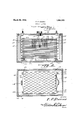
- Figure 1 is a vertical sectional View through a single cell embodying plate units constructed in accordance with my invention
- Figure 2 is a section on the line 2-2 ot Figura 1.
- the numeral 10 designates the jar which may be of any usual or preferred construction and includes the usual transversely extending legs 11 projecting upwardly from its bottom to maintain the plate assembly in spaced relation thereto.
- Each plate assembly includes a strap 12, which extends' vertieally instead of horizontally, as in the ordinary storage battery Construction and which has burned thereto a series of plates 13, which extend horizontally, the plates of one strap beingstaggered With relation to the plates of the other strap, so that they may interdigitate to produce the plate assembly.
- a Separator 14 is arranged between adjacent faces of each pair of plates.
- the plates 13 andseparators 14 are for-med at their centers with openings, designated This application filed August 11,
- each plate is provided at its opposite ends with spaced ears 19 which are apertured at 20 for the passage of vertically extending insulated rods 21.
- the rods 21 are provided at their upper ends with polygonal heads 22 pernitting application ot' a wrench thereto and at their lower ends are threaded for engagement in threaded sockets 23 produced in two of the legs 11 which align with the ears 19.
- I claim 1 In a storage battery, a cell, a plate group comprsing positive and negative connection straps extending vertically, horizontally disposed plates carried by said Straps and interdigitating inthe assembled relation thereof, separators between adjacent faces of the plates, said plates having apertures at the corners thereof and insulated rods extended through said apertures threaded'at their lower ends for engagenent in the cell bottom and at their upper ends having heads for engagenent with the upper-most plate and an electrolyte within the cell and surrounding said plates.
- a cell containing an electrolyte a plate group con'prsing' positive and negative connection straps extending vertically, horizontally disposed plates earried by said straps and intel-digitating in the' assemhled relation thereof, separator s between adjacent faces of the plate, said plates having apertures at the corners thereof and insulated rods extended through said apertures threaded at their lowerends for engagen'ent in the cell bottom and'at their upper ends having heads for engagenient with the uppernost plate, a cover for the cell having an aperture and aligning openings forned in said plates and separators and conbining to produee a well underlying the aperture of the cap and open at its opposte ends to pernit crculation' of the electrolyte therethrough.
- a cell In a storage battery, a cell, a plate group conprising positive and negative connection straps extending vertically, horizontally disposed plates carr-ed" by said sti-ups and interdigitating in the assenbled relation thereof, separators between adjaa cent faces of the plates, and means engaging said plate group at each eorner of the plates thereof and Secured at its lower end to' the cell bottom' preventing ⁇ sepamtion of the piates and naintaining the group against vertical oi' horizontal displacenent within the cell.
Landscapes
- Chemical & Material Sciences (AREA)
- Chemical Kinetics & Catalysis (AREA)
- Electrochemistry (AREA)
- General Chemical & Material Sciences (AREA)
- Secondary Cells (AREA)
Description
F" P. DANNA r STORAGE BATTERY Original Fi1ed.l
March 20, 1928.
o oo Patented Mar. 20, 1928.
UNITED STATES rrace; i
Arsi" FRANK PAUL DANNA, OF PLAQUEMINE, LOUISIANA, ASSIGNOR OF ONE-TH IRD. TO
H'D'BERT J. LAMSON, OF PLAQUEMINE, LOUISIANA.
STORAGE BATTERY.
This invention relates to storage batteries and more particular to an arrangemcnt and Construction of the platesthereot.
An important object of the invention is to provide a Construction of this character which will be very sturdy and conpact and in which it will be practieally impossible to warp, buckle or break the plates.
A further object of the invention is to provide a construetion which, in addition to preventing warping and buckling of the plates, firmly holds the plates against movement with relation to the jar, so that the chances of breakage or dislodgnent of the assenbly is materially decreased.
A further object of the invention is to provide a Construction such that loss of ac tive material from the plates and short-circuiting of the battery is prevented.
A still further object of the invention is to improve the structure illustrated in my prior application for patent on storage batteries, Serial No. 196,575, filed June 1, 1927, of which this application is a continuation.
These and other objects I attain by the Construction shown in the accompanyng drawings, wherein for the purpose of illustration is shown a preferred embodiment of my invention and wherein:-
Figure 1 is a vertical sectional View through a single cell embodying plate units constructed in accordance with my invention;
Figure 2 is a section on the line 2-2 ot Figura 1.
Referring now more particularly to the drawings, the numeral 10 designates the jar which may be of any usual or preferred construction and includes the usual transversely extending legs 11 projecting upwardly from its bottom to maintain the plate assembly in spaced relation thereto. Each plate assembly includes a strap 12, which extends' vertieally instead of horizontally, as in the ordinary storage battery Construction and which has burned thereto a series of plates 13, which extend horizontally, the plates of one strap beingstaggered With relation to the plates of the other strap, so that they may interdigitate to produce the plate assembly. Between adjacent faces of each pair of plates, a Separator 14 is arranged. The plates 13 andseparators 14: are for-med at their centers with openings, designated This application filed August 11,
preferred Construction, With the eXception of the fact thateach plate is provided at its opposite ends with spaced ears 19 which are apertured at 20 for the passage of vertically extending insulated rods 21. 'The rods 21 are provided at their upper ends with polygonal heads 22 pernitting application ot' a wrench thereto and at their lower ends are threaded for engagement in threaded sockets 23 produced in two of the legs 11 which align with the ears 19.
It will be obvious that by providing a compact structure of this character, the loss ot' n'ateri'al from the plates will be greatly reduced and the probability of short circuits occurring in the battery, due to warping of the plates, will be practically eliminated. Since the threaded rods, in addition to preventing separation of the plates, firmly hold the plate assembly to the battery jar and against either vertical or transverse novenent therein, it will be obvious that vbreakage of the straps or ot' the jar top,
which often results where the usual battery construction is subjected' to heavy jolts and Since the Construction hereinbeore set forth is capable of a certain range of change and modification without materially departing from the spiritof the' invention, I do not' limit myself to such specific structure except as hereinafter claimed.
I claim 1. In a storage battery, a cell, a plate group comprsing positive and negative connection straps extending vertically, horizontally disposed plates carried by said Straps and interdigitating inthe assembled relation thereof, separators between adjacent faces of the plates, said plates having apertures at the corners thereof and insulated rods extended through said apertures threaded'at their lower ends for engagenent in the cell bottom and at their upper ends having heads for engagenent with the upper-most plate and an electrolyte within the cell and surrounding said plates.
2. In a storage hattery', a cell containing an electrolyte, a plate group con'prsing' positive and negative connection straps extending vertically, horizontally disposed plates earried by said straps and intel-digitating in the' assemhled relation thereof, separator s between adjacent faces of the plate, said plates having apertures at the corners thereof and insulated rods extended through said apertures threaded at their lowerends for engagen'ent in the cell bottom and'at their upper ends having heads for engagenient with the uppernost plate, a cover for the cell having an aperture and aligning openings forned in said plates and separators and conbining to produee a well underlying the aperture of the cap and open at its opposte ends to pernit crculation' of the electrolyte therethrough.
3. In a storage battery, a cell, a plate group conprising positive and negative connection straps extending vertically, horizontally disposed plates carr-ed" by said sti-ups and interdigitating in the assenbled relation thereof, separators between adjaa cent faces of the plates, and means engaging said plate group at each eorner of the plates thereof and Secured at its lower end to' the cell bottom' preventing `sepamtion of the piates and naintaining the group against vertical oi' horizontal displacenent within the cell.
In testinonywhereof I hereunto my signature.
FRANKPAUL DANNA.
Priority Applications (1)
| Application Number | Priority Date | Filing Date | Title |
|---|---|---|---|
| US212306A US1663193A (en) | 1927-08-11 | 1927-08-11 | Storage battery |
Applications Claiming Priority (1)
| Application Number | Priority Date | Filing Date | Title |
|---|---|---|---|
| US212306A US1663193A (en) | 1927-08-11 | 1927-08-11 | Storage battery |
Publications (1)
| Publication Number | Publication Date |
|---|---|
| US1663193A true US1663193A (en) | 1928-03-20 |
Family
ID=22790467
Family Applications (1)
| Application Number | Title | Priority Date | Filing Date |
|---|---|---|---|
| US212306A Expired - Lifetime US1663193A (en) | 1927-08-11 | 1927-08-11 | Storage battery |
Country Status (1)
| Country | Link |
|---|---|
| US (1) | US1663193A (en) |
Cited By (2)
| Publication number | Priority date | Publication date | Assignee | Title |
|---|---|---|---|---|
| WO1982004354A1 (en) * | 1981-05-29 | 1982-12-09 | California Inst Of Techn | Improved lead-acid battery |
| US4539268A (en) * | 1981-07-02 | 1985-09-03 | California Institute Of Technology | Sealed bipolar multi-cell battery |
-
1927
- 1927-08-11 US US212306A patent/US1663193A/en not_active Expired - Lifetime
Cited By (3)
| Publication number | Priority date | Publication date | Assignee | Title |
|---|---|---|---|---|
| WO1982004354A1 (en) * | 1981-05-29 | 1982-12-09 | California Inst Of Techn | Improved lead-acid battery |
| US4405697A (en) * | 1981-05-29 | 1983-09-20 | California Institute Of Technology | Lead-acid battery |
| US4539268A (en) * | 1981-07-02 | 1985-09-03 | California Institute Of Technology | Sealed bipolar multi-cell battery |
Similar Documents
| Publication | Publication Date | Title |
|---|---|---|
| US12272843B2 (en) | Battery straps | |
| US1663193A (en) | Storage battery | |
| US2186148A (en) | Storage battery | |
| US2092214A (en) | Battery | |
| US1527426A (en) | Storage battery | |
| US1926157A (en) | Storage battery unit | |
| US1992817A (en) | Plate holddown | |
| US2646459A (en) | Electric storage battery venting system | |
| US2261597A (en) | Storage battery | |
| ES343757A1 (en) | Battery construction | |
| US1425924A (en) | Storage battery | |
| KR20230160167A (en) | Battery pack | |
| US2199229A (en) | Storage battery | |
| US1970189A (en) | Storage battery element | |
| US1656753A (en) | Storage battery | |
| US1778613A (en) | Storage battery | |
| US1035178A (en) | Electric battery. | |
| US1503070A (en) | Storage battery | |
| US1678224A (en) | Lead storage battery | |
| US1725260A (en) | Storage battery | |
| US2042515A (en) | Storage battery | |
| US1644590A (en) | Storage battery | |
| US1515738A (en) | Storage-battery separator | |
| US1425469A (en) | Electric storage battery | |
| US2247161A (en) | Storage battery |