US1663191A - Method of making valve lifters - Google Patents
Method of making valve lifters Download PDFInfo
- Publication number
- US1663191A US1663191A US543952A US54395222A US1663191A US 1663191 A US1663191 A US 1663191A US 543952 A US543952 A US 543952A US 54395222 A US54395222 A US 54395222A US 1663191 A US1663191 A US 1663191A
- Authority
- US
- United States
- Prior art keywords
- stock
- tube
- blank
- lifter
- body portion
- Prior art date
- Legal status (The legal status is an assumption and is not a legal conclusion. Google has not performed a legal analysis and makes no representation as to the accuracy of the status listed.)
- Expired - Lifetime
Links
- 238000004519 manufacturing process Methods 0.000 title description 6
- 238000000034 method Methods 0.000 description 5
- 238000002788 crimping Methods 0.000 description 3
- 238000005553 drilling Methods 0.000 description 2
- 238000003825 pressing Methods 0.000 description 2
- 239000004215 Carbon black (E152) Substances 0.000 description 1
- 241000905957 Channa melasoma Species 0.000 description 1
- 102100027069 Odontogenic ameloblast-associated protein Human genes 0.000 description 1
- 101710091533 Odontogenic ameloblast-associated protein Proteins 0.000 description 1
- 238000005520 cutting process Methods 0.000 description 1
- 229930195733 hydrocarbon Natural products 0.000 description 1
- 150000002430 hydrocarbons Chemical class 0.000 description 1
- 238000003754 machining Methods 0.000 description 1
- 239000002184 metal Substances 0.000 description 1
- 238000004080 punching Methods 0.000 description 1
- 230000002787 reinforcement Effects 0.000 description 1
- 238000010079 rubber tapping Methods 0.000 description 1
- 239000007787 solid Substances 0.000 description 1
Images
Classifications
-
- B—PERFORMING OPERATIONS; TRANSPORTING
- B21—MECHANICAL METAL-WORKING WITHOUT ESSENTIALLY REMOVING MATERIAL; PUNCHING METAL
- B21K—MAKING FORGED OR PRESSED METAL PRODUCTS, e.g. HORSE-SHOES, RIVETS, BOLTS OR WHEELS
- B21K1/00—Making machine elements
- B21K1/76—Making machine elements elements not mentioned in one of the preceding groups
-
- Y—GENERAL TAGGING OF NEW TECHNOLOGICAL DEVELOPMENTS; GENERAL TAGGING OF CROSS-SECTIONAL TECHNOLOGIES SPANNING OVER SEVERAL SECTIONS OF THE IPC; TECHNICAL SUBJECTS COVERED BY FORMER USPC CROSS-REFERENCE ART COLLECTIONS [XRACs] AND DIGESTS
- Y10—TECHNICAL SUBJECTS COVERED BY FORMER USPC
- Y10T—TECHNICAL SUBJECTS COVERED BY FORMER US CLASSIFICATION
- Y10T29/00—Metal working
- Y10T29/49—Method of mechanical manufacture
- Y10T29/49229—Prime mover or fluid pump making
- Y10T29/49247—Valve lifter making
Definitions
- the object of this invention is to provide a new and improved valve-lifter.
- the valve lifter to which the invention is directed is the plunger interposed between the cam and valve of an automobile or hydro-carbon motor.
- This plunger is usually provided with a roller which is engaged by the cam and also. with an adjusting screw which engages the lower end of the valve stem.
- valve lifter can be made by drawing a cup or tube closed at one end from flat stock in such a manner that the body portion of the blank thus formed will be as thin as desired but so so that the stock near the open end of the blank will be much thicker than the body portion and so that the bottom or closed end of the blank also body portion.
- the thicker stock around the 85 open "end of the blank is then pressed inwardly, to form a blank or tube having a uniform outside diameter, the stock near the I open end thereof being thlcker than the body portion thereof, and the bottom also being 40 thicker than the body portion.
- the blank or tube is machined and ground to make the finished lifter.
- a valve lifter is thus rovided which can be very cheaply manu actured, which is light and which ein integral cannot come to pieces in use.
- Fig. 6- is a view similar to Fig. 5;
- Fig. 7 is an end view showing the blank or tube machined
- FIG. 8 is a view showing the lifter in operatlve position.
- the portion E is then pressed or crimped in to assume the shape shown at F in Fig: 5, or in other words, a tube or blank 1s produced having a body portion F of relatively thin stock, the stock F near the open end of the tube being thicker and the bottom F of'the blank also being thicker than the body portion, said tube being integral and having a v uniform outside diameter.
- This machining consists in cutting a slot 10 across formed then is machined to y the open end thereof, in drilling a transverse" hole 11 through punching in a hole 12 in the closed end of the tube and in tapping or threading this hole. After these machine operations are performed, the lifter can be ground so as to have a uniform cylindrical diameter.
- the lifter is used by placing a roller 13 in the groove or slot 10, which roller is held in placeby apin 14 driven into the hole 11' through said roller 13, and by threading a screw 15 lnto the hole 12, ,which screw v1s usually provided with locknuts 16 and 17.
- valve lifter which consists in drawing a tube or cup from flat stock, elongating the tube so; that the body portion thereof will be thin. and so that the stock near the open end thereof will be thick, and crimping. or pressing in the stock near said open'endso to produceia blank in integral tubular form having a uniform outside diameter with the stock near the open end thicker than the body portion thereof.
- valve lifter which consists in drawing a tube or cup fromflatstock, elongating thetube .so as to provide thicker stock near the open-end, and
- valve lifter which consists indrawing a tube or cup from flat stock, elongating the tube so that the body portion thereof will be thin and so that the stock near the open end thereof will be thick, and crimping or pressing in the stock near said open end so as to produce a blank in integral tubular form having a uniform outside diameter with .the stock near the open end thicker than the body portion thereof, and then slotting and drilling the open end of'this blank.
- valve lifter which consists in drawing a tube or cup "thereof.
Landscapes
- Engineering & Computer Science (AREA)
- Mechanical Engineering (AREA)
- Forging (AREA)
Description
March 20, 1928.
H. G. CARLSON METHOD OF MAKING VALVE LIFTERS,
Filed March 15, 1922 Patented Mar. 20,1928.
UNITED! STATES PATENT orrica.
SPRINKLER ('JOIlllUPAJNY OF MASSACHUSETTS,
CORPORATION OF MASSACHUSETTS.
OF WORCESTER, MASSACHUSETTS, A
mnrnon or MAKING VALVE LIFTERS.
Application filed Mai-ch15, 1922. Serial No. 543,952.
The object of this invention is to provide a new and improved valve-lifter. The valve lifter to which the invention is directed is the plunger interposed between the cam and valve of an automobile or hydro-carbon motor. This plunger is usually provided with a roller which is engaged by the cam and also. with an adjusting screw which engages the lower end of the valve stem. These valve lifters are now usually made in one of two ways. In the first way,
stock is taken and cut and machined to obtain the desired shape. This method is expensive and makes a lifter which iscomparatively heavy. The second way these lifters are now made isto take a piece of tubular stock and insert bushings in the ends thereof to form reinforcements, the blank thus made being thereafter cut and machined to make the lifter. While this makes a lighter lifter, the method employed is expensive and the lifter being made of separate parts is apt to come to pieces under the continued reciprocation and jar in use.
I have discovered that an improved valve lifter can be made by drawing a cup or tube closed at one end from flat stock in such a manner that the body portion of the blank thus formed will be as thin as desired but so so that the stock near the open end of the blank will be much thicker than the body portion and so that the bottom or closed end of the blank also body portion. The thicker stock around the 85 open "end of the blank is then pressed inwardly, to form a blank or tube having a uniform outside diameter, the stock near the I open end thereof being thlcker than the body portion thereof, and the bottom also being 40 thicker than the body portion. Then the blank or tube is machined and ground to make the finished lifter. A valve lifter is thus rovided which can be very cheaply manu actured, which is light and which ein integral cannot come to pieces in use.
t also will be-noticedthat as the article is made from flat stock drawn or pressed into integral, tubular or cup-like form; the grain of the metal will extend continuously throughout the length thereof whereby it can be made very light and whereby the same will last a long time without wear, as
a solid piece of will be thicker than the,
it reciprocates axially in its cage or hearing.
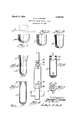
The invention is illustrated in the accompanying drawing, in which Figs. 1, 2, 3, 4 and 5 are cross-sectional views showing the drawing steps employed;
Fig. 6- is a view similar to Fig. 5;
Fig. 7 is an end view showing the blank or tube machined, and
8 is a view showing the lifter in operatlve position.
Referring to the drawing, and in detail, it will be seenthat I first take a stock A and draw the same by a suitable punch and die into a cup or tube B, as shown in Fig. 1. This cup B is then elongated by piece of flat,
another drawing process to assume the shape shown at C in Fig. 2. This cup C is then sub ected to a drawingand elongating process so that the side walls or body portion thereof will be reduced in thickness, as illus tratedat D in Fig. 3. This drawing process is then again conducted with another set of dies to produce the shape shown at E in Fig. 4, that is, a tube or blank having thin stock along its body portion E, thicker stock E around the portion near the open end of the tube, and a bottom E thicker than the body portion. The portion E is then pressed or crimped in to assume the shape shown at F in Fig: 5, or in other words, a tube or blank 1s produced having a body portion F of relatively thin stock, the stock F near the open end of the tube being thicker and the bottom F of'the blank also being thicker than the body portion, said tube being integral and having a v uniform outside diameter. The blank thus make up the completed article. This machining consists in cutting a slot 10 across formed then is machined to y the open end thereof, in drilling a transverse" hole 11 through punching in a hole 12 in the closed end of the tube and in tapping or threading this hole. After these machine operations are performed, the lifter can be ground so as to have a uniform cylindrical diameter.
The lifter is used by placing a roller 13 in the groove or slot 10, which roller is held in placeby apin 14 driven into the hole 11' through said roller 13, and by threading a screw 15 lnto the hole 12, ,which screw v1s usually provided with locknuts 16 and 17.
this thickened stock, in
The lifter with these parts is placed in position so that the roller 13 will be engaged by the cam of the motor and so that the screw 15 will engage the lower end of the valve stem, as shown in Fig. 8. Thus, a light, strong, cheap lifter is provided for v the purpose stated.
'The'details and the operations may be varied by a skilled mechanic without depart-. ing from-the scope of my invention as expressed in the claims.
Having thus fully described my invention,-
what I claim and desire to secure by Letters Patent is :i R v -1. The method of making a valve lifter which consists in drawing a tube or cup from flat stock, elongating the tube so; that the body portion thereof will be thin. and so that the stock near the open end thereof will be thick, and crimping. or pressing in the stock near said open'endso to produceia blank in integral tubular form having a uniform outside diameter with the stock near the open end thicker than the body portion thereof. V
2. The method of making a valve lifter which consists in drawing a tube or cup fromflatstock, elongating thetube .so as to provide thicker stock near the open-end, and
on the closed end portion relatively to' the body portion thereof, and crimping or forcing inwardly the thicker stock around the open end to produce a blank having a uni- "form outside diameter.
- 3. The method of making a valve lifter which consists indrawing a tube or cup from flat stock, elongating the tube so that the body portion thereof will be thin and so that the stock near the open end thereof will be thick, and crimping or pressing in the stock near said open end so as to produce a blank in integral tubular form having a uniform outside diameter with .the stock near the open end thicker than the body portion thereof, and then slotting and drilling the open end of'this blank.
4. The method of making a valve lifter which consists in drawing a tube or cup "thereof.
In testimony whereof I have hereunto affixed my signature. v. a
' HJALMAR ea, CARLSON.
Priority Applications (1)
| Application Number | Priority Date | Filing Date | Title |
|---|---|---|---|
| US543952A US1663191A (en) | 1922-03-15 | 1922-03-15 | Method of making valve lifters |
Applications Claiming Priority (1)
| Application Number | Priority Date | Filing Date | Title |
|---|---|---|---|
| US543952A US1663191A (en) | 1922-03-15 | 1922-03-15 | Method of making valve lifters |
Publications (1)
| Publication Number | Publication Date |
|---|---|
| US1663191A true US1663191A (en) | 1928-03-20 |
Family
ID=24170191
Family Applications (1)
| Application Number | Title | Priority Date | Filing Date |
|---|---|---|---|
| US543952A Expired - Lifetime US1663191A (en) | 1922-03-15 | 1922-03-15 | Method of making valve lifters |
Country Status (1)
| Country | Link |
|---|---|
| US (1) | US1663191A (en) |
Cited By (3)
| Publication number | Priority date | Publication date | Assignee | Title |
|---|---|---|---|---|
| US4850315A (en) * | 1988-05-27 | 1989-07-25 | The Budd Company | Push rod |
| US5027763A (en) * | 1989-12-05 | 1991-07-02 | Mall Tooling And Engineering | One-piece push rod having enlarged spherical seat |
| US5069173A (en) * | 1989-12-05 | 1991-12-03 | Mall Tooling And Engineering | Push rod having irregularly shaped internal bore |
-
1922
- 1922-03-15 US US543952A patent/US1663191A/en not_active Expired - Lifetime
Cited By (3)
| Publication number | Priority date | Publication date | Assignee | Title |
|---|---|---|---|---|
| US4850315A (en) * | 1988-05-27 | 1989-07-25 | The Budd Company | Push rod |
| US5027763A (en) * | 1989-12-05 | 1991-07-02 | Mall Tooling And Engineering | One-piece push rod having enlarged spherical seat |
| US5069173A (en) * | 1989-12-05 | 1991-12-03 | Mall Tooling And Engineering | Push rod having irregularly shaped internal bore |
Similar Documents
| Publication | Publication Date | Title |
|---|---|---|
| US2038475A (en) | Antifriction bearing and method of making the same | |
| US2077336A (en) | Apparatus for forming circular bushings | |
| US2969030A (en) | Production of writing tips | |
| US3399560A (en) | Method of cold forming a solid ring | |
| US2028996A (en) | Manufacture of cartridge case cups | |
| US1663191A (en) | Method of making valve lifters | |
| US1387638A (en) | Process of making cup and cone members for roller-bearings | |
| US2150708A (en) | Method and apparatus for making tubes | |
| US1949618A (en) | Method of making drain valves | |
| US2813279A (en) | Method of making hexagon socket type cup point set screw blanks | |
| US9120143B2 (en) | Cut-off end surface improvement | |
| US1054669A (en) | Process of making a combined bolt and grease-cup from sheet-metal blanks. | |
| US1225915A (en) | Process for making grease-cup bodies. | |
| US1147273A (en) | Dies. | |
| US2133467A (en) | Method and apparatus for making knurled socketed screws | |
| US1152983A (en) | Process for forming a sheet-metal sheel for a spark-plug. | |
| US1503023A (en) | Method of making articles of pressed metal | |
| US2177192A (en) | Method of making hollow articles | |
| US2743466A (en) | Method of making skirted nuts | |
| US1200309A (en) | Method of metal-drawing. | |
| US1449505A (en) | Feed collet and method of making the same | |
| US1243818A (en) | Method of producing hollow set-screws. | |
| US1886210A (en) | Method of making cupped forgings | |
| PH12016000060A1 (en) | Poppet pin ejector | |
| US1486280A (en) | Method of making chuck sleeves |