US1663179A - Renewable fuse - Google Patents
Renewable fuse Download PDFInfo
- Publication number
- US1663179A US1663179A US134725A US13472526A US1663179A US 1663179 A US1663179 A US 1663179A US 134725 A US134725 A US 134725A US 13472526 A US13472526 A US 13472526A US 1663179 A US1663179 A US 1663179A
- Authority
- US
- United States
- Prior art keywords
- fuse
- link
- renewable
- cap
- caps
- Prior art date
- Legal status (The legal status is an assumption and is not a legal conclusion. Google has not performed a legal analysis and makes no representation as to the accuracy of the status listed.)
- Expired - Lifetime
Links
Images
Classifications
-
- H—ELECTRICITY
- H01—ELECTRIC ELEMENTS
- H01H—ELECTRIC SWITCHES; RELAYS; SELECTORS; EMERGENCY PROTECTIVE DEVICES
- H01H85/00—Protective devices in which the current flows through a part of fusible material and this current is interrupted by displacement of the fusible material when this current becomes excessive
- H01H85/02—Details
- H01H85/04—Fuses, i.e. expendable parts of the protective device, e.g. cartridges
- H01H85/05—Component parts thereof
- H01H85/143—Electrical contacts; Fastening fusible members to such contacts
- H01H85/157—Ferrule-end contacts
Definitions
- This invention relates to renewable fuses and in particular to a fuse which can be made of few parts and which can be quickly renewed after the same accomplishes its purose.
- a particular object of the invention is to provide a renewable fuse which can be produced at low cost due to the fact that all of the parts can be pressed or moulded and quickly assembled.
- a further particular object of the invention is to provide a fuse which will prevent overheating of the body portion thereof due to the fact that the fuse body is arranged so that it does not come into contact with the fusible parts of the links thereby preventing the body from becoming overheated at any point and also providing a body portion which, in itself, will cool the fuse link body by being in contact therewith, so that the fuse link itself will not be overheated except where it is desired to have it melt in the case of an overload.
- a further, particular object of the invention is to provide a renewable fuse which maybe pulled apart in two halves and in which a new fuse link may be inserted, the parts to he slipped together again whereby awkward renewal of the fuse, dropping of screws, washers, etc., with a consequential loss of time and parts will be eliminated.
- a further, particular object of the invention is to provide in a fuse member a perfect spring contact, thereby eliminating the use of screws and loose parts which cause sparks and resulting in short circuit which blow the fuse unnecessarily 7
- a drawing depicting a preferred form has been annexed as a part of this disclosure and in such drawings, similar reference characters denote corresponding parts throughout all the views, of which,
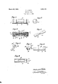
- Figure 1 is a view in side elevation of my improved renewable fuse
- Figure 2 is a view in end elevation there- 0
- Figure 3 is a longitudinal, cross section link which I employ in my improved renewable fuse.
- Figure 5 is a view in perspective of the contact spring used as a part of the fuse.
- Figure 6 is a side view in elevation of one of the body portions of my improved fuse.
- Figure 7 is a section taken on the line 7 7 of Figure 6 showing the construction of said body portion
- Figure 8 is a top plan view of one-half of the fuse body. as illustrated in Figure 6, showing the construction thereof.
- 5 indicates my improved renewable fuse, which consists of the end metal caps 6 and 7 and in view of the fact that both ends of the fuse are alike, it will suflice to describe the construction of one-half of the fuse, the body portion thereof consisting of two parts 8 and 9 which are substantially alike and which consist of an extended portion 10 and an end head portion 11, the substance thereof being porcelain or other like material or of any suitable water and heat proof dielectric substance, the end 11 of the body being enlarged to receive the metal cap 6 and being provided with a circumferential groove 12 therein, the purpose of which will be hereinafter described.
- the body member 10 is cut on a horizontal plane to provide the shelf 13 and side ledges 14. and 15, all of which match and cooperate with the adjoining half of the body 8 to provide the completed fuse body.
- the shelf 13 provides in the center of the fuse, a longitudinally exfending chamber in which is disposed the .fuse link 16, which, as shown in Figure 4,
- a contact spring member 19 which is provided with a cap engaging portion 20 and a spring lip 21, the cap engaging portion 20 being adapted for soldering or other suitable connection to the interior of the cap end 6, while the intermediate portion of the contact spring is adapted to pass through a suitable groove 22 provided in the periphery of the enlarged end 11 of the fuse body.
- the contact spring portion 21 being arranged to lie within the longitudinal chamber formed between the two halves of the body member, as hereinbefore referred to, and adapted to retain in position the end of the fuse link so that the same passes diagonally from one side of the chamber to the other and is so disposed that its reduced portion is adjacent'the air chamber 19, formed in the fuse body.
- separation of the fuse body means only the drawing apart of the fuse cap, each of which will carry with them one-half of the fuse body so that the fuse links may be removed and a new one inserted in its place after which the free ends of the body portions of the fuse may be placed within the cap and secured therein frictionally.
- a still further advantage obtained by the use of my fuse is the low cost of producing the same over other fuses of this type due to the fact that all of the parts of the fuse can be pressed or moulded.
- l have provided a fuse body which will have a cooling effect when in contact with the fuse member thereby preventing the latter from overheating anywhere but at the point where it is desired to have it melt in case of an overload of current.
- a renewable fuse comprising separable body portions, a link positioned between said body-portions, end caps for releasably holding said body portions together, and contact springs connecting the link and said end caps.
- a renewable fuse comprising separable body portions having formed therein air chambers, a fusible link, held between said body portions and having a reduced portion adjacent said chamber, end caps for re leasably holding said body portions together, and contact springs connecting the link and said end caps.
- a refillable fuse comprising separable body portions, caps for the ends of said body portions, contact springs carried by said caps and arranged to retain the body portions within said caps, the body portions when put together forming a chamber, a fuse link in said chamber, and said springs being arranged to hold the link in place between said body portion.
- a refillable fuse comprising separable body portions having air chambers therein, caps for the ends of said body portion, con; tact springs secured to said caps and arranged to retain the free ends of the body portion frictionally within said cap, the body portions when put together forming a chamber, a fuse link having a reduced portion in said chamber and said springs being arranged to hold the link in place between said body portion.
Landscapes
- Fuses (AREA)
Description
March 20, 1928. 1,663,179
F. J. ROTH RENEWABLE FUSE Filed Sept. 10. 1926 INVENTOR ATTORNEY Patented Mar. 20, 1928.
UNITED STATES FREDERICK J ROTH, OF NEW YORK, N. Y.
RENEWABLE FUSE.
Application filed September 10, 1926. Serial No. 134,725.
This invention relates to renewable fuses and in particular to a fuse which can be made of few parts and which can be quickly renewed after the same accomplishes its purose. p A particular object of the invention is to provide a renewable fuse which can be produced at low cost due to the fact that all of the parts can be pressed or moulded and quickly assembled.
A further particular object of the invention is to provide a fuse which will prevent overheating of the body portion thereof due to the fact that the fuse body is arranged so that it does not come into contact with the fusible parts of the links thereby preventing the body from becoming overheated at any point and also providing a body portion which, in itself, will cool the fuse link body by being in contact therewith, so that the fuse link itself will not be overheated except where it is desired to have it melt in the case of an overload.
A further, particular object of the invention is to provide a renewable fuse which maybe pulled apart in two halves and in which a new fuse link may be inserted, the parts to he slipped together again whereby awkward renewal of the fuse, dropping of screws, washers, etc., with a consequential loss of time and parts will be eliminated.
A further, particular object of the invention is to provide in a fuse member a perfect spring contact, thereby eliminating the use of screws and loose parts which cause sparks and resulting in short circuit which blow the fuse unnecessarily 7 To enable others skilled in the art to fully comprehend the underlying features of my invention that they may embody the same in the various modifications in structure and relation contemplated, a drawing depicting a preferred form has been annexed as a part of this disclosure and in such drawings, similar reference characters denote corresponding parts throughout all the views, of which,
Figure 1 is a view in side elevation of my improved renewable fuse,
fFigure 2 is a view in end elevation there- 0 Figure 3 is a longitudinal, cross section link which I employ in my improved renewable fuse.
Figure 5 is a view in perspective of the contact spring used as a part of the fuse.
Figure 6 is a side view in elevation of one of the body portions of my improved fuse.
Figure 7 is a section taken on the line 7 7 of Figure 6 showing the construction of said body portion, and
Figure 8 is a top plan view of one-half of the fuse body. as illustrated in Figure 6, showing the construction thereof.
Referring to the drawings in detail, 5 indicates my improved renewable fuse, which consists of the end metal caps 6 and 7 and in view of the fact that both ends of the fuse are alike, it will suflice to describe the construction of one-half of the fuse, the body portion thereof consisting of two parts 8 and 9 which are substantially alike and which consist of an extended portion 10 and an end head portion 11, the substance thereof being porcelain or other like material or of any suitable water and heat proof dielectric substance, the end 11 of the body being enlarged to receive the metal cap 6 and being provided with a circumferential groove 12 therein, the purpose of which will be hereinafter described. The body member 10 is cut on a horizontal plane to provide the shelf 13 and side ledges 14. and 15, all of which match and cooperate with the adjoining half of the body 8 to provide the completed fuse body. The shelf 13 provides in the center of the fuse, a longitudinally exfending chamber in which is disposed the .fuse link 16, which, as shown in Figure 4,
comprises the enlarged end 17 and reduced mid section 18, the latter of which is disposed when in normal position within the fuse body between two suitable air chambers 19 whichare provided by notching or grooving the shelf 13 at the middle of the body portion 10. This notching or grooving providing an air chamber in which the fuse link or portion 18 may freely melt. In order to hold the link in position, I provide on the interior of the cap 6, a contact spring member 19, which is provided with a cap engaging portion 20 and a spring lip 21, the cap engaging portion 20 being adapted for soldering or other suitable connection to the interior of the cap end 6, while the intermediate portion of the contact spring is adapted to pass through a suitable groove 22 provided in the periphery of the enlarged end 11 of the fuse body. The contact spring portion 21 being arranged to lie within the longitudinal chamber formed between the two halves of the body member, as hereinbefore referred to, and adapted to retain in position the end of the fuse link so that the same passes diagonally from one side of the chamber to the other and is so disposed that its reduced portion is adjacent'the air chamber 19, formed in the fuse body.
In order to effectively hold the fuse body together, I provide in the cap, a-fter placing the same over the ends of the body, a suitable rolled groove 22 which effectively crimps the contact spring into the groove 12, formed in the end of the body portion, the groove 22 of the cap fitting snugly into the groove 12 of the body portion and thereby retaining within the cap through the medium of the contact spring, the spring itself end also one-half of the body portion of the use.
lit is evident therefore, that separation of the fuse body means only the drawing apart of the fuse cap, each of which will carry with them one-half of the fuse body so that the fuse links may be removed and a new one inserted in its place after which the free ends of the body portions of the fuse may be placed within the cap and secured therein frictionally.
It is also evident that perfect contact will be made between the caps 6 and 7 and the fuse links through the medium of the contact springs 21 which not only function to hold the links securely in place but also act to retain the body portion of the fuse body in their place within the cap members 6 and 7.
llt has always been very dificult to renew the fuse links of the so-called renewable fuses, due to the fact that the parts of the body and end caps thereof have been put together with screws and other holding means, which, when removed from the fuse so that the same can be renewed, are subject to loss and consequently loss of time spent looking for the same, thereby reducing the efficiency of the electrical worker or other person employed in the replacing of fuses, which is commonly necessary in large manufacturing establishments and. in other places employing electric current to carry on various kinds of work, in which overload may occur and does occur frequently.
It is evident, therefore, that if have provided a renewable fuse which eliminates the awkward way of renewing other fuses through the dropping of screws and wash ers and consequent loss of time in looking for the same. In my fuse, it is simply necessary to pull the two halves of the fuse apart, insert the new member and slip the halves together and a substantially new fuse is completed.
A still further advantage obtained by the use of my fuse is the low cost of producing the same over other fuses of this type due to the fact that all of the parts of the fuse can be pressed or moulded.
It is also evident that l have provided a spring contact for the fuse member which will not become loose thereby causing sparking and blowing of the fuse unnecessarily.
t is also evident that l have provided a fuse body which will have a cooling effect when in contact with the fuse member thereby preventing the latter from overheating anywhere but at the point where it is desired to have it melt in case of an overload of current.
lVhile l have illustrated and described my invention with some degree of particular ity, ll realize that in practice various alter ations therein may be'made. I therefore reserve the right and privilege of changing the form of the details of construction or otherwise altering the arrangement of the correlated parts without departing from the spirit of the invention or the scope of the appended claims.
Having thus described my invention what if claim as new and desire to secure by United States Letters Patent is:-
l. A renewable fuse comprising separable body portions, a link positioned between said body-portions, end caps for releasably holding said body portions together, and contact springs connecting the link and said end caps.
2. A. renewable fuse comprising separable body portions having formed therein air chambers, a fusible link, held between said body portions and having a reduced portion adjacent said chamber, end caps for re leasably holding said body portions together, and contact springs connecting the link and said end caps.
3. A refillable fuse comprising separable body portions, caps for the ends of said body portions, contact springs carried by said caps and arranged to retain the body portions within said caps, the body portions when put together forming a chamber, a fuse link in said chamber, and said springs being arranged to hold the link in place between said body portion.
4. A refillable fuse comprising separable body portions having air chambers therein, caps for the ends of said body portion, con; tact springs secured to said caps and arranged to retain the free ends of the body portion frictionally within said cap, the body portions when put together forming a chamber, a fuse link having a reduced portion in said chamber and said springs being arranged to hold the link in place between said body portion. 4
In testimony whereof I afiix my signature.
FREDERICK J. ROTH. [L a]
Priority Applications (1)
| Application Number | Priority Date | Filing Date | Title |
|---|---|---|---|
| US134725A US1663179A (en) | 1926-09-10 | 1926-09-10 | Renewable fuse |
Applications Claiming Priority (1)
| Application Number | Priority Date | Filing Date | Title |
|---|---|---|---|
| US134725A US1663179A (en) | 1926-09-10 | 1926-09-10 | Renewable fuse |
Publications (1)
| Publication Number | Publication Date |
|---|---|
| US1663179A true US1663179A (en) | 1928-03-20 |
Family
ID=22464695
Family Applications (1)
| Application Number | Title | Priority Date | Filing Date |
|---|---|---|---|
| US134725A Expired - Lifetime US1663179A (en) | 1926-09-10 | 1926-09-10 | Renewable fuse |
Country Status (1)
| Country | Link |
|---|---|
| US (1) | US1663179A (en) |
Cited By (2)
| Publication number | Priority date | Publication date | Assignee | Title |
|---|---|---|---|---|
| US2759065A (en) * | 1955-01-10 | 1956-08-14 | Moeller Arthur Edward | Fuse holder |
| US3378659A (en) * | 1967-04-24 | 1968-04-16 | Chase Shawmut Co | Cartridge fuses |
-
1926
- 1926-09-10 US US134725A patent/US1663179A/en not_active Expired - Lifetime
Cited By (2)
| Publication number | Priority date | Publication date | Assignee | Title |
|---|---|---|---|---|
| US2759065A (en) * | 1955-01-10 | 1956-08-14 | Moeller Arthur Edward | Fuse holder |
| US3378659A (en) * | 1967-04-24 | 1968-04-16 | Chase Shawmut Co | Cartridge fuses |
Similar Documents
| Publication | Publication Date | Title |
|---|---|---|
| US1663179A (en) | Renewable fuse | |
| US1579596A (en) | Electric fuse and method of preparing same | |
| US2256716A (en) | Fuse for outlet connections | |
| US1952279A (en) | Fuse plug for electric light switch boxes | |
| US1353123A (en) | Cartridge-fuse | |
| US1485211A (en) | Renewable electric fuse | |
| US1857098A (en) | Renewable fuse element | |
| US1296808A (en) | Inclosed fuse. | |
| US1266479A (en) | Fuse. | |
| US2501996A (en) | Fuse plug | |
| US1601726A (en) | Fuse | |
| US1749364A (en) | Radio receiving apparatus | |
| US1388269A (en) | Inclosed or cartridge fuse | |
| US2471177A (en) | Renewable fuse | |
| US1463885A (en) | Cartridge fuse | |
| US1435155A (en) | Fuse cartridge | |
| US1337949A (en) | Electric fuse | |
| US1207351A (en) | Electric fuse. | |
| US1744019A (en) | Refillable fuse | |
| US1968361A (en) | Night light transformer | |
| US1819910A (en) | Electrical attachment plug | |
| US1650462A (en) | Fuse plug | |
| US1928997A (en) | Electric fuse | |
| US1419226A (en) | Cartridge fuse | |
| US1958366A (en) | Electric fuse |