US1663174A - Cigar-bunch-making machine - Google Patents
Cigar-bunch-making machine Download PDFInfo
- Publication number
- US1663174A US1663174A US109804A US10980426A US1663174A US 1663174 A US1663174 A US 1663174A US 109804 A US109804 A US 109804A US 10980426 A US10980426 A US 10980426A US 1663174 A US1663174 A US 1663174A
- Authority
- US
- United States
- Prior art keywords
- shaft
- fastened
- arm
- cam
- chamber
- Prior art date
- Legal status (The legal status is an assumption and is not a legal conclusion. Google has not performed a legal analysis and makes no representation as to the accuracy of the status listed.)
- Expired - Lifetime
Links
Images

Classifications
-
- A—HUMAN NECESSITIES
- A24—TOBACCO; CIGARS; CIGARETTES; SIMULATED SMOKING DEVICES; SMOKERS' REQUISITES
- A24C—MACHINES FOR MAKING CIGARS OR CIGARETTES
- A24C1/00—Elements of cigar manufacture
- A24C1/08—Making tobacco bunches
Definitions
- This invention relates to a cigar' bunch making machine, and a substitute or'the lapplication filed September 18th, 1920, Se-
- the object of the invention is the production of a machine for forming the filler with its binder which constitutes the bunch for the cigar to be manufactured.
- the machine can be provided with various shaped ycollectingchambers which impart the initial shape. to the filler, andl rolling i means which subsequently shape thevfiller,
- Fig. l1 represents aside elevation of the cigar' bunching machine
- Fia'. 2 is a top plan View of Fig. l; Fig. 3
- Fig. ⁇ 4 is an enlarged section of Fig. ⁇ 2 on the line 4, 4: Fig. 5 represents an enlarged lett hand side view of Fig. l;
- Fig. 6 shows a section on the line 6, 6 of,v
- Fig. 3 shows a section .of Fig. ⁇ 1l on j the line 7. 7 Fig. 8 shows an 'elevation of one ot the cams of the machine.; Figs. 91
- Fig'. 11 shows :i modified torni o'l vcam with its Aappurtenances
- Fig. 12 shows a section on the une i2 of Fig. 11.
- the machine comprises the base plate on which are mounted the parallelframes indicated in their entireties by the numerals A and li.
- the trame A comprises the upper horizontal member 21 which has formed therewith the legs 22. 24 and 25.
- the leg 24 has toi-med .therewith the journal bearings 2G and 27.
- rlhe leg 25 has formed therewith tirety by the letter C, and comprises thel YThe operations of the machine automatiside walls and 46. which are connected by the end walls 47 and 48.
- Lugs 49 are'formed withthe said end walls and are bolted to the frames A and B.
- a cylindrical shaped 4receiving pocketl 50 extends between the frames 45 and'46.
- Guides 51 are formed with the side walls 45 and y46 on the opposite ends of the pocket 50.
- a suction table 52 withfthe openings 53 extends between the walls 45v and 46 with one end thereo .connected to the receiving pocket 50.
- a delivery pocket 54 is formed between the walls 45 and 46 and is connected to the suction table by the inclined connectingA wall 55. Opening lugs 58 and. 59 extend upy from 'the sidel walls 45 and 46. Supportinglegs 61 extendrfrom vthe pocket andare con- 'nectedto the base plate 20.
- a suetionyfan 62 is supported'on the base plate 20.
- a suction chamber 63 is fastened to the lower iace of the suction table 52 and isconnected' Ato the ⁇ suction i'an by the piping 64.v Ab'ranch lpipe 64.a connects the openings 51.l in -the pocket 50 with the piping 64.
- Discharge piping 65 leads from the fan 60.
- i i v Avcollecting chamber is indicated in its entirety by the letterD and comprises the straight front wall 70, the curved rear wall 71, and the straight side wallsv 72, 73.
- a foot flange 74 at the bottom of the chamber is bolted to the base plate 2O.V
- a vertical slot 7,5 is formed in the front wall 70.
- a charging hopper 76 is tormed'with the top open end aoi the said chamber.
- Journal brackets 77, 78 and 79 are bolted to the front wall 70.
- a screw 80 is journaled at its top and bottom ends in the journal brackets 79 and 7 7 respectively.
- a bevel gear 81 is fastened to the lower end of the screw 80.
- a journal bracket 82 is bolted to the base plate 20.v
- a sliaft83 is journaled in the journal brackets"'(v 8 and V82 and has fastened to one end thereof the bevel gear 84 which meshes with the bevel gear 8l.
- a ratchet wheel 85 isfastened to the other end of the shaft 83.
- Pairs of journal brackets 90 and 91 are boltedto ythe frontwall 7 0 of the chamberl D.l
- a shaft 92 is supported in the-brackets 90 and a shaft 93 is supported in the brackets 91.
- each of the similar links 94 On the shaft 92 are iastenedone end of each of the similar links 94. To the other ends of said links 94 arel pivoted the links 95 by means of the pivots 96. A shaft 97 is supported in the other ends of the links 95 and a plurality of knife blades 98 are earried on the shaft 97. The said knife blades in one of their positions extend through a ⁇ plurality of openings 99 formed in the upper end of the front wall 70. A bracket with the similar side walls 100 and the curved Abottom 101 is fastened to the upper end of .the side walls 72 and 73 of the chamber D and said bottom extends across the width of said chamber. Guide sleeves 105 are fastened to the side walls 72 and 73 of the chamber D.V Guide rods 107 at one are pivoted to the shaft 97 and are guided in the guide sleeves 105 .to maintain the knife ⁇ blades 98 in proper operative position.
- Av pair of links 110 have one end each fastened to the shaft 93 and to their other ends are pivoted one end each of the links 111.
- Apusher 112 is pivoted to the other ends of the links-111.
- a supporting bracket 113 is fastened4 to the wall 71 of the chamber D for the said pusher 112.
- a pair of brackets 114 v are fastened to the wall 71 of the chamber D and have each formed therewith a buffer sleeve 115, in each of which is located a Y spring 116.
- a plunger 117 bears on each ,of
- An oscillating shaft 132 is supported in the bearings 32 and 41 and has fastened thereto at onel end the gear segment 133 which meshes with a gear segment of a cam to be described.
- a pair of arms 134 have one end each fastened to the shaft 132 and are conf nected at their other ends by the push bar ported on the tracks 145.
- Side knife blades 136 are fastened toY the arms 134.
- An oscillating shaft 140 is ported on the shaft 146.
- Side openings 149* are formed with the portion 149.
- a second jaw 151 with therear cylindrical portions 152 and the front cylindrical Vportion 153 has its portions 152 in contact with the shaft 146.
- Side openings 153a are formed with the portion 153.
- the vportions 149 and 153 constitute a cigar mould M.
- Pairs of opening lugs 154 and 155 are re spectively formed with the .portions 148 and 152. Pairs of spring supporting lugs 156 and 157 are formed with the portions 148 and 152.
- a segmental cylindrical shaped knife blade 160 bears up against the inner surface of the cylindrical portion 149 and has extending therefrom the guide lug 161 which latter is Aguided in the guide opening 150.
- a cross pin 1612L extends through the lug l161.
- a spring 162 has one end fastened to the guide lug 161 and its other end is fastened "to the cylindrical portion 149.
- Links 166 have the eyelets 167 at one end whichencircle the shaft 146, and at the other ends of the links are formed the eyelets 168.
- a cross bracket 169 connects the links 166.
- a pusher rod 175 with the pusher disc 176 extends through openings in the jaws 147 and 151 and through an opening 177 in theshaft 146.
- the disc 176 extends the whole length of the mold.vv
- the rod '175 also extends through an opening in the cross bracket 169.
- ⁇ A spring 178 eneircles the rod 175 and bearsbetween the cross bracket 169 and a pin 179 extending through the rod 17
- Two pairs of leaf springs 180 and 181 extend from the cross bracket 169'and bear upon the supporting lngs156 and 157v respectively. rThe springs 180 and 181 normally maintain the jaws 147 and 151 in their closed position.
- The'link 184 has formed therewith an extension leg 188 having a journal bearing 189.
- kJournal brackets 193 are fastened to the frames A. and B and' support the shaft 187.
- a spur gear 194 is fastened to one end of the shaft 187.
- a pair of brackets 195 are fastened to the base plate 20 and have supported therein the shaft 196.
- a link 200 adjacent to the frame B has one end supported on lthe shaft 196 and to its other end is c-onnected a.
- a lever E with the arms 205 and 206 has Vformed therewith a hub 207 which is sup- Vported on the shaft 196.
- a bracket 21.5 is fastened to the base plate 20 adjacent to the frame A and supports the oscillating shaft 216, on one endof which lat-ter is fastened the spur gear 217, and at the other end is fastened the oscillating arm 218 with the ear 219.
- Thearm 218 has formed at its upper end a guide and supporting cavity 220 for the extension arm 221 having the eyelet end 222. Adjacent to the frame B there is fastened to the 4base plate 20.
- a bracket 225 similar tof2'15.
- An oscillating shaft 226 similar to 216 is supported in the bracket 225.v
- a spur gear 227 similar to 217 is fastened to the shaft 226 at one end thereof.
- the oscillating arm 228 similar to 2184 and. which has formed therewith an ear 229.
- the arm 228 has formed at its upper end a guide and supporting cavity 230, for the extension arm 231 similar to the arm 221 and which has formed therewith an eyelet 232 similar to 222.
- a cross shaft 235 is slidably supported in the eyelets 222 and 232.
- a roller 236 is fastened
- a shaft 240 is journaled in the frames A and B as well as in the frames and 46. At the endsy of' the shaft 240 are fastened the grooved pulleys 241.
- Rubber cords 242 have'one end each connected to the ears 219 and 229 and are then wound around the pulleys 241 and' connected thereto.
- a canvas apron 245 has one end fastened to the connecting wall 55, is guided over the roller 236 and its other end is wound around the shaft 240 andfastened thereto.
- a plurality of scrapers 260 are fastened to the shaft 255 and are aligned in the clearance spaces be tween the knife blades 98 and the swinging pressers 141.
- the arm 253 there are secured a plurality of similar pins 262, 263, 264, 265 and 266. Each of the latter pins has formed therewith a head 268 and is secured in place to the arm 253 by means 'of the locking pin 269.
- a roller 270 is journaled on each of the pins 262 to 266.
- a cam 275 rides on the roller 270' of the Vpin 262 and is fastened to an arm 276. The end of the arm 276 is fastened tothe shaft 92.
- a bracket 278 extends up from the base plate 20 and has pivoted in .its top end the arm 279 by means of the pivot 280. At one end of the arm 279 is fastened the cam 281 which engages the roller 270 of the pin 263. The other end of the arm 279 is pivoted t0 the link 129 by means ofthe pivot 131.
- cam 285 rides on the roller 270 of the pin r291 at the upper end of the arm 290 extends across the width of the chamber D. .
- the arm 290 has also formed therewith the gear segment 292 whieh-"n'leshes with the gear segment 133.V
- a shaft 293 is supported in the bearing 33 and in turn 'is fastened to the arm 290.
- a cam 295 rides on the roller 270 of the pin 266 and is fastened to an arm 296. The latter arm is fastened. to the shaft 140.
- a kicker 298 is fastened to the arm 2,53.
- Onthe shaft 83 is fastened an arm 299 which has pivoted thereto a paivl 300. The latter coacts With ⁇ the ratchet wheel 85.
- a shaft, 322 is journaled in the bracket 320.
- a cam 325 having formed therewith thegear segment 326 is journaled on the shaft 322.
- a roller similar to 270 of the'pin 210 rides on the cam 325.l meshes with the gear 217. The coaetion of the ⁇ ear segment 326 and the gear 217 0scillates the arm 218.
- the bracket 321 is fastened a shaft 330.
- a cam 331 having formed therewith a gear segment 332 is journaled on t-he shaft 330.
- the roller similar to 270 of the pin 201 rides inthe cam 331.
- the gear segment 332 meshes with the spur gear 227. lThe -coaction of the gear segment 332 and the gear' 227 oscillates the arm 228.
- a chamber Da with the curved front. and rear walls iL and 71 is used.
- a chamber Db with the parallel iront and rear walls 7 Ob and 71b is used.
- Figs.Y 11 and 12 show a modification of the cams.
- the cam movements are changed when moving in reverse directions.
- rlhe cam comprises the body portion 335 in which is formed the main groove 336 that connects with the secondary groove 337.
- a pivoted stop 338 is normally located in the groove
- a roller rides in the groovei336 in oneA direction and on its return to its original position rides for a part ot its travel in both of the grooves 336 and 337, as the stop directs the pin into the latter groove.
- a plate is bolted to the portion 335 4ot the cam and carries the triangular block 341 which with the said portion 335. forms the grooves ot the cam.
- the rotati ons ot the shaft 83 through the intervention ot the bevel gears 84- and 81 turns the screw 80. Vithfthe rotations of the screw 80, the bottom 88 of the chamberfD rises and carries up the requisite quantity of tobacco for one bunch at each ⁇ cycle ot the ⁇ machine.
- the cam 281 by reason ot its coaction with the roller 27 O on the pin 263 lowers the pres-ser cover 127 and presses the tobacco at the upper opening of the collecting chamber D, while the arms 253 and 254 swing in the direction ot the arrow G (Fig. ⁇ 1).
- the scrapers 260 which are fastened to the shaft pnsh the severed portion of the tobacco over the curved bottom 101 into the cavity H.
- the swinging pressers 141 have been previously swungopen in the direction of the arrow I during the swing of the arm-s 253 and254 in a direction opposite the arrow Gr, by virtue of the coaction of the roller 270 of the pin 266 and the cam 295.
- the press ers 141 now swing down and bear upon the tobacco in the cavity H during ⁇ the end of the swingof the arms and 254 in the direction opposite to the arrow (l.
- the rblade 160 cnts ott the tobacco in the mold M from the tobacco in the cavity H and the blades 136 cut off( the ends of the tobacco that project through the ends ot' the mold M. lVhile the mold M is being .filled with tobacco the disc 176 is pushed back in the direction ot the arrow K (Fig. 3) against the tension of the spring 178. .
- the arm 291 maintains the supporting block 118 in proper position when the cavity H is being ⁇ ,filled with tobacco and. when it is forced out of thesame.
- a cigar bunch making machine the combination of a collecting chamber for a charge of tobacco, means to simultaneously compress and discharge the tobacco from one end of the chamber, means to severpredetermined portions of the tobacco after being discharged from the chamber, means to convey Vthe severed portions to a cavity, a mold with hinged portions in the machine, means to compress each severed portion in said cavity and force it into said mold to give it its proper shape, a table in the machine, a. movable apron on the table, means to deposit each shaped severed portionk on the apron and means to roll a binder placed on the apron around each'shaped and severed portion to make bunches for cigars.
- a. cigar bunch making ⁇ machine the combination of a driving shaft, a collecting chamber open at one end in the machine, a movable bottom in the chamber, means between the driving shaft and said bottom to move the latter, a presser cover swinging over the open end of the collecting chamber, knife bladesswinging over the open end of the chamber, Scrapers moving over the open end of the chamber, the coaction of said elements forcing port-ions of tobacco lout of said chamber, severing said portions and moving the severed portions from the open end of the chamber, means to shape.
- said severed portions and means to roll a binder on each severed portion to form a bunch for a cigar.
- a cigar bunch making machine the combination of means to compress a charge of tobacco, means to sever portions from said charge, a spring actuated 'plunger in the machine, a movable pusher in the machine coacting with said plunger to com'- press the severed portions of tobacco, an adjustable spring actuated mold coacting with said plunger to open the latter, means todischarge the severed'portions of tobacco from said mold and means toroll a binder on each severed portionrof tobacco after it leaves the' mold.
- a collecting chamber open at one end to compress a charge of tobacco, means to force said charge throughthe open end of the chamber, means to sever portions of said charge as it is discharged from the openendfof the collecting; chambeiya receiving pocket in the machine for the said severedportions, suc-tion means connectedto the pocket, vasuction table adjacent Vto said pocket, a flexible apron over said pocket and table, a mold with flexibly actuated portions adapted lto receive thesevered portions of tobaccoanddeposit them upon the apron intov said pocket, .a-pair of 'shaft-s journaled'under ⁇ the suction table, a pair of arms with one end of each fastenedto each shaft and a roller journaled in the swinging ends of said arms, said roller contacting with the lower face of said apron and adaptedv to roll lsaid severed portions of tobacco upon said apron from said pocket over said suction table
- a cigar-bunch making machine the combination of a collecting chamber open at one end, a presser cover over said open end, an oscillating arm adjacent to said chamber, a pin on the arm, a cam pivoted adjacent to the oscillating arm with its cam surface coacting with said pin and connecting means between the other end of the cam vand said presser cover.
- a cigar bunch making machine the combination of a collecting chamber open at one end, an. oscillating arm adjacent to said chamber, a pin on said arm, a cam pivoted adjacent to said chamber with its cam surface coacting with said pin, an oscillating shaft supported adjacent to lthe chamber, a link with one end fastened to the shaft, a second link connecting the first link and the said cam and a presser cover over the chamber With one end fastened to said shaft.
- a cigar bunch making machine the combination of a pusher slidably supported, a shaft journaled below the pusher, an oscillating'arm in the machine, a pin extending from the arm, a cam with ⁇ one end fastened t0 the shaft and Aits cam surface coacting with the pinand linked connections betwecz'i the -shaft and pusher to reciprocate thelatter.
- a cigar bunch making machine the combination of a mold for a material, a knife blade for the mold to cut the material throughout the length thereof and a pair of knife blades to cut the material at the ends of the mold, an oscillating cam in the machine and connecting means between the cam and the knife blades.
Description
March 20, AQS.Vr Q63`17 J. L. POLDY GIGAR UNCH MAKING MACHINE original Filed sept. 1841920 4 sheets-sheet 1 L wf March 20, 1928. 1,663,174 y J. L. FOLDY CIGAR BUNCH MAKING MACHINE original meds-pi. 18, i920 4 sheets-sheet 2 1J. L. POLDY CIGAR BUNCH MAKING MACHINE March 2o, 192s. 1,663,174
Original Filed ASept. 1B, 1920 4AShea12S-S1661'.v 3
March 20,1928. 1,663,174
J. L. POLDY y clem BUNCH MAKING MACHINE l original Filed sept. 1a, 1920 4 sheets-sheet 4 I Sme/who@ 4 @Mfg/ww@ l Patented Mar. 20, 1928.
11N-11E@ STATES JOSEPH LEOPOLD POLIDY, 01??v NEW YORK, N.' Y. i
CIGAR-BUNCH-MAKING MACHINE.
Substitute for application Serial No. 411,1757 filed September 18, 1929.v This application filed May 17,` 1926.
` Serial No. 109,804. l Y
This invention relates to a cigar' bunch making machine, and a substitute or'the lapplication filed September 18th, 1920, Se-
Lvl)
rial Number 411,175, abandoned March 28th, 1924. I
The object of the invention is the production of a machine for forming the filler with its binder which constitutes the bunch for the cigar to be manufactured.
which may be alike or different at its ends.
The machine can be provided with various shaped ycollectingchambers which impart the initial shape. to the filler, andl rolling i means which subsequently shape thevfiller,
with its binder, to the shape required..
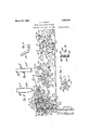
In the' drawings Fig. l1 represents aside elevation of the cigar' bunching machine;
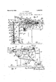
Fia'. 2 is a top plan View of Fig. l; Fig. 3
shows an enlarged section of Fig. 2 on the4 line 3. Fig. `4 is an enlarged section of Fig. `2 on the line 4, 4: Fig. 5 represents an enlarged lett hand side view of Fig. l;
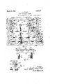
Fig. 6 shows a section on the line 6, 6 of,v
Fig. 3: Fig. 7 shows a section .of Fig.` 1l on j the line 7. 7 Fig. 8 shows an 'elevation of one ot the cams of the machine.; Figs. 91
and l() represent top plan views of collecting chambers of the machine; Fig'. 11 shows :i modified torni o'l vcam with its Aappurtenances and Fig. 12 shows a section on the une i2 of Fig. 11.
The machine comprises the base plate on which are mounted the parallelframes indicated in their entireties by the numerals A and li. The trame A comprises the upper horizontal member 21 which has formed therewith the legs 22. 24 and 25. The leg 24 has toi-med .therewith the journal bearings 2G and 27. rlhe leg 25 has formed therewith tirety by the letter C, and comprises thel YThe operations of the machine automatiside walls and 46. which are connected by the end walls 47 and 48. Lugs 49 are'formed withthe said end walls and are bolted to the frames A and B. .A cylindrical shaped 4receiving pocketl 50 extends between the frames 45 and'46. Guides 51 are formed with the side walls 45 and y46 on the opposite ends of the pocket 50. A suction table 52 withfthe openings 53 extends between the walls 45v and 46 with one end thereo .connected to the receiving pocket 50.. A delivery pocket 54 is formed between the walls 45 and 46 and is connected to the suction table by the inclined connectingA wall 55. Opening lugs 58 and. 59 extend upy from 'the sidel walls 45 and 46. Supportinglegs 61 extendrfrom vthe pocket andare con- 'nectedto the base plate 20. A suetionyfan 62 is supported'on the base plate 20. A suction chamber 63 is fastened to the lower iace of the suction table 52 and isconnected' Ato the` suction i'an by the piping 64.v Ab'ranch lpipe 64.a connects the openings 51.l in -the pocket 50 with the piping 64. Discharge piping 65 leads from the fan 60. i i v Avcollecting chamber is indicated in its entirety by the letterD and comprises the straight front wall 70, the curved rear wall 71, and the straight side wallsv 72, 73. A foot flange 74 at the bottom of the chamber is bolted to the base plate 2O.V A vertical slot 7,5 is formed in the front wall 70. A charging hopper 76 is tormed'with the top open end aoi the said chamber. Journal brackets 77, 78 and 79 are bolted to the front wall 70. A screw 80 is journaled at its top and bottom ends in the journal brackets 79 and 7 7 respectively. A bevel gear 81 is fastened to the lower end of the screw 80. A journal bracket 82 is bolted to the base plate 20.v A sliaft83 is journaled in the journal brackets"'(v 8 and V82 and has fastened to one end thereof the bevel gear 84 which meshes with the bevel gear 8l.
A ratchet wheel 85 isfastened to the other end of the shaft 83.
-A movable curved bottom 88 lis located in the chamber D and has connected thereto the threaded .boss 89 which is in engagement with the screw 80. l
Pairs of journal brackets 90 and 91 are boltedto ythe frontwall 7 0 of the chamberl D.l A shaft 92 is supported in the-brackets 90 and a shaft 93 is supported in the brackets 91.
On the shaft 92 are iastenedone end of each of the similar links 94. To the other ends of said links 94 arel pivoted the links 95 by means of the pivots 96. A shaft 97 is supported in the other ends of the links 95 and a plurality of knife blades 98 are earried on the shaft 97. The said knife blades in one of their positions extend through a `plurality of openings 99 formed in the upper end of the front wall 70. A bracket with the similar side walls 100 and the curved Abottom 101 is fastened to the upper end of .the side walls 72 and 73 of the chamber D and said bottom extends across the width of said chamber. Guide sleeves 105 are fastened to the side walls 72 and 73 of the chamber D.V Guide rods 107 at one are pivoted to the shaft 97 and are guided in the guide sleeves 105 .to maintain the knife `blades 98 in proper operative position.
. Av pair of links 110 have one end each fastened to the shaft 93 and to their other ends are pivoted one end each of the links 111. Apusher 112 is pivoted to the other ends of the links-111. A supporting bracket 113 is fastened4 to the wall 71 of the chamber D for the said pusher 112. A pair of brackets 114 v are fastened to the wall 71 of the chamber D and have each formed therewith a buffer sleeve 115, in each of which is located a Y spring 116. A plunger 117 bears on each ,of
the springs 116, and a triangular 'shaped supporting block 118 with the heel 119 connects `the top ends of the said plungers 117. 'The saidblock 118 normally bears up against the end of the supporting bracket 113.- In the liournal bearings 34 and 42 is supported an oscillating shaft 125 to which latter are fastened'the arms 126 of the presser cover 127 curved on its. lower face with a curvature equal to the curvature of the bottom 88. A link 128 has one end fastened to the shaft 125 and to the other end thereof is pivoted one end of the link 129 by means of the pivot 130.v The other end-of the link 129 is pivoted to a cam to be described by means of the pivot 131.
An oscillating shaft 132 is supported in the bearings 32 and 41 and has fastened thereto at onel end the gear segment 133 which meshes with a gear segment of a cam to be described. A pair of arms 134 have one end each fastened to the shaft 132 and are conf nected at their other ends by the push bar ported on the tracks 145.
Side knife blades 136 are fastened toY the arms 134. An oscillating shaft 140 is ported on the shaft 146. Side openings 149* are formed with the portion 149. A second jaw 151 with therear cylindrical portions 152 and the front cylindrical Vportion 153 has its portions 152 in contact with the shaft 146. Side openings 153a are formed with the portion 153. The vportions 149 and 153 constitute a cigar mould M.
Pairs of opening lugs 154 and 155 are re spectively formed with the . portions 148 and 152. Pairs of spring supporting lugs 156 and 157 are formed with the portions 148 and 152. A segmental cylindrical shaped knife blade 160 bears up against the inner surface of the cylindrical portion 149 and has extending therefrom the guide lug 161 which latter is Aguided in the guide opening 150. A cross pin 1612L extends through the lug l161. A spring 162 has one end fastened to the guide lug 161 and its other end is fastened "to the cylindrical portion 149. Links 166 have the eyelets 167 at one end whichencircle the shaft 146, and at the other ends of the links are formed the eyelets 168.
A cross bracket 169 connects the links 166. A pusher rod 175 with the pusher disc 176 extends through openings in the jaws 147 and 151 and through an opening 177 in theshaft 146. The disc 176 extends the whole length of the mold.vv The rod '175 also extends through an opening in the cross bracket 169. `A spring 178 eneircles the rod 175 and bearsbetween the cross bracket 169 and a pin 179 extending through the rod 17 Two pairs of leaf springs 180 and 181 extend from the cross bracket 169'and bear upon the supporting lngs156 and 157v respectively. rThe springs 180 and 181 normally maintain the jaws 147 and 151 in their closed position. The eyelets 168 engage the shaft 182 and saidvshaft 182 also engages the eyelets 183 at one end of the links 184 and 185. The other ends'186 of the latter linksare fastened to the shaft 187. The'link 184 has formed therewith an extension leg 188 having a journal bearing 189. kJournal brackets 193 are fastened to the frames A. and B and' support the shaft 187. A spur gear 194 is fastened to one end of the shaft 187. A pair of brackets 195 are fastened to the base plate 20 and have supported therein the shaft 196. A link 200 adjacent to the frame B has one end supported on lthe shaft 196 and to its other end is c-onnected a.
' roller 2 01.
A lever E with the arms 205 and 206has Vformed therewith a hub 207 which is sup- Vported on the shaft 196.
- the arm 206 is journaled a roller 211 similar lll),
f to the shaft 235.
A bracket 21.5 is fastened to the base plate 20 adjacent to the frame A and supports the oscillating shaft 216, on one endof which lat-ter is fastened the spur gear 217, and at the other end is fastened the oscillating arm 218 with the ear 219. Thearm 218 has formed at its upper end a guide and supporting cavity 220 for the extension arm 221 having the eyelet end 222. Adjacent to the frame B there is fastened to the 4base plate 20. a bracket 225 similar tof2'15. An oscillating shaft 226 similar to 216 is supported in the bracket 225.v A spur gear 227 similar to 217 is fastened to the shaft 226 at one end thereof. At the other end of the shaft 216 is faste-ned the oscillating arm 228 similar to 2184 and. which has formed therewith an ear 229. The arm 228 has formed at its upper end a guide and supporting cavity 230, for the extension arm 231 similar to the arm 221 and which has formed therewith an eyelet 232 similar to 222. A cross shaft 235 is slidably supported in the eyelets 222 and 232. A roller 236 is fastened A shaft 240 is journaled in the frames A and B as well as in the frames and 46. At the endsy of' the shaft 240 are fastened the grooved pulleys 241. Rubber cords 242 have'one end each connected to the ears 219 and 229 and are then wound around the pulleys 241 and' connected thereto. A canvas apron 245 has one end fastened to the connecting wall 55, is guided over the roller 236 and its other end is wound around the shaft 240 andfastened thereto.
ends of the arms 253 and 254. A plurality of scrapers 260 are fastened to the shaft 255 and are aligned in the clearance spaces be tween the knife blades 98 and the swinging pressers 141. Gn the arm 253 there are secured a plurality of similar pins 262, 263, 264, 265 and 266. Each of the latter pins has formed therewith a head 268 and is secured in place to the arm 253 by means 'of the locking pin 269. A roller 270 is journaled on each of the pins 262 to 266. A cam 275 rides on the roller 270' of the Vpin 262 and is fastened to an arm 276. The end of the arm 276 is fastened tothe shaft 92. A bracket 278 extends up from the base plate 20 and has pivoted in .its top end the arm 279 by means of the pivot 280. At one end of the arm 279 is fastened the cam 281 which engages the roller 270 of the pin 263. The other end of the arm 279 is pivoted t0 the link 129 by means ofthe pivot 131. A
ln the bearing 27k of the frame A is journaled. the driving shaft 310. A spur gear 311 with the grooved cam 312 is fastened to the driving shaft 310. The roller 211 of the arm 206 engages the groove of the cam 312. A spur gear 313 is fastenedto a shaft 314 which latter is journaled in the bearing 26. A pin 315 extends from the spur gear 313 and supports the eyelet 307 of the connecting` rod 306. vA shaft 316 is supported in the bearing 189 of the extension 188 and has journaled thereon the idler spur gear 317. The latter meshes with the spur gears 311 and 313. Journal brackets 320 and 321 are fastened to the base plate 20. A shaft, 322 is journaled in the bracket 320. A cam 325 having formed therewith thegear segment 326 is journaled on the shaft 322. A roller similar to 270 of the'pin 210 rides on the cam 325.l meshes with the gear 217. The coaetion of the `ear segment 326 and the gear 217 0scillates the arm 218. In. the bracket 321 is fastened a shaft 330. A cam 331 having formed therewith a gear segment 332 is journaled on t-he shaft 330. The roller similar to 270 of the pin 201 rides inthe cam 331. The gear segment 332 meshes with the spur gear 227. lThe -coaction of the gear segment 332 and the gear' 227 oscillates the arm 228.
To produce a'cigar bunch thicker in the center than produced with the chamber D having the straight frontwall 70, a chamber Da with the curved front. and rear walls iL and 71 is used. To produce a cylindrical The gear segment 326 cigar bunch a chamber Db with the parallel iront and rear walls 7 Ob and 71b is used.
` Figs.Y 11 and 12 show a modification of the cams. In this instance the cam movements are changed when moving in reverse directions. rlhe cam comprises the body portion 335 in which is formed the main groove 336 that connects with the secondary groove 337. A pivoted stop 338 is normally located in the groove A roller rides in the groovei336 in oneA direction and on its return to its original position rides for a part ot its travel in both of the grooves 336 and 337, as the stop directs the pin into the latter groove.
A plate is bolted to the portion 335 4ot the cam and carries the triangular block 341 which with the said portion 335. forms the grooves ot the cam.
To make the cigar bunches, tobacco which is to constitute the iillers ot the. cigar bunchesis charged into the collecting chainber D. The shat't 310 rotated by means not shown, and through the intervention ot the spur gear 311, idler gear 317. spur gear 313 and the connecting rod 306, the arms 253 and 254 are swung` while the idler gear 317 v is in mesh with the spar gears 311 and 313. lhen the .arm 253 swings in the direction of the arrow G, the kicker 293 cc-ntactswith the arm 299 and therebyv the pawl 300 coacts with the ratchet wheel which turns the shaft 83. The rotati ons ot the shaft 83 through the intervention ot the bevel gears 84- and 81 turns the screw 80. Vithfthe rotations of the screw 80, the bottom 88 of the chamberfD rises and carries up the requisite quantity of tobacco for one bunch at each` cycle ot the` machine. The cam 281 by reason ot its coaction with the roller 27 O on the pin 263 lowers the pres-ser cover 127 and presses the tobacco at the upper opening of the collecting chamber D, while the arms 253 and 254 swing in the direction ot the arrow G (Fig.`1). The cam 275 during the same swing ot the arnis 253 and 254 by reason of the coaction of the roller 270 on the pin 262 and the intervention of the links 94 and 95 has moved the knite blade 98 to the lett in thc direction of the arrow G to clear the top opening` of the collecting Vchamber D@ The arms 253 and' 254 now swine: in a direction opposite to the arrow Gr and the knife bladesf98 cut ott a portion of tobacco through the top ot the opening of the chamber D. Upon the further advance ot the arms 253 and 254 in the direction opposite to the arrow G the scrapers 260 which are fastened to the shaft pnsh the severed portion of the tobacco over the curved bottom 101 into the cavity H. The swinging pressers 141 have been previously swungopen in the direction of the arrow I during the swing of the arm-s 253 and254 in a direction opposite the arrow Gr, by virtue of the coaction of the roller 270 of the pin 266 and the cam 295. The press ers 141 now swing down and bear upon the tobacco in the cavity H during` the end of the swingof the arms and 254 in the direction opposite to the arrow (l. rlhe arms 253 and 254 now swing in the direction of the arrow G and by the coaction of the roller 270 on' the pin 264 and the cam 285, cause the pusher 112 to move to the right in the direction of the arrow K and flforce the.
A135 to bear on the guide lug 161 of the knife blade-160. f The rblade 160 cnts ott the tobacco in the mold M from the tobacco in the cavity H and the blades 136 cut off( the ends of the tobacco that project through the ends ot' the mold M. lVhile the mold M is being .filled with tobacco the disc 176 is pushed back in the direction ot the arrow K (Fig. 3) against the tension of the spring 178. .The arm 291 maintains the supporting block 118 in proper position when the cavity H is being` ,filled with tobacco and. when it is forced out of thesame. At thel proper time p lol) i th'ecoaction of the roller 211 in the grooved camr 312 causes the gear segment 209 to actuate the spur gear 194, which swings the links 184 in the direction of the arrow N, the hinge shaft 1 46 riding on the tracks 145. After the shaft 146 is swung clear of the tracks 145 the links 166 will swing on the shaft 182 and hangl in a vertical position. The idler gear 317 swings with the links 184 and disengages from the spur gears 311 and 313. The cylindrical portions 149 and 153 will now be swung over the receiving pocket 50 and the lugs 153, 155, will contact with the lugs 58 and 59which will open the portions 149 and 153 and the tobacco bunch P will drop upon the apron 245, vand the latter with the apron will be deposited in the pocket 5() as indicated in Fig. 4 in dotted lines. The disc 176 causes the tobacco bunch to be'ejected from the mold M by virtue of the tension of the spring 178. Previously the arms 218 and 228 have been swung to the left as shown in dotted lines in Fig. 4 by the coaction of the gearv segments 326 and 332 Leesava The said suction by means of the branch ipe 64 clears the tobacco of any dust.' Next by the coaction of rollers 210. and 201l with the cams 325 and 331, the arms 218 and 228 are swung to the right in the direction of the arrow Q, which lifts the cigar bunch P out of the pockets 50 and it rolls onthe said leaf S which latter is wound around the bunch P of tobacco. The cams 325 and 331 may be 'of the same or of different curvature i' depending upon whether a cylindrical bunch or a bunch of different shaped endsis to bel formed. 1
Upon the further rotation of the gear 311v the links 184; and their appurtenances swing to the left to cause the idler gear B17 to mesh with the gears 311 and 313 to start a second cycle ofthe machine.
y Various mod'fications may be made in the invention and the present exemplification is to be taken as illustrativeand not limitative thereof. Y
Having described my invention what I desire to secure by Letters Patent and claimis: 1,. In a cigar bunch making machine the combination of a collecting chamber for a charge of tobacco, means to simultaneously compress and discharge the tobacco from one end of the chamber, means to severpredetermined portions of the tobacco after being discharged from the chamber, means to convey Vthe severed portions to a cavity, a mold with hinged portions in the machine, means to compress each severed portion in said cavity and force it into said mold to give it its proper shape, a table in the machine, a. movable apron on the table, means to deposit each shaped severed portionk on the apron and means to roll a binder placed on the apron around each'shaped and severed portion to make bunches for cigars.
2. In a. cigar bunch making` machine the combination of a driving shaft, a collecting chamber open at one end in the machine, a movable bottom in the chamber, means between the driving shaft and said bottom to move the latter, a presser cover swinging over the open end of the collecting chamber, knife bladesswinging over the open end of the chamber, Scrapers moving over the open end of the chamber, the coaction of said elements forcing port-ions of tobacco lout of said chamber, severing said portions and moving the severed portions from the open end of the chamber, means to shape.
said severed portions and means to roll a binder on each severed portion to form a bunch for a cigar.
3. In a cigar bunch making machine the combination of means to compress a charge of tobacco, means to sever portions from said charge, a spring actuated 'plunger in the machine, a movable pusher in the machine coacting with said plunger to com'- press the severed portions of tobacco, an adjustable spring actuated mold coacting with said plunger to open the latter, means todischarge the severed'portions of tobacco from said mold and means toroll a binder on each severed portionrof tobacco after it leaves the' mold.
at. In a cigar bunch making machinev the combination of acollecting chamber toV compressarcharge of tobacco, means to sever portions from said charge, means to coIIP press said severed portions, a moldV with spring actuated portions to shape the severedy portions of. tobacco, a receiving'pocket inthe machine for the severed portions, .a flexible apronoversaid pocket,means to swingsaid mold to deposit the severed portions of tobaccorupon the apron and force saidv apron with said severed portion of tobacco into said pocket, a suction table adjacent to the receiving pocket and covered'by said aprona pair of oscillating shafts under the suction table, an armwith one end fastened to each shaft and a roller journaled in the swinging ends of said arms, said roller contacting with ythe lower face of said apron and adapted to roll said severed portions of tobacco upon said apron over said suction table and roll a leaf of tobacco on each of said severed portions to make bunches for cigars.
5.v In a cigar bnnchmaking machine the combination of a collecting chamber open at one end to compress a charge of tobacco, means to force said charge throughthe open end of the chamber, means to sever portions of said charge as it is discharged from the openendfof the collecting; chambeiya receiving pocket in the machine for the said severedportions, suc-tion means connectedto the pocket, vasuction table adjacent Vto said pocket, a flexible apron over said pocket and table, a mold with flexibly actuated portions adapted lto receive thesevered portions of tobaccoanddeposit them upon the apron intov said pocket, .a-pair of 'shaft-s journaled'under` the suction table, a pair of arms with one end of each fastenedto each shaft and a roller journaled in the swinging ends of said arms, said roller contacting with the lower face of said apron and adaptedv to roll lsaid severed portions of tobacco upon said apron from said pocket over said suction tableand roll a leaf of tobacco on each of said severed portions to make bunches for cigars.
6. In a cigar bunch making machine the cam vand its coacting elements causing the knife blades to reciprocate at predetermined intervals over the open end of said chamber.
28, In a cigar bunch making machine the combination of a collecting chamber open at one end, a presser cover over said open end, an oscillating cam adjacent to said chamber and connecting means between said cam and the presser cover.
9. In a cigar-bunch making machine the combination of a collecting chamber open at one end, a presser cover over said open end, an oscillating arm adjacent to said chamber, a pin on the arm, a cam pivoted adjacent to the oscillating arm with its cam surface coacting with said pin and connecting means between the other end of the cam vand said presser cover.
10. In a cigar bunch making machine the combination of a collecting chamber open at one end, an. oscillating arm adjacent to said chamber, a pin on said arm, a cam pivoted adjacent to said chamber with its cam surface coacting with said pin, an oscillating shaft supported adjacent to lthe chamber, a link with one end fastened to the shaft, a second link connecting the first link and the said cam and a presser cover over the chamber With one end fastened to said shaft.
11. In a cigar bunch making machine the combination of a pusher slidably supported, a shaft journaled below the pusher, an oscillating'arm in the machine, a pin extending from the arm, a cam with `one end fastened t0 the shaft and Aits cam surface coacting with the pinand linked connections betwecz'i the -shaft and pusher to reciprocate thelatter. Y v 1 l2. In a cigar bunch making machine the combination of a mold for a material, a knife blade for the mold to cut the material throughout the length thereof and a pair of knife blades to cut the material at the ends of the mold, an oscillating cam in the machine and connecting means between the cam and the knife blades. l
13. In a cigar bunch making machine the combination of a mold fora material, angoscillating arm in the machine, a pin on the arm, a cam pivoted in the machine With its cam surface coacting with the pin, a gear segment formed with the cam, a shaft journaled in the machine, a gear segment fas- Vtenecl'to the-shaft meshing with the first gear segmentfa pair of arms with one end of each fastened to the shaft, a knife blade fastened to each arm, a pusher bar connecting the arms, a knife blade in thc mold and a guide lug extending from the latter knife blade in the path of the pusher bar, the coaction ofv the elements actuating the knife blade in the mold to cut the material throughoutthe lengt-l1 of the mold and the knife blades on the arms cutting the material atthe ends of the mold. 1
14. In a cigar bunch making machine the combination of a shaft journaled therein, swinging pressers fastened to the shaft, an oscillating ar'm in t-he machine, a pin eX- tending from the arm and a cam with Vone end fastened to the shaft and its camk surface coacting with lsaid pin, the oscillations of the arm ycausing the swinging pressers to actuate through the intervention of the intervening elements.
In testimony whereof I affix my signature.
JosEPH LEOPOLD PoLDY.
Priority Applications (1)
| Application Number | Priority Date | Filing Date | Title |
|---|---|---|---|
| US109804A US1663174A (en) | 1926-05-17 | 1926-05-17 | Cigar-bunch-making machine |
Applications Claiming Priority (1)
| Application Number | Priority Date | Filing Date | Title |
|---|---|---|---|
| US109804A US1663174A (en) | 1926-05-17 | 1926-05-17 | Cigar-bunch-making machine |
Publications (1)
| Publication Number | Publication Date |
|---|---|
| US1663174A true US1663174A (en) | 1928-03-20 |
Family
ID=22329652
Family Applications (1)
| Application Number | Title | Priority Date | Filing Date |
|---|---|---|---|
| US109804A Expired - Lifetime US1663174A (en) | 1926-05-17 | 1926-05-17 | Cigar-bunch-making machine |
Country Status (1)
| Country | Link |
|---|---|
| US (1) | US1663174A (en) |
-
1926
- 1926-05-17 US US109804A patent/US1663174A/en not_active Expired - Lifetime
Similar Documents
| Publication | Publication Date | Title |
|---|---|---|
| US1663174A (en) | Cigar-bunch-making machine | |
| US1799128A (en) | Cigar blending and bunching machine | |
| US587828A (en) | District | |
| US1981469A (en) | Cigar bunch forming | |
| US1077886A (en) | Cigar-machine. | |
| US842618A (en) | Cigar-bunching machine. | |
| US2276962A (en) | Cigar machine | |
| US983480A (en) | Machine for making cigarettes. | |
| US504768A (en) | L williams | |
| US974453A (en) | Wrapping-machine. | |
| US1191199A (en) | Cigar-bunch shaper. | |
| US1128989A (en) | Cigar-machine. | |
| US851681A (en) | Cigar-machine. | |
| US416911A (en) | Machine | |
| US514238A (en) | Cig-arette machine | |
| US1075172A (en) | Cigar-machine. | |
| US1634690A (en) | Cigar-bunching machine | |
| US1528482A (en) | Machine for forming cigar bunches | |
| US809410A (en) | Machine for the manufacture of cigars, cigarettes, cigar-fillers, and the like. | |
| US1502403A (en) | Cigar-bunch machine | |
| US1801231A (en) | Art of cigar manufacture | |
| US612872A (en) | Teenths to peter h | |
| US422000A (en) | Cigar-bunching machine | |
| US1672503A (en) | Scrap-bunch machine | |
| US355968A (en) | bonsack |