US1663169A - Toy vehicle - Google Patents
Toy vehicle Download PDFInfo
- Publication number
- US1663169A US1663169A US178530A US17853027A US1663169A US 1663169 A US1663169 A US 1663169A US 178530 A US178530 A US 178530A US 17853027 A US17853027 A US 17853027A US 1663169 A US1663169 A US 1663169A
- Authority
- US
- United States
- Prior art keywords
- axle
- vehicle
- toy
- motor
- wheels
- Prior art date
- Legal status (The legal status is an assumption and is not a legal conclusion. Google has not performed a legal analysis and makes no representation as to the accuracy of the status listed.)
- Expired - Lifetime
Links
Images
Classifications
-
- A—HUMAN NECESSITIES
- A63—SPORTS; GAMES; AMUSEMENTS
- A63H—TOYS, e.g. TOPS, DOLLS, HOOPS OR BUILDING BLOCKS
- A63H29/00—Drive mechanisms for toys in general
- A63H29/02—Clockwork mechanisms
- A63H29/06—Other elements therefor
Description
March 20, 1928. I 1,663,169
' L- MARX TOY VEHICLE Filed March 2 1927 INVENTOR Louis Marx Patented Mar. 20, 1928.
nours'manx, or BROOKLYN, NEW roan.
If 'roY vnnrcnn.
Application filed March 26; 1927. Serial N0.1178,530.
"This invention relates to a toy, and relates more :particularly to motor driven vehicle toys; :andhas special reference to .the pro- -visipnof a-.vehicle;toy which is adapted to bepropelled in an amusingly erratic manner.
The .prime object. of, my present invention relatesto amotor driven toy simulating an automotive vehicle embodying a drive mechanism constructed and designed to propel :thei'toy along the-ground or other suitable supportawith a rollicking .oroscillating side to side motion combined with a skip and .start skidding action producing a non-uniiformaand changeable erratic behaviour in the propulsion of the toy.
' :Other'principal objects of the invention reside in the provision of an erratically op- .eratedevehicle in which the vparts are con- 0 structed with standard'vehicle parts organizedtso asto be operated by such standard parts inadurable and efiicient manner producing 1a constructionwhich may be manufactured at low cost and sold at a low figure. 6
Toathe accomplishment of the foregoing and vsuch other objects as will hereinafter appear, my invention consists in the elements and their-relation one to the other, ashereiinafter more particularly described and soughtato be defined in the claims; reference being ;had -to the accompanying drawings mWhlCll .show the preferred embodiment of :myvinvention, and in which:
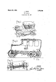
Fig. 1- is a perspective View of the vehicle .ioyof my invention,
Fig. 2 is a longitudinal cross-sectional .view thereof drawn to an enlarged scale, and
Fig.3. is a'fragmentary view thereof taken .in cross-section in the plane of the line 3-3, Fig. 2.
Referring-now more in detail to the drawings,-the toy vehicle embodying my invention comprises a vehicle body generally designated as A, shaped to simulate anautomotive body, and a motor mechanism B constructed and designed to impart to the body A an erratic and amusing propelling action -When-the toy is set in operation.
The vehicle body A, preferably having a design of a well known commercial make :of vehicle body, is fashioned from sheet metal, the parts of which are assembled together in any ,manner well known [to the toy .art. In said body A ,are journalled front and rear axles 10 and ,11 respectively, which axles are given; a. uniqueend configuration for the purpose of impartingithe erratic behaviour to the vehicle in the propulsion thereof; and to, accommodate the ready reception of these ,axles ,by the vehicle body in the assembling of the parts, the side walls 12and 13 of the body A are provided-with open ended journallingslots 14,,11, the en- 05 trantmcnds of which slots are substantially narrower than the axle seating portions thereof. NV-iththisconstruction it will-be apparent that the axles may be seated in the j ournalling side walls of the vehicle body by insertingthevsaine through the receiving slots l4, l4. One of the sides of the front axle 10 is journalled in theside wall 12 of the body in ainanner similar ,to that described for theaxle 11; butthe other side of said axle 10 is journalled in the side wall .13 of the body in the manner best ,ClGPIClZGCl lniFig. 2- Ofj the drawings, saidside iwallbeing provided with a slot 15.having a pluralityof recessed portions..16 therein in which the axle "1 0 isv adapted to beselec- .vtively seatedifor steering purposes, the said axle VIObeingEheld in any of its adjusted positions by meansyofa spring element '17 bearing against the axle and anchored to: the ,body wall 13 asat 18. Preferably also, the said ,body A is provided .with a bracing member 19 in the form of a seat which may carry a chauffeur or other driving'figure20. i
The motor mechanism "B comprises a spring motor construction of well known form mounted within the body A and connected to drive the rear driving axle .11, the saidniotormechanism comprisinga drum 95, 2l to one end of which is fixed a torsion spring 22, the said drum carrying a gear 23 meshing with a pinion24 fixed to a shaft 25 which shaft carries a gear 26 meshing-in turn with'a pinion 27 fixed to the drive axle =11. 1 For winding the motor mechanism there is provided the usual winding key 28 having a shaft 29 extending'through the drum 21, and to said shaft is fixed a ratchet wheel 30 cooperating witha stop pawl 31. With this construction, as is well known to those skilled in the art, when the winding key 28 is turned, the motor will be energized to impart motion to the drive axle l1.
As heretofore mentioned, the desired object of the invention resides in the provision at their centers with a loose fit. More specifically, as shown in the drawings, the drive axle 11 is provided at its opposite ends with the crank sections 32 and 33 disposed in opposite directions so that the offset portions 34c'and 35 are arranged on opposite sides of the axis of the axle 11; and onthese offset portions 34 and 55 the traction wheels 36 and37 are mounted with a loose fit so that the wheels are freely rotatable on the axle ends. Similarly, the front axle 10 is pro vided with oppositely disposed cranked sections 38 and 39 on which are loosely mounted the front traction wheels 40 and 421.
The operation of the vehicle toy of my invention will be readily understood. When the motor me'chanism is energized and the toy vehicle set or placed upon the ground or other suitable support the drive wheel 11 will be rotated to impart motion to the crank ends 32 and 33 thereof, the operation of which may or may not impart propelling motion to the toy depending upon the degree of energization of the motor, the frictionbetween the wheels and the support and the momentum of the toy, as well as upon other operating features. Accordingly, the
. toy atone time will be made to oscillate from side to side with a wheel skidding action I without any forward propulsion imparted to the vehicle, while at another time the vehicle will be propelled with a skipping and "starting behaviour which may be described as by fits and spurts, while the vehicle The to varying the side to side oscillation so that at one time the toy body may be bodily oscillated from side to side while at another'time such oscillation is transformed into a gymtory action with all parts of the vehicle moving up and down at different times. Thus a varymg erratic action is effected which affords considerable amusement. r
It will also be apparent that while I have shown and described my invention in the preferred, form, many changes and modifica- To accomplish these results, and;
motor means supported on said body and connected to said axle to drive the same, at leastone of the ends of said axle being provided with an integral crank section having a wheel receiving'portion offset from the axis of said axle, and wheels loosely mount.- ed 'at their centers onsaid axle, one of-said wheels being mounted upon the'olfset-por- 7 tion of thecra-nkend of said axle whereby upon energization of said motor the vehicle maybe propelled with a skip andstartTaction combined with a sideto side oscillating or rollicking motion. j
2. A motor driven toy vehicle comprising l avehicle body. andmeans for propelling the same in an erraticmanner, said means comprising a drive axle journalled insaid body, motor means supported on said bodyand connected to'said axle-to drive the'same, the opposite ends of said axle being provided with oppositely disposed integral gcra-nk sections having wheel receiving portions offset from the axis of said axle, and wheels loosely mounted at their centers on the offset. portions of the crank endsof said axle whereby upon energization of said motor the vehicle may be propelled with a skip andstart acor rollickingmotion. V
A motor driven :vehicle comprising a vehicle body shaped to simulate an automotive vehicle. and means for propelling the same in an erratic manner, said means comtion combined with. a side to side oscillating lprising afront axle and a rear drive axle journalled in i said body, 1a" spring -motor 'means-supported within said body and providedwith gearing connected to said drive axle, the opposite ends of each'of said axles being provided with oppositely disposed integral crank sections having wheel receiving portions olfsetfrom the-axes of said axles, the front-axle being loosely journalled in said body, and wheels loosely mounted at their centers on the offset portions'of all thecrank ends of said axles whereby. "upon energization of said motor the vehicle may be propelled with a skip and .start skidding action combined with an erratic side to, side oscillating or rollicking motion.
4. A motor driven toy vehicle comprising avehicle body and means for propelling the same in an erratic manner, said means comprising a drive axle journalledin saidbody',
motor means supported onsaid body and connected to said axle to drive the same, at least one of the ends of said axle being provided with an integral crank section having a wheel receiving portion oifset from the axis of said axle, and wheels mounted at their centers on said axle, one of said wheels being mounted upon the offset portion of the crank end of said axle and at least one of said wheels being loosely mounted on said axle whereby upon energization of said motor the skip and start motion.
Signed at New York, in the county of New York and State of New York this 23rd day of March A. D. 1927.
LOUIS MARX.
Priority Applications (1)
| Application Number | Priority Date | Filing Date | Title |
|---|---|---|---|
| US178530A US1663169A (en) | 1927-03-26 | 1927-03-26 | Toy vehicle |
Applications Claiming Priority (1)
| Application Number | Priority Date | Filing Date | Title |
|---|---|---|---|
| US178530A US1663169A (en) | 1927-03-26 | 1927-03-26 | Toy vehicle |
Publications (1)
| Publication Number | Publication Date |
|---|---|
| US1663169A true US1663169A (en) | 1928-03-20 |
Family
ID=22652903
Family Applications (1)
| Application Number | Title | Priority Date | Filing Date |
|---|---|---|---|
| US178530A Expired - Lifetime US1663169A (en) | 1927-03-26 | 1927-03-26 | Toy vehicle |
Country Status (1)
| Country | Link |
|---|---|
| US (1) | US1663169A (en) |
Cited By (3)
| Publication number | Priority date | Publication date | Assignee | Title |
|---|---|---|---|---|
| DE1275426B (en) * | 1961-12-23 | 1968-08-14 | Schreyer & Co | Car vehicle toys |
| US5288262A (en) * | 1991-12-13 | 1994-02-22 | Phillips E Lakin | Crazy wheels toy |
| US20050090180A1 (en) * | 2003-10-24 | 2005-04-28 | Tomy Company, Ltd. | Multi-axle running toy and multi-axle running toy set |
-
1927
- 1927-03-26 US US178530A patent/US1663169A/en not_active Expired - Lifetime
Cited By (4)
| Publication number | Priority date | Publication date | Assignee | Title |
|---|---|---|---|---|
| DE1275426B (en) * | 1961-12-23 | 1968-08-14 | Schreyer & Co | Car vehicle toys |
| US5288262A (en) * | 1991-12-13 | 1994-02-22 | Phillips E Lakin | Crazy wheels toy |
| US20050090180A1 (en) * | 2003-10-24 | 2005-04-28 | Tomy Company, Ltd. | Multi-axle running toy and multi-axle running toy set |
| US7329167B2 (en) * | 2003-10-24 | 2008-02-12 | Tomy Company, Ltd. | Multi-axle running toy and multi-axle running toy set |
Similar Documents
| Publication | Publication Date | Title |
|---|---|---|
| US3331463A (en) | Motor operated ambulatory vehicle | |
| US1663169A (en) | Toy vehicle | |
| US3919804A (en) | Traveling toy | |
| GB1155473A (en) | Dismountable Moving Toy | |
| US3659378A (en) | Motor driven toy vehicles | |
| US3101569A (en) | Remote electrically controlled wheeled toy | |
| US4463520A (en) | Self-returning toy vehicle | |
| US3940879A (en) | Walking doll | |
| US2567453A (en) | Pumpmobile toy | |
| US1872289A (en) | Toy vehicle | |
| US1821940A (en) | Traveling wheeled gyroscopic toy | |
| US3192664A (en) | Toy vehicle | |
| US1420597A (en) | Toy | |
| US3720016A (en) | Toy having slotted axle and elastic strip drive means laterally insertable therethrough | |
| US1646169A (en) | Toy automobile | |
| US1643918A (en) | Toy steamboat | |
| US1418817A (en) | Child's occupant-propelled vehicle | |
| US2549980A (en) | Toy handcar | |
| US6568987B1 (en) | Brake assembly for a toy vehicle | |
| US1610568A (en) | Figure wheeled toy | |
| US1670060A (en) | Animated toy | |
| US425612A (en) | Dersfield | |
| US1410429A (en) | Mechanical toy | |
| US1705681A (en) | Manually-propelled vehicle for children | |
| US1334544A (en) | Toy dump-wagon |