US1663161A - Adjustable deflector - Google Patents
Adjustable deflector Download PDFInfo
- Publication number
- US1663161A US1663161A US1663161DA US1663161A US 1663161 A US1663161 A US 1663161A US 1663161D A US1663161D A US 1663161DA US 1663161 A US1663161 A US 1663161A
- Authority
- US
- United States
- Prior art keywords
- arm
- flange
- adjustable
- deflector
- flanges
- Prior art date
- Legal status (The legal status is an assumption and is not a legal conclusion. Google has not performed a legal analysis and makes no representation as to the accuracy of the status listed.)
- Expired - Lifetime
Links
- 239000000945 filler Substances 0.000 description 7
- 238000010276 construction Methods 0.000 description 3
- 235000017414 Canapa Nutrition 0.000 description 1
- 244000200747 Canapa Species 0.000 description 1
- CRQQGFGUEAVUIL-UHFFFAOYSA-N chlorothalonil Chemical compound ClC1=C(Cl)C(C#N)=C(Cl)C(C#N)=C1Cl CRQQGFGUEAVUIL-UHFFFAOYSA-N 0.000 description 1
- 235000000396 iron Nutrition 0.000 description 1
- 238000009877 rendering Methods 0.000 description 1
- 230000000717 retained effect Effects 0.000 description 1
- 239000004460 silage Substances 0.000 description 1
Images
Classifications
-
- B—PERFORMING OPERATIONS; TRANSPORTING
- B65—CONVEYING; PACKING; STORING; HANDLING THIN OR FILAMENTARY MATERIAL
- B65G—TRANSPORT OR STORAGE DEVICES, e.g. CONVEYORS FOR LOADING OR TIPPING, SHOP CONVEYOR SYSTEMS OR PNEUMATIC TUBE CONVEYORS
- B65G53/00—Conveying materials in bulk through troughs, pipes or tubes by floating the materials or by flow of gas, liquid or foam
- B65G53/34—Details
- B65G53/60—Devices for separating the materials from propellant gas
Definitions
- the object of my presentinvention is'the provision of a peculiarand vadvantageous adjustable deflector for silo fillers; and it :consistsfin the improvement hereinafter .de-
- Figure 3 is an enlarged transverse section v takenon the plane indicated by the line 3-3 of Figure 2, lookingetoward the right.
- Figure 4 is an enlarged detail view illustrating the arrangement of vthe adjustable Vsection of my novel deflector vwith its forward end flush with Athe forward end of the major member of the deflector. Similarnumerals,designate corresponding parts in all the viewsofthe drawing.
- I show in Figure 2 a filler'pipe 2 with a circumferential ange- 3, and also with a tubular portion 4 extending va considerable distance above thev circumferential flange, the said portion 4 being designed to counteract any lateral strain onfthe connection of the major member 5 of myimprovement to the filler pipe 2.
- the major member 5 is provided with a vertical tubular portion 6 which surrounds and is turnable about the tubular portion 4 and is provided at its lower'end with a flange 7, superposed upon the beforementioned flange 3.
- the said fiange 7 is retained on the fiange 3 through the medium of a iianged annulus 8 and bolts 9 connecting the annulus 8 to the flange 3, and surrounding the flange 7 so as not to interfere with the movement of the same about the pipe portion 4 and on the flange 3.
- the major member 5 of my deflector is strongly connected to the filler pipe 2, and yet said member 5 is adapted to be turned about the pipe 2 as a center, and this without the imposition of strain on the connection described between the filler pipe 2 and the member 5.
- the major member 5 includesv an overhanging arm 10 extending upwardly and laterally relative to the tubular portion 6.
- the said arm 10 includes a curved wall 11 and skirt flanges l2 extending at right angles tothe side edges ofthe wall 1,- Figures 2 and 3.
- the J ⁇ side flanges 12 are tapered or gradually reduced in width forwardly, and it will also be noted that the said flanges 12 extend a considerable distance beyond the wall .11 for the ⁇ purpose hereinafter pointed out.
- the arm 10 is provided at opposite sides with fianges 13, the said flanges 13 being of the length indicated by dotted lines in Figure 2 and being preferably comprised of angle irons iixedly connected to opposite sides of the arm 10.
- a bifurcatedlug 14 At the back of the upper end of the tubular portion 6 comprised inthe major member 5 is a bifurcatedlug 14, Figures 1 and 2, the said lug being to receive and engage links of a chain 15.
- theV arm'lO and the majorrmember 5 Vis provided at oppo Asite' sides with abutments 16, preferably in
- my improvement comprises a longitudinally curvilinear endwise adjustable member 18.
- the said member 18 is provided with side channelportions 19 receiving the flanges 13 of the arm 10, and consequently it will be manifest that the member 18 is free to be moved lengthwise on the arm 10.
- the channel portions 19 of the member 18 are provided with pins, designed and adapted to bring up against the stop 16 on the arm 10 and thereby limit the forward movement of the member 18 and prevent disconnection of said member 18 from the arm 10.
- the before mentioned chain 15 is connected at 21 to the heel portion of the member 18, and hence it will be manifest that the chain 15 may be used for the retraction of the member 18 and may also be used to prevent casual forward movement of the member 18 beyond certain positions in which it is placed.
- a handle 22 is provided on the rear portion of the member 18 to facilitate endwise adjustmentof the said member 18, and when deemed expedient, the member 18 may be provided on its forward portion with a hook 23.
- the member 18 is provided with shoes designed and adapted to rest and move against the. inner side of the skirt anges l2 with 'View to rendering easy the l endwise movement of "the member 18 and at the same time prevent 'lateralhplay- Y of the member 18 on thevarmrlO.
- piperand alsov having a curvilinear arm iivithlfa" curved back Wall and With skirtyianges extending therefrom, said skirt flanges extending ⁇ a considerable distance befl Y yond ⁇ the forward'end of said curvedvall, an Y annul'ussuperposed on the ⁇ flange of saidf de- Hector member,4 and also superposedon the flange of tlielill'ei pipe and "connected to the latter Hanger, and a ⁇ ,curvilinear extensible A member mounted lon the said arm or' theifdeflector, and adapted ivhenretifacted topermit )otensilagevbeingf sliotfbetween.
Landscapes
- Engineering & Computer Science (AREA)
- Mechanical Engineering (AREA)
- Agricultural Chemicals And Associated Chemicals (AREA)
Description
Inventor "/IVIIIIIIIIIIIHA'IIHQI",
W. C. FABER ADJUSTABLE DEFLECTOR FOR SILO FILLERS Filed FebLZS, 1927 March 2o, 192s.
l /l I l [lll l l l llllllllll Patented Mar. 2o, 192s.y
canapa,
p. winpiainlc- FABER? or Lnewnew, InLINoIs. 'Y
' ADJUSTABLE partner-on son sino nrLLnRs.
f Appncatin flied February as, 1927. lserial no. 170,275.
The object of my presentinvention is'the provision of a peculiarand vadvantageous adjustable deflector for silo fillers; and it :consistsfin the improvement hereinafter .de-
6 scribed and definitely claimed.
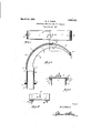
In the` accom lanyingI'drawing, forming lpart of this specification-zj Figure 1 is atop plan-view of the deilector construction'constituting the preferred embodiment of my invention.O Figure 2-is a vertical section of the same.
Figure 3 is an enlarged transverse section v takenon the plane indicated by the line 3-3 ofFigure 2, lookingetoward the right. l Figure 4 is an enlarged detail view illustrating the arrangement of vthe adjustable Vsection of my novel deflector vwith its forward end flush with Athe forward end of the major member of the deflector. Similarnumerals,designate corresponding parts in all the viewsofthe drawing. I show in Figure 2 a filler'pipe 2 with a circumferential ange- 3, and also with a tubular portion 4 extending va considerable distance above thev circumferential flange, the said portion 4 being designed to counteract any lateral strain onfthe connection of the major member 5 of myimprovement to the filler pipe 2. I
As clearly illustrated in "Figure 2 the major member 5 is provided with a vertical tubular portion 6 which surrounds and is turnable about the tubular portion 4 and is provided at its lower'end with a flange 7, superposed upon the beforementioned flange 3. The said fiange 7 is retained on the fiange 3 through the medium of a iianged annulus 8 and bolts 9 connecting the annulus 8 to the flange 3, and surrounding the flange 7 so as not to interfere with the movement of the same about the pipe portion 4 and on the flange 3. By virtue of this construction, the major member 5 of my deflector is strongly connected to the filler pipe 2, and yet said member 5 is adapted to be turned about the pipe 2 as a center, and this without the imposition of strain on the connection described between the filler pipe 2 and the member 5. 50 In addition to the upright tubular portion 6 referred to, the major member 5 includesv an overhanging arm 10 extending upwardly and laterally relative to the tubular portion 6. V
The said arm 10 includes a curved wall 11 and skirt flanges l2 extending at right angles tothe side edges ofthe wall 1,-Figures 2 and 3. As will be notedfrom Figure 2, the J` side flanges 12 are tapered or gradually reduced in width forwardly, and it will also be noted that the said flanges 12 extend a considerable distance beyond the wall .11 for the `purpose hereinafter pointed out. The arm 10 is provided at opposite sides with fianges 13, the said flanges 13 being of the length indicated by dotted lines in Figure 2 and being preferably comprised of angle irons iixedly connected to opposite sides of the arm 10. At the back of the upper end of the tubular portion 6 comprised inthe major member 5 is a bifurcatedlug 14, Figures 1 and 2, the said lug being to receive and engage links of a chain 15. Y By comparison of Figures 2 and3, it will further be understood that theV arm'lO and the majorrmember 5 Vis provided at oppo Asite' sides with abutments 16, preferably in In addition to the elements named, my improvement comprises a longitudinally curvilinear endwise adjustable member 18. The said member 18 is provided with side channelportions 19 receiving the flanges 13 of the arm 10, and consequently it will be manifest that the member 18 is free to be moved lengthwise on the arm 10. At 20 the channel portions 19 of the member 18 are provided with pins, designed and adapted to bring up against the stop 16 on the arm 10 and thereby limit the forward movement of the member 18 and prevent disconnection of said member 18 from the arm 10. The before mentioned chain 15 is connected at 21 to the heel portion of the member 18, and hence it will be manifest that the chain 15 may be used for the retraction of the member 18 and may also be used to prevent casual forward movement of the member 18 beyond certain positions in which it is placed. A handle 22 is provided on the rear portion of the member 18 to facilitate endwise adjustmentof the said member 18, and when deemed expedient, the member 18 may be provided on its forward portion with a hook 23. At 24, Figures 2 and 4, the member 18 is provided with shoes designed and adapted to rest and move against the. inner side of the skirt anges l2 with 'View to rendering easy the l endwise movement of "the member 18 and at the same time prevent 'lateralhplay- Y of the member 18 on thevarmrlO.
In the practical use of my improvement,`
When a silo is `filled to Within about ten .feet of the top7 one man can sitthei'e and operate my novel delector, an d in thatgivay dis?Y tribute the silage Where it is desired, and 1n 2=all oditheispace withinfthe Wall ofthe silo eanfbe, covered,r j
In addition to f. the f practical advantages Yaseiffibedo l,my improvements, it will be @ap- :preeiated that the preferred embodiment of my inventienv-iis simple; and inexpensive -in construction-iand/atthe same time .is durable anvdgtliereOr-e -Well adaptedito withstand the usagetdavhicli devices of coi-'responding yharacter: aresordinarily subjected.
I have explicitly described the preferred embedimentlof myfinvention in ordersto impartfaniinderstanding of the said embodiment? in:allyoiiitsfdetails.. Ido notqdesire, however5 to i be understood as limiting myself toithe v,-piiecise construction"shown, my inventipnlbeing defined f; by my Y' appended lclaims Witlii-rgtlieseope of which modications may be made without departure `from my invention u Hav-img thiisdescribed the Vinventiom what I. :claim is :1
l. In combination/,asilo ller pipe ,having *i a circumferential yflange at an intermediate pointvfand also havinga tubular yportion extending abovevsaid flange, a deeetor` ineinbei'w havingl a tubular portion surrounding` saidutubnlai; portion of the ller pipe and Y 'flangedatits lower end to bear on the flange i of the fille-r.. piperand alsov having a curvilinear arm iivithlfa" curved back Wall and With skirtyianges extending therefrom, said skirt flanges extending` a considerable distance befl Y yond` the forward'end of said curvedvall, an Y annul'ussuperposed on the `flange of saidf de- Hector member,4 and also superposedon the flange of tlielill'ei pipe and "connected to the latter Hanger, and a `,curvilinear extensible A member mounted lon the said arm or' theifdeflector, and adapted ivhenretifacted topermit )otensilagevbeingf sliotfbetween. the forward portionslof the skirt r.flanges-of lthe arm; the said arm--oi-the v-'deflector being provided Withqside angesfand the .lsaidend- Wise if adjustable v curvilinear I member-v being providedpwth "channel portions receiving said Hangeso tbe-armi-.an'd the arrnqbeingV .previdedfwith -stopmeans,-and theflendwise v i adjustable curvilineary member ybeging.; gprovided; ivithmeans to bring .up `lagainstsaid Shopmeans@v 4, Y f f 2. In an adjiista-ble deflectorfor silo fillers,
andfin coiiyliination;Lay curvilinearrarm--haw ing a baek--vvalhand skirt ilflanges, and-also having its skirt flanges extendedV riconsider-v ablef@distanceF beyond. .its-curvilinear baek Wall7l and, a rigidfcuiiviline'ar lengthwise: slidably? djiustableilmemlierf engaged: with: `and f adjustable {bodily}Y env-the. said Aarm, and
adapted--iwhenyretractedyto permit offensif' lage being shot between thev forwardipertions of the skirt anges. i f
WILLIAMQG; FABER
Publications (1)
| Publication Number | Publication Date |
|---|---|
| US1663161A true US1663161A (en) | 1928-03-20 |
Family
ID=3414724
Family Applications (1)
| Application Number | Title | Priority Date | Filing Date |
|---|---|---|---|
| US1663161D Expired - Lifetime US1663161A (en) | Adjustable deflector |
Country Status (1)
| Country | Link |
|---|---|
| US (1) | US1663161A (en) |
Cited By (2)
| Publication number | Priority date | Publication date | Assignee | Title |
|---|---|---|---|---|
| US2705597A (en) * | 1952-02-13 | 1955-04-05 | Viking Mfg Company | Portable grinding mills |
| US4286530A (en) * | 1979-07-26 | 1981-09-01 | Conley Richard L | Multiple row seed planter with common seed storage |
-
0
- US US1663161D patent/US1663161A/en not_active Expired - Lifetime
Cited By (2)
| Publication number | Priority date | Publication date | Assignee | Title |
|---|---|---|---|---|
| US2705597A (en) * | 1952-02-13 | 1955-04-05 | Viking Mfg Company | Portable grinding mills |
| US4286530A (en) * | 1979-07-26 | 1981-09-01 | Conley Richard L | Multiple row seed planter with common seed storage |
Similar Documents
| Publication | Publication Date | Title |
|---|---|---|
| US1663161A (en) | Adjustable deflector | |
| US2973224A (en) | Wheelbarrow | |
| US2258932A (en) | Agricultural implement | |
| US3220489A (en) | Cultivator sweep assembly | |
| US2486483A (en) | Folding drawbar for sectional harrows | |
| US1821305A (en) | Flashlight support and bracket therefor | |
| US1849411A (en) | Method of extinguishing grass and similar fires | |
| US1715613A (en) | Rake attachment | |
| US2136354A (en) | Foldable stool | |
| US2211759A (en) | Shut-off connection | |
| US1967379A (en) | Trailbuilder bowl for wheeled vehicles | |
| US1442270A (en) | Toilet-seat front shield | |
| US1372599A (en) | Tripod for machine-guns | |
| US1919365A (en) | Fire-fighting equipment | |
| US1703282A (en) | Ironing board | |
| US1488825A (en) | Back rest for seats | |
| US992972A (en) | Grain-scoop. | |
| US2347065A (en) | Stepladder | |
| US2299629A (en) | Hose jack | |
| US1619668A (en) | Toy navigator | |
| US3069792A (en) | Tractor terrace blade with load accommodating means | |
| US1412347A (en) | Combined road grader and scraper | |
| US1628782A (en) | Snow shovel | |
| US1829092A (en) | Vehicle tongue coupling | |
| US2082536A (en) | Rail car |