US166315A - Improvement in photographic cameras - Google Patents
Improvement in photographic cameras Download PDFInfo
- Publication number
- US166315A US166315A US166315DA US166315A US 166315 A US166315 A US 166315A US 166315D A US166315D A US 166315DA US 166315 A US166315 A US 166315A
- Authority
- US
- United States
- Prior art keywords
- camera
- box
- improvement
- back part
- photographic cameras
- Prior art date
- Legal status (The legal status is an assumption and is not a legal conclusion. Google has not performed a legal analysis and makes no representation as to the accuracy of the status listed.)
- Expired - Lifetime
Links
Images
Classifications
-
- G—PHYSICS
- G03—PHOTOGRAPHY; CINEMATOGRAPHY; ANALOGOUS TECHNIQUES USING WAVES OTHER THAN OPTICAL WAVES; ELECTROGRAPHY; HOLOGRAPHY
- G03B—APPARATUS OR ARRANGEMENTS FOR TAKING PHOTOGRAPHS OR FOR PROJECTING OR VIEWING THEM; APPARATUS OR ARRANGEMENTS EMPLOYING ANALOGOUS TECHNIQUES USING WAVES OTHER THAN OPTICAL WAVES; ACCESSORIES THEREFOR
- G03B13/00—Viewfinders; Focusing aids for cameras; Means for focusing for cameras; Autofocus systems for cameras
- G03B13/32—Means for focusing
- G03B13/34—Power focusing
- G03B13/36—Autofocus systems
Definitions
- the nature oi'our improvement consistsin the manner of adjusting the swingingof the entire buck part of the camera-box by means 0i' the screw E, which allows and enables the operator to bring the entire back part of the camera-box in any desired position.
- Figure I is the ground plan.
- Figs. II and V represent the side elevations.
- Fig. III represents the front ot' the camera-box.
- Fig. IV represents the plate-holder when the slides are drawn out on both sides.
- A is the bed of the camerabox.
- B is the bed-plate or the way on which the camera-box is made to move.
- C is the hinge fastened to the bed-plute, and connecting the same with the entire back part oi' the camera-box.
- D D represent the views of the entire back part of the camera-box.
- E E is the screw on the side of the camera for swinging the entire back part of' the camera-box.
- F is the set-screw on the back part of the camera-box, running in a slot, which, when set, keeps the back part of the camera-box permanently iu a steady position.
- G, Fig. II represents the side elevation of the front part of the camerabox, with the shifting front H. H, Fig.
- III is the front elevation ofthe camera-box, with the slides H drawn out, as marked by points.
- I, Fig. IV, is a view of the plate-holder, with the slides I of the plateholder when drawn out on both sides.
- v K is the plate-holder attached to the camera-box.
- L is the bcusingscrew.
- M is the die-frame.
- the head of the picture will be kept more in the proper position, and the operator will not find any diiiiculty at all in sct ting all the other parts of the picture in the exactly required line.
Landscapes
- Physics & Mathematics (AREA)
- General Physics & Mathematics (AREA)
- Accessories Of Cameras (AREA)
Description
l. & 1 STUCK ZSheets--SheretlI lPhutngraphic Camera.
No. 166,315. Patented Aug.3,1875.
ZSheetSvSheet. 1. a 1. sTucK.
Photographic Camera.
No.. 166,315. PatentedAug.3,1a75.
UNITED STATES PATENT OFFICE.
JOHN STOCK AND JACOB STOCK, OF NEW YORK, N. Y.
IMPROVEMENT IN PHOTOGRAPHIC CAMERAS.
Speciiication forming part of Letters Patent N o. 166,315, dated August 3, 1875; application filed January 25, 1875.
To all whom it may concern:
Be it known that we, JOHN STOCK and JAoon STocK, both of the city of New York, in the county and State of New York, have invented a new anduset'ul Improvement in Photographic Cameras, of which the following is a description:
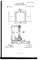
The nature oi'our improvement consistsin the manner of adjusting the swingingof the entire buck part of the camera-box by means 0i' the screw E, which allows and enables the operator to bring the entire back part of the camera-box in any desired position.
The peculiar advantage ot' this improvement will Vbe made plain and fully understood by the following accom panying` drawings In the accompanying drawing, Figure I is the ground plan. Figs. II and V represent the side elevations. Fig. III represents the front ot' the camera-box. Fig. IV represents the plate-holder when the slides are drawn out on both sides.
Similar letters represent similar parts in all the tigures.
A is the bed of the camerabox. B is the bed-plate or the way on which the camera-box is made to move. C is the hinge fastened to the bed-plute, and connecting the same with the entire back part oi' the camera-box. D D represent the views of the entire back part of the camera-box. E E is the screw on the side of the camera for swinging the entire back part of' the camera-box. F is the set-screw on the back part of the camera-box, running in a slot, which, when set, keeps the back part of the camera-box permanently iu a steady position. G, Fig. II, represents the side elevation of the front part of the camerabox, with the shifting front H. H, Fig. III, is the front elevation ofthe camera-box, with the slides H drawn out, as marked by points. I, Fig. IV, is a view of the plate-holder, with the slides I of the plateholder when drawn out on both sides.v K is the plate-holder attached to the camera-box. L is the bcusingscrew. M is the die-frame.
In focusing, the head of the picture will be kept more in the proper position, and the operator will not find any diiiiculty at all in sct ting all the other parts of the picture in the exactly required line.
In order to obtain this el'ect the operator should proceed as follows, viz: Give a single turning to the screw E, and the entire back part ofthe camera-box will be moved forward and backward, and by fastenin g the screw F, Fig. V, the entire back part of the camerabox will be kept'permanently in a steady, unchangeable position.
In the opera-tion of taking the picture, the sliding front part of the camera-box H, Fig.
V, should he drawn out on one side, and the slide I, Fig. 1V, of the stationary plate-holder should also be drawn out on the same side; then, in. closing, the plate-holder should be moved to the other side, and accordingly the slide I oi' the plate-holder should be drawn out for taking the other impression. a
What we claim as our invention, and desire to secure by Letters Patent, is
The adjusting-screw E on the entire back part ot' the camera-box D, working by nut or nuts, in combination with the bed-plate B, for adjusting the camera-box D, in the manner as described.
JOHN STOCK. JACOB STOCK. Witnesses:
AUG. G. ScEELLEn., JULIUs L. Kersen.
Publications (1)
| Publication Number | Publication Date |
|---|---|
| US166315A true US166315A (en) | 1875-08-03 |
Family
ID=2235724
Family Applications (1)
| Application Number | Title | Priority Date | Filing Date |
|---|---|---|---|
| US166315D Expired - Lifetime US166315A (en) | Improvement in photographic cameras |
Country Status (1)
| Country | Link |
|---|---|
| US (1) | US166315A (en) |
-
0
- US US166315D patent/US166315A/en not_active Expired - Lifetime
Similar Documents
| Publication | Publication Date | Title |
|---|---|---|
| US166315A (en) | Improvement in photographic cameras | |
| US140747A (en) | Improvement in joiners clamps | |
| US369997A (en) | Alfred w | |
| US321139A (en) | Monken | |
| US260605A (en) | Photographic camera | |
| US751116A (en) | Ferdinand stark | |
| US363961A (en) | Vignetter | |
| US406934A (en) | Orlo lenard hunger | |
| US49315A (en) | Improvement in photographic cameras | |
| US357752A (en) | irving adams | |
| US258350A (en) | Ebastus b | |
| US745272A (en) | Photographic shutter. | |
| US470783A (en) | dobbs | |
| US201709A (en) | Improvement in flooring-clamps | |
| US632472A (en) | Kinetoscopic apparatus. | |
| US71911A (en) | Multiplying-eeflectoes poe peotogeaphic gameeas | |
| US28739A (en) | cokbett | |
| US704378A (en) | Photographic-camera attachment. | |
| US484179A (en) | Finder attachment for cameras | |
| US220846A (en) | Improvement in adjustable harness-pads | |
| US255567A (en) | Camera box | |
| US329599A (en) | Peters | |
| US1312674A (en) | Camera attachment | |
| US738073A (en) | Camera. | |
| US493365A (en) | Ground-glass adjuster for cameras |