US1663157A - Air-venting valve - Google Patents
Air-venting valve Download PDFInfo
- Publication number
- US1663157A US1663157A US42973A US4297325A US1663157A US 1663157 A US1663157 A US 1663157A US 42973 A US42973 A US 42973A US 4297325 A US4297325 A US 4297325A US 1663157 A US1663157 A US 1663157A
- Authority
- US
- United States
- Prior art keywords
- air
- valve
- rod
- release
- piston
- Prior art date
- Legal status (The legal status is an assumption and is not a legal conclusion. Google has not performed a legal analysis and makes no representation as to the accuracy of the status listed.)
- Expired - Lifetime
Links
Images
Classifications
-
- B—PERFORMING OPERATIONS; TRANSPORTING
- B60—VEHICLES IN GENERAL
- B60T—VEHICLE BRAKE CONTROL SYSTEMS OR PARTS THEREOF; BRAKE CONTROL SYSTEMS OR PARTS THEREOF, IN GENERAL; ARRANGEMENT OF BRAKING ELEMENTS ON VEHICLES IN GENERAL; PORTABLE DEVICES FOR PREVENTING UNWANTED MOVEMENT OF VEHICLES; VEHICLE MODIFICATIONS TO FACILITATE COOLING OF BRAKES
- B60T15/00—Construction arrangement, or operation of valves incorporated in power brake systems and not covered by groups B60T11/00 or B60T13/00
- B60T15/02—Application and release valves
- B60T15/36—Other control devices or valves characterised by definite functions
- B60T15/54—Other control devices or valves characterised by definite functions for controlling exhaust from triple valve or from brake cylinder
Definitions
- This invention relates to an improved air release for auxiliary reservoirs, particularly adapted for the auxiliary reservoirs of the air brakes now used on railroad cars. Obvi- 6 ously, however, this invention may be used on other auxiliary reservoirs of suitable type without departing in any manner from the spirit of this invention.
- auxiliary reservoirs of suitable type without departing in any manner from the spirit of this invention.
- One of the principal objects of this invention is to provide mechanical means for holding the air release in exhaust position, thereby saving the time of the train crew, and materially expediting the work of train switching.
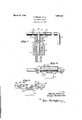
- Fig. 1 illustrates an elevation showing one modification of this invention in assemble form, with the valve in section showing the construction of an ordinary release valve in combination with a lever and cam actuating mechanism of the revolving type.
- Fig. 2 represents a top view of the airvalve showing a modified form of the air releasing mechanism as disclosed in Fig. 1.
- Fig. 3 illustrates a top view of the air valve disclosing in combination therewith a modified form of lever and cam air release mechanism, of the pulling type.
- Numeral 1 designates the housing of the ordinary air auxiliary reservoi for brakes, commonly used, for instance, on railroad cars, while numeral 2 represents the valve piston, and 3 the seat, held in tension by spring 9, the valve being shown in Fig. 1 in closed relation as at 4.
- V the valve piston
- a lever arm 8 In order to release the air by depressing the piston, a lever arm 8 is provided having circular grooves 7 at predetermined inter vals, adapted to lock in sliding relation with rods 5 connected to suitable projecting portions of housing 1.
- a groove 6 is located in the rod and is adapted to receive the release piston whenever the valve is closed, as clearly shown in the drawings. The groove 6 is cut in the rod 8 to give the eilect of a cam motion whenever the rod is turned,
- FIG. 2 A modified form of this invention is shown in Fig. 2, in which numeral 11 designates a support for the rod 13, and 14 the stop lugs for .guiding the revolving motion of the rod, which tends to depress the piston 2 as it slides out of the groove 12, thereby releasing the air through the valve 1.
- FIG. 3 Another modification of this invention is disclosed in Fig. 3 in which the rod 15 is adapted to slide in slots 17 guided by pins 18, thereby causing the piston head 2 to slide out the groove in the rod, and depress the valve seat 8, causing a release of air
- Numerals 16 represents attaching points for the sliding rod 15.
- This invention is inexpensive to make, and simple of operation, as applied to the air release for the auxiliary reservoir of air brakes now used on railroad cars it is highly efficient.
- the present practice when cutting a car loose from an engine, is to pull a lever and hold it until the air is released.
- This invention makes it possible to release the air valve by a simple turn or pull of a rod, at the same time setting the device at the release position, thereby enabling one operator to walk down a string of cars and bleed them in the same time that one could be bled in the old Way. Obviously, valuable time of the whole train crew would be saved.
- An air brake auxiliary reservoir casing having a guide bore at one end thereof, a piston valve reciprocable in said casing to control the release of air therefrom and having a guide stem longer than and slidable in said bore, a spring in said casing to maintain the piston valvenormally closed with the stem thereof normally projecting endwise from said bore, and a rod rotatably mounted on said casing and having a cam part in slidable engagement with the projecting end of said stem and operable by the rotation of said rod to control the opening and closing of said valve.
Landscapes
- Engineering & Computer Science (AREA)
- Transportation (AREA)
- Mechanical Engineering (AREA)
- Valves And Accessory Devices For Braking Systems (AREA)
Description
March 20, 1928. 1,663,157
H. BROWN ET AL AIR VENTING VALVE Filed July 11. 1925 a v I v i 16 Haiold fimwm? ozmmo Patented Mar. 20, 1928.
one
HAROLD BROWN,
1,663,157 FFICE.
OF KANSAS CITY, AND GEORGE RUDOLPH URL, TONGONOXIE,
A CORPORATION OF KANSAS.
AIR-VENTING VALVE.
Application filed July 11, 1925.
This invention relates to an improved air release for auxiliary reservoirs, particularly adapted for the auxiliary reservoirs of the air brakes now used on railroad cars. Obvi- 6 ously, however, this invention may be used on other auxiliary reservoirs of suitable type without departing in any manner from the spirit of this invention. At the present time, in the case of bleeding air brake auxiliary l reservoirs, it is common practice to bleed the reservoir or car before cutting loose from the engine in switching, for instance. To accomplish this, a member of the train crew pulls a lever and holds it for a minute and a half or more for each car switched. One of the principal objects of this invention is to provide mechanical means for holding the air release in exhaust position, thereby saving the time of the train crew, and materially expediting the work of train switching.
In the drawings,
Fig. 1 illustrates an elevation showing one modification of this invention in assemble form, with the valve in section showing the construction of an ordinary release valve in combination with a lever and cam actuating mechanism of the revolving type.
Fig. 2 represents a top view of the airvalve showing a modified form of the air releasing mechanism as disclosed in Fig. 1.
Fig. 3 illustrates a top view of the air valve disclosing in combination therewith a modified form of lever and cam air release mechanism, of the pulling type.
Similar numerals in the 'difierent views represent the same element. v
Numeral 1 designates the housing of the ordinary air auxiliary reservoi for brakes, commonly used, for instance, on railroad cars, while numeral 2 represents the valve piston, and 3 the seat, held in tension by spring 9, the valve being shown in Fig. 1 in closed relation as at 4. V
In order to release the air by depressing the piston, a lever arm 8 is provided having circular grooves 7 at predetermined inter vals, adapted to lock in sliding relation with rods 5 connected to suitable projecting portions of housing 1. A groove 6 is located in the rod and is adapted to receive the release piston whenever the valve is closed, as clearly shown in the drawings. The groove 6 is cut in the rod 8 to give the eilect of a cam motion whenever the rod is turned,
thereby depressing the piston and releasing Serial No. 42,973.
the air on revolving the rod 8. Obviously, the air piston 2 will remain as long as esired in released position, or set without further attention of the operator, until it is desired to close the valve. I
A modified form of this invention is shown in Fig. 2, in which numeral 11 designates a support for the rod 13, and 14 the stop lugs for .guiding the revolving motion of the rod, which tends to depress the piston 2 as it slides out of the groove 12, thereby releasing the air through the valve 1.
Another modification of this invention is disclosed in Fig. 3 in which the rod 15 is adapted to slide in slots 17 guided by pins 18, thereby causing the piston head 2 to slide out the groove in the rod, and depress the valve seat 8, causing a release of air Numerals 16 represents attaching points for the sliding rod 15.
This invention is inexpensive to make, and simple of operation, as applied to the air release for the auxiliary reservoir of air brakes now used on railroad cars it is highly efficient. The present practice, when cutting a car loose from an engine, is to pull a lever and hold it until the air is released. This invention makes it possible to release the air valve by a simple turn or pull of a rod, at the same time setting the device at the release position, thereby enabling one operator to walk down a string of cars and bleed them in the same time that one could be bled in the old Way. Obviously, valuable time of the whole train crew would be saved.
- What we claim is An air brake auxiliary reservoir casing having a guide bore at one end thereof, a piston valve reciprocable in said casing to control the release of air therefrom and having a guide stem longer than and slidable in said bore, a spring in said casing to maintain the piston valvenormally closed with the stem thereof normally projecting endwise from said bore, and a rod rotatably mounted on said casing and having a cam part in slidable engagement with the projecting end of said stem and operable by the rotation of said rod to control the opening and closing of said valve.
In testimony whereof we affix our signatures.
HAROLD BROWN. enonen RUDOLPH UHL.
Priority Applications (1)
| Application Number | Priority Date | Filing Date | Title |
|---|---|---|---|
| US42973A US1663157A (en) | 1925-07-11 | 1925-07-11 | Air-venting valve |
Applications Claiming Priority (1)
| Application Number | Priority Date | Filing Date | Title |
|---|---|---|---|
| US42973A US1663157A (en) | 1925-07-11 | 1925-07-11 | Air-venting valve |
Publications (1)
| Publication Number | Publication Date |
|---|---|
| US1663157A true US1663157A (en) | 1928-03-20 |
Family
ID=21924759
Family Applications (1)
| Application Number | Title | Priority Date | Filing Date |
|---|---|---|---|
| US42973A Expired - Lifetime US1663157A (en) | 1925-07-11 | 1925-07-11 | Air-venting valve |
Country Status (1)
| Country | Link |
|---|---|
| US (1) | US1663157A (en) |
-
1925
- 1925-07-11 US US42973A patent/US1663157A/en not_active Expired - Lifetime
Similar Documents
| Publication | Publication Date | Title |
|---|---|---|
| US1663157A (en) | Air-venting valve | |
| US1548725A (en) | Control mechanism for motor vehicles | |
| GB267889A (en) | Improvements in braking arrangements for vehicles having explosion motors | |
| US1918025A (en) | Brake valve | |
| US1494734A (en) | Air brake | |
| US1619821A (en) | Bleeder attachment for air brakes | |
| US1554013A (en) | Locking means for release valves | |
| US1549772A (en) | Automotive brake equipment | |
| US1689077A (en) | Brake-valve-bleeding device | |
| US1857266A (en) | Valve actuator | |
| US1729397A (en) | Device for stopping railroad trains independently of the driver | |
| US2268953A (en) | Locomotive brake control attachment | |
| US2268516A (en) | Automobile brake | |
| US1553600A (en) | Safety automotive brake | |
| US1773166A (en) | Air brake for automotive vehicles | |
| US1841513A (en) | Automatic slack adjuster | |
| US1700053A (en) | Bell-ringer valve | |
| US2363727A (en) | Throttle control | |
| US2645763A (en) | Railway warning light control system | |
| US2065212A (en) | Brake apparatus for cars | |
| US1887231A (en) | Control mechanism for motor cars | |
| US1840733A (en) | Automatic air release | |
| US1980334A (en) | Door and brake valve device | |
| US1167910A (en) | Automatic train-stopping device. | |
| US1315165A (en) | Holding means eor drain-valves of air-brake systems |