US1663154A - Pulley - Google Patents
Pulley Download PDFInfo
- Publication number
- US1663154A US1663154A US754779A US75477924A US1663154A US 1663154 A US1663154 A US 1663154A US 754779 A US754779 A US 754779A US 75477924 A US75477924 A US 75477924A US 1663154 A US1663154 A US 1663154A
- Authority
- US
- United States
- Prior art keywords
- pulley
- rope
- fingers
- members
- engaging
- Prior art date
- Legal status (The legal status is an assumption and is not a legal conclusion. Google has not performed a legal analysis and makes no representation as to the accuracy of the status listed.)
- Expired - Lifetime
Links
- 239000000314 lubricant Substances 0.000 description 2
- 239000007787 solid Substances 0.000 description 2
- 229910000831 Steel Inorganic materials 0.000 description 1
- 230000032683 aging Effects 0.000 description 1
- 230000005540 biological transmission Effects 0.000 description 1
- 230000001419 dependent effect Effects 0.000 description 1
- 238000006073 displacement reaction Methods 0.000 description 1
- 230000000694 effects Effects 0.000 description 1
- 239000011435 rock Substances 0.000 description 1
- 239000010959 steel Substances 0.000 description 1
- 239000002699 waste material Substances 0.000 description 1
Images
Classifications
-
- F—MECHANICAL ENGINEERING; LIGHTING; HEATING; WEAPONS; BLASTING
- F16—ENGINEERING ELEMENTS AND UNITS; GENERAL MEASURES FOR PRODUCING AND MAINTAINING EFFECTIVE FUNCTIONING OF MACHINES OR INSTALLATIONS; THERMAL INSULATION IN GENERAL
- F16H—GEARING
- F16H55/00—Elements with teeth or friction surfaces for conveying motion; Worms, pulleys or sheaves for gearing mechanisms
- F16H55/32—Friction members
- F16H55/36—Pulleys
- F16H55/50—Features essential to rope pulleys
Definitions
- PATEN 'orFicE PATEN 'orFicE.
- My invention relates to pulleys for the transmission of power, my object being to provide a pulley especially suited for use with rope form belting which by automat c action will assure the requisite friction grip
- rope I mean any belt that is round in cross section whether cordage or made of steel wire and do not limit myself to any particular size of rope nor to any particular number of lines of rope drive as the principle of my invention may be embodied in pulleys for single, double or any number of lines.
- I contemplate embodying my invention inpulleys that are a unit from shaft to circumference or rim and also where the rim and central portion are separate units so that the rim is emountable.
- My invention consists in whatever is described by or is included within the terms or scope of the appended claims.
- a pulley embodying my invention has a rope receiving circumferential groove so that there are what in effect are two opposing annular flanges or 1aws between which the rope lies, and briefly described my invention is embodied in a pulley in which one of the rope engaging 1aws is a solid or continuous flange while the other jaw consists of a circumferential-series of side by side segmentshaving a pivotal connection with the stationary flange so that the segments may rock or swing towards and from the continuous flange to suit the thickness of the rope between the two flanges, and a stand or support is provided with arms or members between which the pulley flanges members yieldably engages the outer side of the segments and by spring action presses said segments against the rope lying between them and the solid or continuous flange of the pulley.
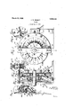
- Fig. 1 is a side
- Fig. 2 is a vertical section on line 52- 2.
- FIG. 5 is an end view of a-two-line pulley.
- the pulley comprises two disk-form members, one designated, 10, whose per1ph eral portion or circumference forms the continuous rope engaging flange or jaw, 11, which on its rope engaging side tapers on a curve outwardly. from the rope engaging rim, 12, which may be any diameter say te'n inches, for.
- the segments designated, 14: are pivoted to lugs, 10*, on the member, 10, and the segments 14 are pivoted to lugs 13" on the member, 13, which lugs 13 extend in spaces between the pairs 0 lugs 10
- Each segment has a reduced portion or' tongue, 15, which extends between the pair of lugs towhich the segment is piv- .from the continuous rope engaging flange, 11,- but that tendency is opposed by the stronger spring pressure which-is brought to vbear upon the outer sides of the segments by the stand hereintofore mentioned between opposing portions of which the pulley revolves as hereinafter more fullyset'forth'.
- the two pulley members firmly secured together by a number of bolts, 17 which extend through them from side to side-parallel with the hole for the shaft, 19, which extends through them.
- a chamber or space is provided between the members, 10, and 18, concentric with the shaft,
- the ends of the plate, 26, are bevelled to allow the easy passage of the. rollers, as shown at 260, Fig. '2.
- av coil spring 29,.upon each of the :bolts,xwhioh at one .end bears against'the side of the IHOV- able plate, 26, .and at the other end bears against ar-shoulder or projection on the bolt so -as to movethe.
- thecoil spring 29,.is placed around a s1eeve,.30, fitted .overthe bolt and confinedzthereon bya nut, 31,;and' having a lip-or flange, 32, against which thespring bears: .
- the ends of the movablev plate segdiametrically has a central hole throughwhich the shaft, 19, passes and midwaybetween-suchf extremities said segment, 26,- has an anti-friction roller, 34, which engages a-notch, '35, in the-standard, while allowing free movement of the ment, 26,..are connected .by a
- an oil cup, 36 maybe provided which-is supported on the segment, 26, and having an. outlet pipe or tube, 37, with .a .wick inposition-to deliver oil to such rollers, 27,.as they; pass the .wick inthe revolution of the pulley the oil thus delivered being led to the roller pivots.
- a grooved pulley for cooperation-with a rope passing partially over the circumference of the pulley, said pulley ghaving laterally movable rope-engaging fingers with surfaces that engage only the rope side,
- a grooved-pulley havingv an annular flange that forms onewallaof the groove and a rope engaging rim at the bottom of the groove and having the opposite .wallflof the groove formed .of in a circular series circumferentially of the pulley certainof-said fingers being pivoted to said rim and an opposing member to which other of said fingers are pivoted;
- a groovedpulley having laterallymovable rope engaging fingers, the opposing wall of the groove being stationary. as to lateral movement, and astand having members upon oppositesides. of the pulleyv one of said members fingers and yieldingly pressing against. said ngers.
- A. grooved by side shaft-engaging members one of which has a rope engaging rima-nd a flange extending outwardly from such rim, two sets of circumferentially extending series of rope engaging fingers extending; radially beyond said rim and opposite said flange, one. of said sets being pivoted to each of said members, and means acting automatically to press said fingers towards .saidwfiange.
- a grooved pulley comprising twoside by side shaft which has a rope: engaging rim and a flange from such rim, two sets of circumferentiallyextending series of rope engaging fingers extending radially beyond said rim and opposite. saidwflange one of said sets being pivoted to one of saidmembers and the other set being pivoted to the other of. said menton the outer side of said fingershaving a surface in contact therewith, spring means pivoted fingers extending normally, engaging said pulley comprising .two side a pulley comprising two side engagingmembers, one of. which has a rope engaging rim and a flangeengaging members, one a of acting upon said element to move it towards the fingers, a stationary support for said element, and means to prevent said element rotating while allowing axial movement thereof.
- a grooved pulley having laterally movable rope engaging fingers, the opposing Wall of the groove being stationary as to lateral movement, a stand having members upon opposite sides of the pulley one of said 1 In testimony whereof I hereunto aflix my signature.
Landscapes
- Engineering & Computer Science (AREA)
- General Engineering & Computer Science (AREA)
- Mechanical Engineering (AREA)
- Pulleys (AREA)
- Devices For Conveying Motion By Means Of Endless Flexible Members (AREA)
Description
March 20, 192-8;
J. W. BISSETT v PULLEY v Filed Dec. 9, 1924 'of pulley and rope.
Patented Mar. 20, 1928.
PATEN 'orFicE.
JOHN w. BIssn'r'r, or GARRISON, PENNSYLVANIA.
IULLEY.
Application filed December 9, 1924. Serial No. 754,779.
My invention relates to pulleys for the transmission of power, my object being to provide a pulley especially suited for use with rope form belting which by automat c action will assure the requisite friction grip By rope I mean any belt that is round in cross section whether cordage or made of steel wire and do not limit myself to any particular size of rope nor to any particular number of lines of rope drive as the principle of my invention may be embodied in pulleys for single, double or any number of lines. I contemplate embodying my invention inpulleys that are a unit from shaft to circumference or rim and also where the rim and central portion are separate units so that the rim is emountable. My invention consists in whatever is described by or is included within the terms or scope of the appended claims.
As will be evident a pulley embodying my invention has a rope receiving circumferential groove so that there are what in effect are two opposing annular flanges or 1aws between which the rope lies, and briefly described my invention is embodied in a pulley in which one of the rope engaging 1aws is a solid or continuous flange while the other jaw consists of a circumferential-series of side by side segmentshaving a pivotal connection with the stationary flange so that the segments may rock or swing towards and from the continuous flange to suit the thickness of the rope between the two flanges, and a stand or support is provided with arms or members between which the pulley flanges members yieldably engages the outer side of the segments and by spring action presses said segments against the rope lying between them and the solid or continuous flange of the pulley. Hereinafter is a detailed description of what appears i the drawings as what I now consider satisfactory embodiments of the principle of my invention. In'the accompanying drawings: Fig. 1 is a side View of a drive pulley embodying my invention;
Fig. 2 is a vertical section on line 52- 2.
of Fig. 1'
Figs. 3
tive of portions of the rope engaging members' r Fig. 5 is an end view of a-two-line pulley.
Referring first to what is shown in Figs.
- of ten inches. T0
are situated, one of which 19, by an annular 7 I o n and 4; are detail views in perspec- 1 to 3 the pulley comprises two disk-form members, one designated, 10, whose per1ph eral portion or circumference forms the continuous rope engaging flange or jaw, 11, which on its rope engaging side tapers on a curve outwardly. from the rope engaging rim, 12, which may be any diameter say te'n inches, for. the sake of illustration'and the other member, 13, which has a diameter say both members in-an alternating arrangement are pivoted segments, 1 1, and 14:, which constitute theiother rope engaging, flange of the pulley and whose faces towards the-rope are tapered irr correspondence with the taper of the opposing continuous flange, 11'. The segments designated, 14:, are pivoted to lugs, 10*, on the member, 10, and the segments 14 are pivoted to lugs 13" on the member, 13, which lugs 13 extend in spaces between the pairs 0 lugs 10 Each segment has a reduced portion or' tongue, 15, which extends between the pair of lugs towhich the segment is piv- .from the continuous rope engaging flange, 11,- but that tendency is opposed by the stronger spring pressure which-is brought to vbear upon the outer sides of the segments by the stand hereintofore mentioned between opposing portions of which the pulley revolves as hereinafter more fullyset'forth'.
The two pulley members, firmly secured together by a number of bolts, 17 which extend through them from side to side-parallel with the hole for the shaft, 19, which extends through them. A chamber or space is provided between the members, 10, and 18, concentric with the shaft,
wall, 18, that forms a lubricant reservoir for holding waste and oil in such wall which 'is'provided with radial holes, 20, to allow lubricant to findits way to the pivots of the segments. Oil is supplied such reservoir through a hole,21, leading'into thesame through the member, 18.
'Stationarily supported by lugs, 22, is a IQ, and 13, are
14, under the: pull of suchv standard, .23,'from which a segment shape or semi-circular plate, 2 1, extends alongside 23, and I segment,.26, inan/axial direction prevents several holes in said plate, 24, parallel with the pulley axis are rods orbolts, 25, which are fixed to a substantially similar plate, 26, upon the opposite side of the pulley, and which by spring pressure engages the outer sides of the segments or anti-friction rollers, 27, mounted thereon so that as the segments revolvewith or as a part ofthe pulley they are thereby pressed against the rope belt, 28,lying.in the pulley groove.
The ends of the plate, 26, are bevelled to allow the easy passage of the. rollers, as shown at 260, Fig. '2. upon the plate, 26, which causes the automatic adjustment of thickness of the rope is produced by av coil spring, 29,.upon each of the :bolts,xwhioh at one .end bears against'the side of the IHOV- able plate, 26, .and at the other end bears against ar-shoulder or projection on the bolt so -as to movethe. pressureproducing plate, 26, against thesides of the segments, 14, and, 14 Preferably thecoil spring, 29,.is placed around a s1eeve,.30, fitted .overthe bolt and confinedzthereon bya nut, 31,;and' having a lip-or flange, 32, against which thespring bears: .The ends of the movablev plate segdiametrically has a central hole throughwhich the shaft, 19, passes and midwaybetween-suchf extremities said segment, 26,- has an anti-friction roller, 34, which engages a-notch, '35, in the-standard, while allowing free movement of the ment, 26,..are connected .by a
any displacement thereof in a circular direction. .To lubricate the anti-friction rollers, 27, on-the. segment an oil cup, 36, maybe provided which-is supported on the segment, 26, and having an. outlet pipe or tube, 37, with .a .wick inposition-to deliver oil to such rollers, 27,.as they; pass the .wick inthe revolution of the pulley the oil thus delivered being led to the roller pivots.
I show 'in Fig. .5 a pulley for a two-line drive which as will be evident. involves merely-the duplication of parts shown in Figs. 1 to 3, there being thustwo sets of segments corresponding to the segments, 14, and 14, and theiduplication of..the single tapered flange, 11, and the duplication of the pulley members corresponding with the member,
l3. andalso ofthe adjustable or automatically shiftable se ment en aging plate 26.
'What I claim is: D
1. A grooved pulley for cooperation-with a rope passing partially over the circumference of the pulley, said pulley ghaving laterally movable rope-engaging fingers with surfaces that engage only the rope side,
wherebythe rope is freeto move in a direction radial of the pulley intoand out of contactwith the circumferencefthereo'f,..and fl automatic means to press such fingers yieldable outwardly,
against the rope side The spring pressure the pulley .to the size or I extending outwardly thQdIlOVBlllGIli] of the fingers outward deable rope engaging fingers, and means to press said fingers towards the rope automatically and yieldable automatically out- .Ward, thewfingers being at all times free to move dependent upon the thickness of the ro e.
3 A grooved-pulley havingv an annular flange that forms onewallaof the groove and a rope engaging rim at the bottom of the groove and having the opposite .wallflof the groove formed .of in a circular series circumferentially of the pulley certainof-said fingers being pivoted to said rim and an opposing member to which other of said fingers are pivoted;
4. A groovedpulleyhaving laterallymovable rope engaging fingers, the opposing wall of the groove being stationary. as to lateral movement, and astand having members upon oppositesides. of the pulleyv one of said members fingers and yieldingly pressing against. said ngers.
5. A. grooved by side shaft-engaging members, one of which has a rope engaging rima-nd a flange extending outwardly from such rim, two sets of circumferentially extending series of rope engaging fingers extending; radially beyond said rim and opposite said flange, one. of said sets being pivoted to each of said members, and means acting automatically to press said fingers towards .saidwfiange.
6. Agrooved, byv side shaft 7. A grooved pulley comprising twoside by side shaft which has a rope: engaging rim and a flange from such rim, two sets of circumferentiallyextending series of rope engaging fingers extending radially beyond said rim and opposite. saidwflange one of said sets being pivoted to one of saidmembers and the other set being pivoted to the other of. said menton the outer side of said fingershaving a surface in contact therewith, spring means pivoted fingers extending normally, engaging said pulley comprising .two side a pulley comprising two side engagingmembers, one of. which has a rope engaging rim and a flangeengaging members, one a of acting upon said element to move it towards the fingers, a stationary support for said element, and means to prevent said element rotating while allowing axial movement thereof.
8. A grooved pulley having laterally movable rope engaging fingers, the opposing Wall of the groove being stationary as to lateral movement, a stand having members upon opposite sides of the pulley one of said 1 In testimony whereof I hereunto aflix my signature.
JOHN W. BIQSSETT.
Priority Applications (1)
| Application Number | Priority Date | Filing Date | Title |
|---|---|---|---|
| US754779A US1663154A (en) | 1924-12-09 | 1924-12-09 | Pulley |
Applications Claiming Priority (1)
| Application Number | Priority Date | Filing Date | Title |
|---|---|---|---|
| US754779A US1663154A (en) | 1924-12-09 | 1924-12-09 | Pulley |
Publications (1)
| Publication Number | Publication Date |
|---|---|
| US1663154A true US1663154A (en) | 1928-03-20 |
Family
ID=25036299
Family Applications (1)
| Application Number | Title | Priority Date | Filing Date |
|---|---|---|---|
| US754779A Expired - Lifetime US1663154A (en) | 1924-12-09 | 1924-12-09 | Pulley |
Country Status (1)
| Country | Link |
|---|---|
| US (1) | US1663154A (en) |
Cited By (3)
| Publication number | Priority date | Publication date | Assignee | Title |
|---|---|---|---|---|
| US2447298A (en) * | 1944-09-14 | 1948-08-17 | Raymond C Whitlock | Chain saw |
| DE2739423A1 (en) * | 1977-09-01 | 1979-03-08 | Rotzler Gmbh Co | THROUGH WINCH |
| US5078058A (en) * | 1989-10-10 | 1992-01-07 | Horst Schwede | Tensioning device for a packaging tape |
-
1924
- 1924-12-09 US US754779A patent/US1663154A/en not_active Expired - Lifetime
Cited By (3)
| Publication number | Priority date | Publication date | Assignee | Title |
|---|---|---|---|---|
| US2447298A (en) * | 1944-09-14 | 1948-08-17 | Raymond C Whitlock | Chain saw |
| DE2739423A1 (en) * | 1977-09-01 | 1979-03-08 | Rotzler Gmbh Co | THROUGH WINCH |
| US5078058A (en) * | 1989-10-10 | 1992-01-07 | Horst Schwede | Tensioning device for a packaging tape |
Similar Documents
| Publication | Publication Date | Title |
|---|---|---|
| US2556512A (en) | Variable ratio drive mechanism | |
| US1663154A (en) | Pulley | |
| US2082842A (en) | One-way clutch | |
| US834499A (en) | Clutch device. | |
| US2298535A (en) | Drive mechanism | |
| US1925072A (en) | Internal combustion engine | |
| US1879633A (en) | Hydraulically controlled variable speed pulley | |
| US1829657A (en) | Securing element | |
| US2728240A (en) | Tension or guide pulley apparatus | |
| US1455587A (en) | Clutch | |
| US1256947A (en) | Automatic stress-relieving friction-pulley or power-transmission mechanism. | |
| US2359654A (en) | Lubricating arrangement | |
| US1499583A (en) | Construction of stuffing boxes for revolving shafts of all kinds and especially of turbine shafts and the like | |
| US1583530A (en) | Clutch mechanism | |
| US1824431A (en) | Clutch | |
| US2024677A (en) | Automatic friction clutch | |
| US1659286A (en) | Centrifugal friction clutch | |
| US20150226291A1 (en) | Dry variable speed drive mechanism | |
| US2312889A (en) | Centrifugally operated clutch | |
| US1507543A (en) | Flexible clutch | |
| US1927501A (en) | Machine for rolling sheet metal shapes | |
| US2036445A (en) | Adjustable v-type pulley | |
| US1381745A (en) | Power-transmitting mechanism | |
| US1974108A (en) | Variable speed transmission | |
| US2010793A (en) | Driving mechanism |