US1663145A - Manifold-web-printing machine - Google Patents
Manifold-web-printing machine Download PDFInfo
- Publication number
- US1663145A US1663145A US119279A US11927926A US1663145A US 1663145 A US1663145 A US 1663145A US 119279 A US119279 A US 119279A US 11927926 A US11927926 A US 11927926A US 1663145 A US1663145 A US 1663145A
- Authority
- US
- United States
- Prior art keywords
- web
- work
- roll
- feed
- carbons
- Prior art date
- Legal status (The legal status is an assumption and is not a legal conclusion. Google has not performed a legal analysis and makes no representation as to the accuracy of the status listed.)
- Expired - Lifetime
Links
- OKTJSMMVPCPJKN-UHFFFAOYSA-N Carbon Chemical compound [C] OKTJSMMVPCPJKN-UHFFFAOYSA-N 0.000 description 24
- 229910052799 carbon Inorganic materials 0.000 description 22
- 238000004804 winding Methods 0.000 description 5
- 241000282472 Canis lupus familiaris Species 0.000 description 4
- 238000010276 construction Methods 0.000 description 4
- 238000009499 grossing Methods 0.000 description 1
- 230000007775 late Effects 0.000 description 1
Images
Classifications
-
- B—PERFORMING OPERATIONS; TRANSPORTING
- B41—PRINTING; LINING MACHINES; TYPEWRITERS; STAMPS
- B41K—STAMPS; STAMPING OR NUMBERING APPARATUS OR DEVICES
- B41K3/00—Apparatus for stamping articles having integral means for supporting the articles to be stamped
- B41K3/54—Inking devices
- B41K3/58—Inking devices using ink ribbons, ink sheets, or carbon tape or paper
Definitions
- This invention relates to the construction of manifold-web-printing machines both inconnection with a typewriting machine and independently thereof.
- long rolls of carbon are employed instead of relatively short sheets, and means are provided for feedin carbons from rolls at either side of the we and for conducting the carbons between the superposed plies over the stamping or printing bed, and then winding them upon a take-up roll.
- a feature of the invention resides in the provision of pairs of diagonal guides, which are arranged for conducting a carbon in between superposed plies of a longitudinally fan-folded work-web from a feed roll lo cated at one side of the web, thence along the work-Web over the printing bed, and out again to be wound up on a take-up roll.
- the guides are positioned on both sides'of the web whenever the latter includes more than two plies.
- Another feature resides in positioning a pair of such diagonal guldes with the feed-roll aide in front of the guide oposite the ta e-up roll, and arranging the atter with means to prevent it from unwinding.
- the drag of the interleaved work-plies as they are moved forward according to this arran ement tends to keep the carbon smooth an taut without danger of unwinding it from the feed-roll or takeup roll.
- Figure 1 is a partial longitudinal seccarbon-take-up roll which may be employed in the present invention.
- Figure 4 is a diagrammatic view illustrating how a plurality of carbons maybe interleaved between the work-plies of a lon itudinally-fan-folded work-web from t e sides of the latter.
- Figure 5 is a fragmentary plan view of the printing machine shown in Figure 1.
- Figure 6 is a fragmentary plan view of the printing machine of the invention arranged with feed-rolls, take-up rolls, and diagonal guides for interleaving carbons between the superposed plies of a longitudinally-fan-folded work-web.
- the web-printing machine includes a main frame 10, a printing bed 11, and a platen 12 fastened to an arm 13 which is pivoted about a shaft 14 and which has a lower forwardly-extending lug 15 connected to a plate-feeding mechanism generally designated as 16, which mechanism is arranged to move plates 17 from a magazine 18 over the main frame 10 to the printing bed 11.
- a work-web W may be guided from the rear of the machine over the magazine 18 and along the top of the main frame 10 by rollers 19, 20 and 21.
- the work-Web W may be advanced forwardly over the printing bed by means of rolls 22 and 23, mounted at the front of the frame 10 and arranged to be rotated upon upward movement of the platen 12 by engagement with a gear-segment 24, which may be operatively connected to the arm 13 by a bar 25.
- the construction and operation of the abovementioned parts of the machine may be substantially the same as for like parts described in my above-mentioned application.
- carbon-feed rolls 30 and a take-up roll 31 may be mounted on opposite sides .of the work-web, as shown in Figures 2 and-5,.
- an inked ribbon 32 may be passed across the printing bed under the lowest ply of the superposed work-plies.
- Carbon from the lowermost feed-roll 30 may be passed between the lowest and second lowest workplies, and across the frame to be fastened in any suitable way to the take-up roll 31.
- Carbon from the second lowest feed-roll may be passed between the second and third lowest work-plies, and operatively fastened to the take-up roll 31,
- the carbon from the remaining feed-rolls may be passed between the proper web-plies and fastened to the take-up roll 31, which may have a handle 33 for winding the carbon across the printing bed 11 to bring fresh sections of carbon to position for manifolding the superposed forms.
- the take-up roll may have atoothed wheel 34, and a springpressed dog 35 engaging the toothed wheel to prevent backward rotation of the take-up roll.
- Each carbon after passing from its feed-roll 30 may be led over a roll 36 adjacent the top feed-roll.
- a second roll 37 Cmounted in the end of a spring-pressed bracket 38 may be arranged to press the carbons down against the roll 36' which will tend to cause the carbons to be'unrolled evenly under a suitable tension.
- spring-actuated friction brakes 39 may be arranged in a well-known way around stubshafts 393 so as to engage the feed-rolls 30 and retard the rotation of the latter.
- the carbon of'the feed-rolls may be wound on hollow spindles 30, intocwhich the stubshafts 39 may be fitted. The stub-shafts may be retracted and the feed-rolls easily removed when desired.
- Carbon from the feed-rolls 40 may pass preferably at right angles to the work-web and between two desired workplies, and be turned around a diagonal guide 41 of a guide-plate 42 in the opposite directionto the forward movement of the workweb.
- a carbon may be turned around a second diagonal guide 43 of the plate 42 and be conducted to a take-up roll 45, mounted on the same side of the work-web W as the feed-roll 40 from which the carbon started, and int-he rear of the feed-roll.
- the feedrolls 40 may be arranged with friction brakes 46, likethose employed on feed-rolls 30.
- the take-up rolls 45 may have handles 47, toothed wheels 48 and dogs 49 arranged to function like the similar parts of the takeup roll 31.
- FIG 3 is illustrated an advantageous form of a carbon-take-up roll for use with longitudinally-fan-folded work-webs.
- the spool 45 on which the carbon may be wound, is positioned above a guide-roll 51 whose lower edge is approximately level with the top of the printing bed 11.
- the carbons may be directed along a substantially level plane to the proper guide-plate 42, by which to rotate the spool and a handle 47 may be positioned high enough so as to be clear of the main frame 10 or adjacent feed-rolls 40.
- the friction of the forwardly-moving workplies on the carbons may be utilized to keep the interleaved carbons smooth and taut without danger of unrollin them from the feed-rolls or the take np roils.
- a device for guiding a carbon" from a .source at one side "of a multiplep 5. web into and out of parallel inter eaved re- 7 I lation; with two adjoining plies of said work- .web, -;said.
- a printing bed over. which may 7 be passed a longitudinally-fan-folded work web, and means for guiding carbons from a source at the side of 'said web; into interleaved relation with the plies of said workweb at one side of said printing bed, thence over said printing bed and thence out of.
- a printin bed over whch ma be passed a multiple-p y work-web, a plura s ity of carbons being disposed in interleaved relation with the plies of said work-web, a take-up roll mounted at one side of said .web and arranged for winding thereon all of said carbons, a toothed .wheel fastened at an end of said take-up roll for rotation therewith, a dog arranged for engaging said toothed wheel to revent backward rotation thereof, a plurality of feed-rolls for said I carbons'mounted on the opposite side of said 7' work-web in a vertical row, and a tensioning device forholdin .all of said carbons taut as they are reele 01f their respective feedrolls, said device including a roll for said carbons to pass over, positioned between .'-the uppermost one of said feed-rolls and work-web, and a spring-held] roller arran' edffor pressing said carbons a ains
- a printing bed over which may be passed a longitudinally-fan-folded workweb previously printed with successive forms, a pair of rollers in front of said printing bed arranged for advancing said- Work-web form by form, a vertical row of. carbon-feed rolls disposed on each side of said work-web in front of said printing bed,
- a carbon-take-up roll arranged for rotation only in a forward direction, disposed on each side of said work-web in the rear of saidprinting bed, and means for guiding carbons from said feed-rolls into interleaved relation with the plies of said work-web oversaid printing bed-and out of interleaved relation with said pliesto be wound up on said carbon-'take-up rolls, said guiding means including a stack of plates disposed in the rear of said pair of rollers on each, side of said work-web and projecting into the plies thereof, each of said lates havin a diagonal edge opposite the a j acent row 0 feed-rolls, the second diagonal edge bein disposed opposite the adjacenttake-up rolfi and each of said plates further having a portionover said printing bed cut away, the dimensions of said cut-awa portions measured along said work-we being greater than the similar demensions of said forms.
- a printing bed over folded work-web may. be fed, means for feedin said web from 'r'ear to front, means forta g carbons from. feed-rolls at the sides of said work web in front of said printing bed and interleaving the carbons etween'the plies ofsaid work-web, whereby the drag of'said plies will keep said carbons smooth and taut without danger of unwinding fthem fromf said feed-rolls, said means including a take-up roll on each side 'of said work-web, a stack of plates mounted on each side of said work-web, each 7 plate extendin in between two adjoining plies of said wor -web and having two integral diagonal guide-members arran ed to turn the carbons leading from the ad acent feed-roll to a course parallel with said work-web thence alon with said work-web over sai printing be andthence out to said take-up rolls, and
- a printing bed over which %ay be passed a longitudinally-fan-folded workweb, and means for 'ding carbons from a source at a side of said web into interleaved relation with'the plies of said work-web at no one end, of said printing bed, thence over said printing bed, and thence out of interleaved relation with said plies, said.
- each pair of said guides being disposed to extend inwardly between two adjoining superposed plies of said work-web for turning one of said carbons entering between said work-plies at an angle thereto into longitudinal alignment therewith, and thence away from said workweb at an angle thereto upon the same side from which the carbon entered said workphes.
- a printingbed over which may P be passed a multiple-ply work-web a plurality of carbon-feed-rolls mounted adja cent said printing bed, a carbon-take-up rollmounted in another position adjacent said printing bed, a carbon-'guide-roller between I said feed-rolls and said bed, and a second carbon-guide-roller between said take-up roll and said bed to bring the carbons from said feed-rolls into substantially parallelism with said printing bed in condition to be intcrleaved between portions of said work-web and finally wound on said take-up roll.
- a printing bed over which may be passed a multiple-ply work-web in combination, a printing bed over which may be passed a multiple-ply work-web, a
- a take-up roll mounted at one side of said web and arranged for winding thereon all of said carbons, means to prevent reverse rotation of said take-up roll, a plurality of carbon-feed-rolls for said carbons mounted on the opposite side of said work-web as a group, and a tensioning device for holdingall of said carbons taut as they are reeled off their respective feed-rolls, said device including a roll beneath said carbons disposed between the uppermost one of said feed-rolls and said work-web, and a spring-held roller arranged for pressing said carbons upon said roll positioned between said web and said feed-roll.
- a printing bed o'ver'which may be passed-a longitudinally-fan-folded workweb, and means for guiding carbons from a source at the side of said web into interleaved relation with the plies of said workweb at one side of said printing bed, thence over said printing bed in longitudinal alignment with said work-web, and thence out upon the same side again from interleaved relation with said plies.
- a printing bed over which may be passed a multiple-ply-work-web
- a carbon-feed-roll mounted at one side of said web adjacent said printing bed
- a carbontake-up roll also mounted adjacent said printing bed and adjacent said feed-roll
- guide-means located adjacent said printing bed for turning a carbon-sheet fed from 7 said feed-roll towards said take-up roll
- a printing bedover which may be passed a multiple-ply work-web, a carbonbeing interleaved therewith, a carbon-feed-roll for the carbon mounted at one side of said work-web, a smoothing roller in means to prevent reverse rotation of said take-up roll.
Landscapes
- Folding Of Thin Sheet-Like Materials, Special Discharging Devices, And Others (AREA)
- Inking, Control Or Cleaning Of Printing Machines (AREA)
Description
March 20, 1928. v J. A. B. SMITH MANIFOLD WEB PRINTING MACHINE Filed June 29. 1926 2 Sheets-Sheet].
[/7 1/? far Zv $5 I. a w 4 \x. 2 w 4 o O v A 0 j ,v {v 3 a T wz Cu V O March 20, 1928.
J. A. B. SMITH MANIFOLD WEB PRINTING MACHINE Filed June 29, 1926 2 Sheets-Sheet 2 MIA la L W 22 K27 Z} A War/14y Patented Mar. 20, 19 28.
UNITED STATES 1,663,145, PATENT OFFICE.
JESSE A. B. SMITH, OF STAMFORD, CONNECTICUT, ASSIGNOR TO UNDERWOOD ELLIOTT FISHER COMPANY, OF NEW YORK, N. Y., A CORPORATION OF DELAWARE.
MANIFOLD-WEB-I'RINTING MACHINE.
Application filed Julie 29, 1926. Serial No. 119,279.
This invention relates to the construction of manifold-web-printing machines both inconnection with a typewriting machine and independently thereof.
In my co-pending application, Serial No. 631,956, filed April 14, -1923', (now Patent No. 1,592,470, dated July 13, 1926), there is disclosed a manifold-web-stamping machine in which carbon-sheets are held interleaved between superposed plies of a longitudinallyfan-folded work-web, by means of blades which project transversely to the web between the plies thereof alternately from opposite sides, the blades being positioned to the rear of the stamping bed.
In the present invention, long rolls of carbon are employed instead of relatively short sheets, and means are provided for feedin carbons from rolls at either side of the we and for conducting the carbons between the superposed plies over the stamping or printing bed, and then winding them upon a take-up roll. By employlng long rolls of carbons, fresh sections of which can be fed to printing position as the advance sections become worn, it is not necessary to replace the carbon-manifolding elements as often as when relatively short sheets are used.
A feature of the invention resides in the provision of pairs of diagonal guides, which are arranged for conducting a carbon in between superposed plies of a longitudinally fan-folded work-web from a feed roll lo cated at one side of the web, thence along the work-Web over the printing bed, and out again to be wound up on a take-up roll. As the plies are joined along one side, the guides are positioned on both sides'of the web whenever the latter includes more than two plies. Another feature resides in positioning a pair of such diagonal guldes with the feed-roll aide in front of the guide oposite the ta e-up roll, and arranging the atter with means to prevent it from unwinding. The drag of the interleaved work-plies as they are moved forward according to this arran ement tends to keep the carbon smooth an taut without danger of unwinding it from the feed-roll or takeup roll.
Other features and advantages will hereinafter appear.
In the acc mpanyin drawings,
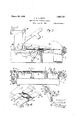
Figure 1 is a partial longitudinal seccarbon-take-up roll which may be employed in the present invention. I
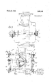
Figure 4 is a diagrammatic view illustrating how a plurality of carbons maybe interleaved between the work-plies of a lon itudinally-fan-folded work-web from t e sides of the latter.
Figure 5 is a fragmentary plan view of the printing machine shown in Figure 1.
Figure 6 is a fragmentary plan view of the printing machine of the invention arranged with feed-rolls, take-up rolls, and diagonal guides for interleaving carbons between the superposed plies of a longitudinally-fan-folded work-web.
The web-printing machine includes a main frame 10, a printing bed 11, and a platen 12 fastened to an arm 13 which is pivoted about a shaft 14 and which has a lower forwardly-extending lug 15 connected to a plate-feeding mechanism generally designated as 16, which mechanism is arranged to move plates 17 from a magazine 18 over the main frame 10 to the printing bed 11.
A work-web W may be guided from the rear of the machine over the magazine 18 and along the top of the main frame 10 by rollers 19, 20 and 21. The work-Web W may be advanced forwardly over the printing bed by means of rolls 22 and 23, mounted at the front of the frame 10 and arranged to be rotated upon upward movement of the platen 12 by engagement with a gear-segment 24, which may be operatively connected to the arm 13 by a bar 25. The construction and operation of the abovementioned parts of the machine may be substantially the same as for like parts described in my above-mentioned application.
For manifolding a work-web whose superposed work-plies are not joined at the'sides, carbon-feed rolls 30 and a take-up roll 31 may be mounted on opposite sides .of the work-web, as shown in Figures 2 and-5,. To print with ink on the original or lowermost member of a set of superposed forms, an inked ribbon 32 may be passed across the printing bed under the lowest ply of the superposed work-plies. Carbon from the lowermost feed-roll 30 may be passed between the lowest and second lowest workplies, and across the frame to be fastened in any suitable way to the take-up roll 31. Carbon from the second lowest feed-roll may be passed between the second and third lowest work-plies, and operatively fastened to the take-up roll 31, In like manner, the carbon from the remaining feed-rolls may be passed between the proper web-plies and fastened to the take-up roll 31, which may have a handle 33 for winding the carbon across the printing bed 11 to bring fresh sections of carbon to position for manifolding the superposed forms. The take-up roll may have atoothed wheel 34, and a springpressed dog 35 engaging the toothed wheel to prevent backward rotation of the take-up roll. Each carbon after passing from its feed-roll 30 may be led over a roll 36 adjacent the top feed-roll. A second roll 37 Cmounted in the end of a spring-pressed bracket 38 may be arranged to press the carbons down against the roll 36' which will tend to cause the carbons to be'unrolled evenly under a suitable tension. To provide additional means for holding the carbons satisfactorily taut between the work-plies, spring-actuated friction brakes 39 may be arranged in a well-known way around stubshafts 393 so as to engage the feed-rolls 30 and retard the rotation of the latter. The carbon of'the feed-rolls may be wound on hollow spindles 30, intocwhich the stubshafts 39 may be fitted. The stub-shafts may be retracted and the feed-rolls easily removed when desired.
To manifold superposed forms of a longitudinally-fan-folded work-web whose plies are connected at the sides, it is impossible to have the carbommanifolding elements pass through the work-web from a feed-roll to a take-up roll in the manner just described above. In order to pass the carbon between superposed work-plies of a longitudinally-fan-folded work-web at the printing bed, and then conduct the carbon to the take-up roll, provision is made in the present invention of feed-rolls 40 mounted on each side of the work-web W in front of the printing bed 11. Carbon from the feed-rolls 40 may pass preferably at right angles to the work-web and between two desired workplies, and be turned around a diagonal guide 41 of a guide-plate 42 in the opposite directionto the forward movement of the workweb. After extending past the printing bed 11, a carbon may be turned around a second diagonal guide 43 of the plate 42 and be conducted to a take-up roll 45, mounted on the same side of the work-web W as the feed-roll 40 from which the carbon started, and int-he rear of the feed-roll. The feedrolls 40 may be arranged with friction brakes 46, likethose employed on feed-rolls 30. The take-up rolls 45 may have handles 47, toothed wheels 48 and dogs 49 arranged to function like the similar parts of the takeup roll 31.
In Figure 3 is illustrated an advantageous form of a carbon-take-up roll for use with longitudinally-fan-folded work-webs. The spool 45, on which the carbon may be wound, is positioned above a guide-roll 51 whose lower edge is approximately level with the top of the printing bed 11. By this construction the carbons may be directed along a substantially level plane to the proper guide-plate 42, by which to rotate the spool and a handle 47 may be positioned high enough so as to be clear of the main frame 10 or adjacent feed-rolls 40.
By making the diagonal carbon-guides 41 and 43 from a single plate 42 and leaving an opening 42 therein over the printing bed 11, an advantageous construction is secured, which gives a very desirable rigidity as Well as economy.
By positioning the feed-roll guide 41 in front of the printing bed 11 and the take-up guide 43 in the rearof the printing bed and arranging to wind new sections of thecarbons into position from frontto rear, that is, in the opposite direction to the movement of the work-web W, and V by arranging the toothed wheels 48 and dogs 49 to prevent the backward rotation of the take-up-rolls 45, the friction of the forwardly-moving workplies on the carbons may be utilized to keep the interleaved carbons smooth and taut without danger of unrollin them from the feed-rolls or the take np roils.
Variations may be resorted to within the scope of the invention, and portions of the improvements may be'uscd without others.
Having thus described my invention, I claim:
1'. In a manifold-web-printing machine, in combination, a printing bed over which may be passed a multiple-ply longitudinally-fan-folded Work-web having a plurality of carbons interleaved therewith, a plate ing one of said carbons which may enter between said workplies at right angles to the same in the opposite direction of the movement of said work-web and thence away from said work-web at right angles and on the same side from which the carbon entered i said work-plies.
2. In a manifold-web-printing machine. in combination, a printing bed over which may be passed a multiple-ply work-web,- a plurality of carbons being interleaved there- 9 7 j l sai 'roll'. positioned between said we i' 6. A device for guiding a carbon" from a .source at one side "of a multiplep 5. web into and out of parallel inter eaved re- 7 I lation; with two adjoining plies of said work- .web, -;said. device "-includm a thin plate [having a dia o'nal j forturning said-car n to lie arallel with the edges of said work-web with, a take-up roll'mounted at one side of said work-web and arranged for winding thereon all of said carbons, means for preventing backward rotation of said take-up 5 roll, and means for holding said carbons taut as they are wound on said take-up roll including 'a spring-operated device.
- 3. In a device of the class described, in
therewith and be wound together on said 0 take-up roll. I v
4. In a device of the class described, in
combination, a printing bed over. which may 7 be passed a longitudinally-fan-folded work web, and means for guiding carbons from a source at the side of 'said web; into interleaved relation with the plies of said workweb at one side of said printing bed, thence over said printing bed and thence out of.
interleaved relation with said plies.
combination, a printin bed over whch ma be passed a multiple-p y work-web, a plura s ity of carbons being disposed in interleaved relation with the plies of said work-web, a take-up roll mounted at one side of said .web and arranged for winding thereon all of said carbons, a toothed .wheel fastened at an end of said take-up roll for rotation therewith, a dog arranged for engaging said toothed wheel to revent backward rotation thereof, a plurality of feed-rolls for said I carbons'mounted on the opposite side of said 7' work-web in a vertical row, and a tensioning device forholdin .all of said carbons taut as they are reele 01f their respective feedrolls, said device including a roll for said carbons to pass over, positioned between .'-the uppermost one of said feed-rolls and work-web, and a spring-held] roller arran' edffor pressing said carbons a ainsg said feed-roll.
1y work- ,mounted'at oneside ofsai work web and ide-member disposed etween. said p11es, and a second guide-member at a dis- I I tunes from said first-named guide-member i and disposed to turn said'carbon transverse- 1y {of said work-web-to the same side as i Y 1 v5. In a manifold-web-printing machine, in
in combination, I which 'a multiple-ply longitudinally-fanthe source ofsaid carbon, said plate having a portion between said guide-members cut away. f
7. In a device of the, class described, in
combination, a printing bed over which may be passed a longitudinally-fan-folded workweb previously printed with successive forms, a pair of rollers in front of said printing bed arranged for advancing said- Work-web form by form, a vertical row of. carbon-feed rolls disposed on each side of said work-web in front of said printing bed,
a carbon-take-up roll arranged for rotation only in a forward direction, disposed on each side of said work-web in the rear of saidprinting bed, and means for guiding carbons from said feed-rolls into interleaved relation with the plies of said work-web oversaid printing bed-and out of interleaved relation with said pliesto be wound up on said carbon-'take-up rolls, said guiding means including a stack of plates disposed in the rear of said pair of rollers on each, side of said work-web and projecting into the plies thereof, each of said lates havin a diagonal edge opposite the a j acent row 0 feed-rolls, the second diagonal edge bein disposed opposite the adjacenttake-up rolfi and each of said plates further having a portionover said printing bed cut away, the dimensions of said cut-awa portions measured along said work-we being greater than the similar demensions of said forms. "8. In a manifold-web printing machine, a printing bed over folded work-web may. be fed, means for feedin said web from 'r'ear to front, means forta g carbons from. feed-rolls at the sides of said work web in front of said printing bed and interleaving the carbons etween'the plies ofsaid work-web, whereby the drag of'said plies will keep said carbons smooth and taut without danger of unwinding fthem fromf said feed-rolls, said means including a take-up roll on each side 'of said work-web, a stack of plates mounted on each side of said work-web, each 7 plate extendin in between two adjoining plies of said wor -web and having two integral diagonal guide-members arran ed to turn the carbons leading from the ad acent feed-roll to a course parallel with said work-web thence alon with said work-web over sai printing be andthence out to said take-up rolls, and devices arranged for preventin the carbons frombein unwound from sai take-up rolls by the orward drag of said work-plies; l
9. In a device of the class described, in combination, a printing bed over which %ay be passed a longitudinally-fan-folded workweb, and means for 'ding carbons from a source at a side of said web into interleaved relation with'the plies of said work-web at no one end, of said printing bed, thence over said printing bed, and thence out of interleaved relation with said plies, said. means including a thin plate fastened at a side of said printing bed and having diagonal edges arranged for turning said carbons into and out of parallel interleaved relation with said tioned in front of said printing bed andthe otherin the rearthereof, each pair of said guides being disposed to extend inwardly between two adjoining superposed plies of said work-web for turning one of said carbons entering between said work-plies at an angle thereto into longitudinal alignment therewith, and thence away from said workweb at an angle thereto upon the same side from which the carbon entered said workphes.
1 11. In a device of the class described, in combination, a printingbed over which may P be passed a multiple-ply work-web, a plurality of carbon-feed-rolls mounted adja cent said printing bed, a carbon-take-up rollmounted in another position adjacent said printing bed, a carbon-'guide-roller between I said feed-rolls and said bed, and a second carbon-guide-roller between said take-up roll and said bed to bring the carbons from said feed-rolls into substantially parallelism with said printing bed in condition to be intcrleaved between portions of said work-web and finally wound on said take-up roll.
12. In a manifold-web-printing machine, in combination, a printing bed over which may be passed a multiple-ply work-web, a
plurality of carbons being disposed in interleavedrelation with the plies of said workweb, a take-up roll mounted at one side of said web and arranged for winding thereon all of said carbons, means to prevent reverse rotation of said take-up roll, a plurality of carbon-feed-rolls for said carbons mounted on the opposite side of said work-web as a group, and a tensioning device for holdingall of said carbons taut as they are reeled off their respective feed-rolls, said device including a roll beneath said carbons disposed between the uppermost one of said feed-rolls and said work-web, and a spring-held roller arranged for pressing said carbons upon said roll positioned between said web and said feed-roll.
13. In a device of the class described, in combination, a printing bed o'ver'which may be passed-a longitudinally-fan-folded workweb, and means for guiding carbons from a source at the side of said web into interleaved relation with the plies of said workweb at one side of said printing bed, thence over said printing bed in longitudinal alignment with said work-web, and thence out upon the same side again from interleaved relation with said plies.
14. In a manifold-web-printingmachine, in combination, a printing bed over which may be passed a multiple-ply-work-web, a carbon-feed-roll mounted at one side of said web adjacent said printing bed, a carbontake-up roll also mounted adjacent said printing bed and adjacent said feed-roll, guide-means located adjacent said printing bed for turning a carbon-sheet fed from 7 said feed-roll towards said take-up roll, and
tensioning means to smooth saidcarbolisheet.
15. In a manifoldweb-printing machine, in combination, a printing bedover which may be passed a multiple-ply work-web, a carbonbeing interleaved therewith, a carbon-feed-roll for the carbon mounted at one side of said work-web, a smoothing roller in means to prevent reverse rotation of said take-up roll. I
JESSE A. B. SMITH.
Priority Applications (1)
| Application Number | Priority Date | Filing Date | Title |
|---|---|---|---|
| US119279A US1663145A (en) | 1926-06-29 | 1926-06-29 | Manifold-web-printing machine |
Applications Claiming Priority (1)
| Application Number | Priority Date | Filing Date | Title |
|---|---|---|---|
| US119279A US1663145A (en) | 1926-06-29 | 1926-06-29 | Manifold-web-printing machine |
Publications (1)
| Publication Number | Publication Date |
|---|---|
| US1663145A true US1663145A (en) | 1928-03-20 |
Family
ID=22383517
Family Applications (1)
| Application Number | Title | Priority Date | Filing Date |
|---|---|---|---|
| US119279A Expired - Lifetime US1663145A (en) | 1926-06-29 | 1926-06-29 | Manifold-web-printing machine |
Country Status (1)
| Country | Link |
|---|---|
| US (1) | US1663145A (en) |
Cited By (1)
| Publication number | Priority date | Publication date | Assignee | Title |
|---|---|---|---|---|
| US2797636A (en) * | 1954-11-26 | 1957-07-02 | Henry I Nettle | Feed mechanism for addressing machine |
-
1926
- 1926-06-29 US US119279A patent/US1663145A/en not_active Expired - Lifetime
Cited By (1)
| Publication number | Priority date | Publication date | Assignee | Title |
|---|---|---|---|---|
| US2797636A (en) * | 1954-11-26 | 1957-07-02 | Henry I Nettle | Feed mechanism for addressing machine |
Similar Documents
| Publication | Publication Date | Title |
|---|---|---|
| US1663145A (en) | Manifold-web-printing machine | |
| US2510626A (en) | Paper feed device for printing business machines | |
| US2419369A (en) | Ribbon feed mechanism for manifolding machines | |
| US1624685A (en) | Manifold-web-printing machine | |
| US2131152A (en) | Typewriting machine | |
| US1386969A (en) | Typewriting-machine | |
| US2248188A (en) | Manifolding device | |
| US1534550A (en) | Typewriting machine | |
| US734660A (en) | Type-writer attachment. | |
| US1872206A (en) | Carbon manifolding apparatus | |
| US1035197A (en) | Type-writing machine. | |
| US1705946A (en) | Typewriting machine | |
| US1482692A (en) | Paper separator for typewriters | |
| US1254368A (en) | Manifolding attachment for type-writers. | |
| US2216409A (en) | Transfer-sheet feed mechanism for typewriting, teleprinting, and like machines | |
| US1741545A (en) | Typewriting machine | |
| US2025236A (en) | Typewriting machine | |
| US1639235A (en) | Typewriting machine | |
| US1082104A (en) | Ribbon mechanism for type-writing machines. | |
| US1214688A (en) | Type-writing machine. | |
| US1716454A (en) | Typewriting machine | |
| US1140493A (en) | Attachment for type-writers, adding-machines, and the like. | |
| US1841862A (en) | Ink ribbon feed for printing machines | |
| US2080803A (en) | Manifolding device | |
| US649513A (en) | Attachment for type-writing machines. |