US1663143A - Spring-power marine propulsion device - Google Patents
Spring-power marine propulsion device Download PDFInfo
- Publication number
- US1663143A US1663143A US234984A US23498427A US1663143A US 1663143 A US1663143 A US 1663143A US 234984 A US234984 A US 234984A US 23498427 A US23498427 A US 23498427A US 1663143 A US1663143 A US 1663143A
- Authority
- US
- United States
- Prior art keywords
- spring
- shaft
- marine propulsion
- propulsion device
- ship
- Prior art date
- Legal status (The legal status is an assumption and is not a legal conclusion. Google has not performed a legal analysis and makes no representation as to the accuracy of the status listed.)
- Expired - Lifetime
Links
Images
Classifications
-
- B—PERFORMING OPERATIONS; TRANSPORTING
- B63—SHIPS OR OTHER WATERBORNE VESSELS; RELATED EQUIPMENT
- B63H—MARINE PROPULSION OR STEERING
- B63H1/00—Propulsive elements directly acting on water
- B63H1/30—Propulsive elements directly acting on water of non-rotary type
- B63H1/32—Flaps, pistons, or the like, reciprocating in propulsive direction
-
- Y—GENERAL TAGGING OF NEW TECHNOLOGICAL DEVELOPMENTS; GENERAL TAGGING OF CROSS-SECTIONAL TECHNOLOGIES SPANNING OVER SEVERAL SECTIONS OF THE IPC; TECHNICAL SUBJECTS COVERED BY FORMER USPC CROSS-REFERENCE ART COLLECTIONS [XRACs] AND DIGESTS
- Y10—TECHNICAL SUBJECTS COVERED BY FORMER USPC
- Y10T—TECHNICAL SUBJECTS COVERED BY FORMER US CLASSIFICATION
- Y10T74/00—Machine element or mechanism
- Y10T74/15—Intermittent grip type mechanical movement
- Y10T74/1558—Grip units and features
- Y10T74/1577—Gripper mountings, lever
- Y10T74/1581—Multiple acting
Definitions
- Unitas stere s retain LOUIS SEER, OF PHILADELPHIA, PENNSYLVANIA.
- My invention relates to new and useful improvements in sprlng power marine propulsion device, particularly adapted for use in propelling ships and has for its primary object to provide an exceedingly simple and effective device of this character whereby a spring or springs are brought under tension either through expansion or compression and then released for quickly oscillating a pedal so mounted upon a hanger astofeather when being moved in a direction reverse to that in which the power is reduced.
- Another object of my invention is to provide, in combination with a boat or ship, a
- the interiors of the hulls may be used for occupancy by passengers or cargo in ad dition'to the cabins and other chambers between decks.
- a still further object of my invention is to provide means for preventing undue rolling of the ship.
- Another object of the invention is to provide for shedding water which may be thrown toward the bow of the vessel by, high 7 seas.
- Fig. 2 is a side elevation thereof with a portion of the inner side hull or hull member broken away to illustrate the arrangement of the spring shooting power device.
- Fig. 8 is a section of one ofthe hulls or hull members on the line 3+3 of Fig, 1.
- Fig. 4 is an enlarged fragmentary plan view of the spring shooting powerdevice.
- Fig. 5 is an end' view'thereof.
- Fig. 6 is a front elevation ofthe same.
- embodied/land 8 represents the hulls or hull member of any desirable size and configuration, but preferably rectangular in cross section as shownin Fig. 3 with both the bow and stern of each hull member inclined upwardly and outwardly from the lower portions to provide the desiredoverhang.
- a fin 9 extendinglongitudinally of the hull member and substantially the full length thereof.
- the hull members 7 and 8 are suitably connected by a deck 10. or equivalent structure,
- a water shed 11 in the form of a wall or shroud concavo-conven in cross section with the "concavity out-board This -water shed extends about the entire bow of the ship so that waves striking the same head on will be bafiled or deflected so as to fall back without entering the ship.
- a prime mover in the form of a motor of engine 12 provided with a shaft 13 on one end of which is mounted a sprocket wheel 14 or an equivalent to be engaged by a chain 15 or other power transmission medium, said chain running over another sprocket wheel 16 mounted on the shaft 17.
- the sprocket wheel is loosely mounted on said shaft but may be connected therewith for revolving the latter by means of a suitable clutch 18, and said shaft carries a number of radial arms 19 suitably spaced apart and po sitioned at different angles about said shaft.
- rollers 20 for'contact with the forward surfaces of the levers 21, 22, 23 of the standards 24, 25 and 26 journalled on a shaft 24 so will engage the standard above the hinge joined in order to maintain them in parallelism when moving rearwardly for producing the necessary force in propelling the ship forward but'which will swing at an angle to the standard when the latter is moving forwardly so that the blade or pedal is feathered and will pass through the water with a minimum friction.
- the sprocket wheel 16 is released from the shaft 17 through the medium of the clutch 18 and the clutch 31' then operated to connect the bevel gear 32 to the shaft 13, thus causing the power to be transmitted to a bevel gear 33 mounted on one end of a shaft 34, the latter carrying at its power end a pulley 35 or its equivalent over which runs a belt 36 also running over a pulley 37 on the shaft of the air propeller 38.
- the ship is steered in the usual manner by a rudder 39.
Landscapes
- Chemical & Material Sciences (AREA)
- Engineering & Computer Science (AREA)
- Combustion & Propulsion (AREA)
- Mechanical Engineering (AREA)
- Ocean & Marine Engineering (AREA)
- Other Liquid Machine Or Engine Such As Wave Power Use (AREA)
- Vibration Prevention Devices (AREA)
- Toys (AREA)
Description
March 20, i928. 1,663,143
L. SHER SPRING POWER MARINE PROPULSION DEVICE Filed Nov. 22. 1927 2 Sheets-Sheet 1..
IZVVIZJNTOE March 20, 1 928.
L. SHER srruue POWER MARINE PROPULSION nnvxca Filed Nov. 22, 19 27 2 Sheets-Sheet 2 INVENTQR Patented Mar. 20, was.
Unitas stere s retain LOUIS SEER, OF PHILADELPHIA, PENNSYLVANIA.
SPRING-P0171 MARINE PROPULSION DEVICE.
Application filed November 22, 1927. Serial No. 234,984.
My invention relates to new and useful improvements in sprlng power marine propulsion device, particularly adapted for use in propelling ships and has for its primary object to provide an exceedingly simple and effective device of this character whereby a spring or springs are brought under tension either through expansion or compression and then released for quickly oscillating a pedal so mounted upon a hanger astofeather when being moved in a direction reverse to that in which the power is reduced.
Another object of my invention is to provide, in combination with a boat or ship, a
power device of unique construction includ-' 'sirable, the interiors of the hulls may be used for occupancy by passengers or cargo in ad dition'to the cabins and other chambers between decks.
A still further object of my invention is to provide means for preventing undue rolling of the ship.
Another object of the invention is to provide for shedding water which may be thrown toward the bow of the vessel by, high 7 seas.
lVith these ends in view, this invention consists in the details of construction and combination of elements hereinafter set forth and then specifically designated by the claims.
In order that those skilled in the art to which this invention appertains may understand how to use and make the same, I will describe its construction in detail, referring by numerals to the accompanying drawings forming a part of this application, in which:
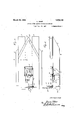
Fig. 1, is a plan view of a ship or boat constructed in accordance with my improvements with one of the hull or hull members and one connecting deck being shown.
Fig. 2, is a side elevation thereof with a portion of the inner side hull or hull member broken away to illustrate the arrangement of the spring shooting power device.
Fig. 8, is a section of one ofthe hulls or hull members on the line 3+3 of Fig, 1.
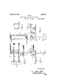
Fig. 4, is an enlarged fragmentary plan view of the spring shooting powerdevice.
Fig. 5, is an end' view'thereof.
Fig. 6, is a front elevation ofthe same.
In carrying out my inventionas herein embodied/land 8 represents the hulls or hull member of any desirable size and configuration, but preferably rectangular in cross section as shownin Fig. 3 with both the bow and stern of each hull member inclined upwardly and outwardly from the lower portions to provide the desiredoverhang. From the bottom wall of each hull member projects a fin 9 extendinglongitudinally of the hull member and substantially the full length thereof. 'lhe-completeshipv thus has a fin on both the board and starboard sides which will reduce to a minimum the rolling action of a ship because of the contact surfaces of said fins in the water.
The hull members 7 and 8 are suitably connected by a deck 10. or equivalent structure,
and above said deck at the bow of the ship may be placed a water shed 11 in the form of a wall or shroud concavo-conven in cross section with the "concavity out-board This -water shed extends about the entire bow of the ship so that waves striking the same head on will be bafiled or deflected so as to fall back without entering the ship.
At some suitable place on the ship is mounted a prime mover in the form of a motor of engine 12 provided with a shaft 13 on one end of which is mounted a sprocket wheel 14 or an equivalent to be engaged by a chain 15 or other power transmission medium, said chain running over another sprocket wheel 16 mounted on the shaft 17. The sprocket wheel is loosely mounted on said shaft but may be connected therewith for revolving the latter by means of a suitable clutch 18, and said shaft carries a number of radial arms 19 suitably spaced apart and po sitioned at different angles about said shaft. On the outer ends of the arms are mounted rollers 20 for'contact with the forward surfaces of the levers 21, 22, 23 of the standards 24, 25 and 26 journalled on a shaft 24 so will engage the standard above the hinge joined in order to maintain them in parallelism when moving rearwardly for producing the necessary force in propelling the ship forward but'which will swing at an angle to the standard when the latter is moving forwardly so that the blade or pedal is feathered and will pass through the water with a minimum friction.
Should it become necessary to reverse the usual travel of the ship so as to move astern,
the sprocket wheel 16 is released from the shaft 17 through the medium of the clutch 18 and the clutch 31' then operated to connect the bevel gear 32 to the shaft 13, thus causing the power to be transmitted to a bevel gear 33 mounted on one end of a shaft 34, the latter carrying at its power end a pulley 35 or its equivalent over which runs a belt 36 also running over a pulley 37 on the shaft of the air propeller 38.
The ship is steered in the usual manner by a rudder 39.
In actual practice, a space or well is left between the hull members at or adjacent the stern of the ship in which the spring actuated blades are located so that at all times they are practically protected from the pounding of the sea.
Of course I do not wish to be' limited to the exact details of construction as herein shown, as these may be varied within the limits of the appended claims without departing from the spirit of my invention.
Having thus fully described my invention, what I claim as new and useful is:
1. A spring power marine propulsion device comprising, in combination, a hull having after portions spaced apart, a pair of parallel transverse shafts between the spaced h-ull portions, standards independently rotatable on one shaft, levers carried by said standards, springs to actuate said standards in one direction through the levers, blades hinged to the outer free ends of the standards to present flat surfaces to the'water when moving astern and to feather when moving forward, radial arms fixed to the other shaft at different angles for co-operation with the levers to successively actuate the blade standards in the other direction and placing the springs under tension, an air anchored and the other end connected with a lever, arms fixed to the other shaft in spaced relation longitudinally of said shaft -whereby each coacts with a separate lever and also spaced circumferentially so as to progressively actuate the blades in one direction against the actions of the springs, and means to revolve the shaft on which said arms are mounted.
In testimony whereof, I have hereunto aflixed my signature.
LOUIS SHER.
Priority Applications (1)
| Application Number | Priority Date | Filing Date | Title |
|---|---|---|---|
| US234984A US1663143A (en) | 1927-11-22 | 1927-11-22 | Spring-power marine propulsion device |
Applications Claiming Priority (1)
| Application Number | Priority Date | Filing Date | Title |
|---|---|---|---|
| US234984A US1663143A (en) | 1927-11-22 | 1927-11-22 | Spring-power marine propulsion device |
Publications (1)
| Publication Number | Publication Date |
|---|---|
| US1663143A true US1663143A (en) | 1928-03-20 |
Family
ID=22883580
Family Applications (1)
| Application Number | Title | Priority Date | Filing Date |
|---|---|---|---|
| US234984A Expired - Lifetime US1663143A (en) | 1927-11-22 | 1927-11-22 | Spring-power marine propulsion device |
Country Status (1)
| Country | Link |
|---|---|
| US (1) | US1663143A (en) |
-
1927
- 1927-11-22 US US234984A patent/US1663143A/en not_active Expired - Lifetime
Similar Documents
| Publication | Publication Date | Title |
|---|---|---|
| US1663143A (en) | Spring-power marine propulsion device | |
| US2048339A (en) | Boat and means of propelling boats | |
| US1711726A (en) | Water plane | |
| US9856002B1 (en) | Watercraft with minimal water displacement | |
| US1316762A (en) | bigelow | |
| US2370318A (en) | Displacement-hydroplane boat | |
| US1888443A (en) | Water craft | |
| US2382126A (en) | Lifeboat | |
| US355682A (en) | gowles | |
| US1155654A (en) | Ship-propeller. | |
| US255599A (en) | William coppin | |
| US1570961A (en) | Hull for vessels | |
| US2303437A (en) | Means for the propulsion of ships | |
| US1134670A (en) | Ship-propeller. | |
| US1407410A (en) | Toy boat | |
| CN106314737B (en) | The new compound electric plating propulsion of warship binary | |
| SU12208A1 (en) | Screw propulsion for motor boat supported by two cylindrical floats | |
| SU426904A1 (en) | HYDROFOIL | |
| US1670622A (en) | Boat | |
| US1905162A (en) | Stern paddle-wheel propulsion mechanism for boats | |
| US1569392A (en) | Sea car | |
| US1824016A (en) | Propulsion mechanism | |
| US1593526A (en) | Means of propulsion for ships | |
| US362556A (en) | Marine propulsion | |
| TAGGART | Novel marine propulsion devices |