US1663138A - Switch-operating mechanism - Google Patents
Switch-operating mechanism Download PDFInfo
- Publication number
- US1663138A US1663138A US688903A US68890324A US1663138A US 1663138 A US1663138 A US 1663138A US 688903 A US688903 A US 688903A US 68890324 A US68890324 A US 68890324A US 1663138 A US1663138 A US 1663138A
- Authority
- US
- United States
- Prior art keywords
- switch
- door
- operating mechanism
- bar
- fuse
- Prior art date
- Legal status (The legal status is an assumption and is not a legal conclusion. Google has not performed a legal analysis and makes no representation as to the accuracy of the status listed.)
- Expired - Lifetime
Links
- 230000004048 modification Effects 0.000 description 2
- 238000012986 modification Methods 0.000 description 2
- 238000010276 construction Methods 0.000 description 1
- 238000004519 manufacturing process Methods 0.000 description 1
- 239000002184 metal Substances 0.000 description 1
- XLYOFNOQVPJJNP-UHFFFAOYSA-N water Substances O XLYOFNOQVPJJNP-UHFFFAOYSA-N 0.000 description 1
Images
Classifications
-
- H—ELECTRICITY
- H01—ELECTRIC ELEMENTS
- H01H—ELECTRIC SWITCHES; RELAYS; SELECTORS; EMERGENCY PROTECTIVE DEVICES
- H01H9/00—Details of switching devices, not covered by groups H01H1/00 - H01H7/00
- H01H9/20—Interlocking, locking, or latching mechanisms
- H01H9/22—Interlocking, locking, or latching mechanisms for interlocking between casing, cover, or protective shutter and mechanism for operating contacts
Definitions
- This invention relates to a switch operating mechanism and its object is to provide means whereby one of two circuits may be used at a time.
- This apparatus is especially intended to operate in connection with household appliances where a stove and the water heater, or some other apparatus oi that kind, is to be used, where one only is operated at a time.
- the apparatus is provided with an interlocking mechanism which makes it possible to engage or disengage one switch without engaging the other.
- Fig. 1 is a front elevation ot the switch operating mechanism, the switch operating knobs being removed therefrom.
- Fig. 2 is a sectional view on the line 6-6, Fig. 1.
- Fig. 3 is a view in elevation of the back of the front plate of the switch casing.
- the numeral 35 indicates a shallow metal box within which the switch plugs 36 and a fuse plug 48 is installed; each switch, of which there are two, having an operating handle as indicated at 41, 42, and each switch has Contact plates 38, 39, which are connected by knife blades 40, pivotally mounted to be disengaged or engaged with said contacts by the levers 41 and 42.
- the front of the box is closed by the plate 43, which plate has a small door 50 through which the fuse can be replaced, secured to the front by the hinge 51.
- the door also has a hook 52 under which the bar 46 may pass to prevent the opening of the door when the switches are in the on position.
- a plate 47 serves to prevent the door from moving inwardly further than it should.
- Pivotally mounted on a pin 45 is a bar 44, which bar carries another bar 46 at right angles thereto, to engage the hook 52 to prevent the door 'from being opened.
- the pivot for supporting the bar 44 has a square head, as shown in Fig. l, to enable it to be released from the door whenever it is desired to open the latter, in which event the i'use to be replaced through said door will be disconnected as indicated by the lower words Oil and On in Fig. 1, and a bar 44 also prevents more than one switch from being placed in the on position at one time.L
- the upper switch may, as shown in Fig. 1, be operated to the on or ofi position at will, but it' the lower switch is operated to the on position, it will lock the door 50, threw the upper switch to the oii position, and the door can only be unlocked by shitting the upper lever or by turning the pivot 45 with a suitable key, in which event the lower switch will be thrown to the oii position.
- Switch operating mechanism comprising a casing, a cover plate lfor said casing, a pair of electric switches having insulating bases mounted in said casing and levers tor operating said switches, a pivoted bar mounted on said cover plate and adapted to bear on said levers-whereby the closing of one switch will open the other, but the movement of said pivoted bar independently will operate but one oit said switches at a time, a hinged door in said cover plate. a lug on said door adapted to be engaged by an arm on said pivoted bar to lock said door when one ot said switches is closed, and means t-o operate said pivoted bar independently of said switch levers.
Landscapes
- Switch Cases, Indication, And Locking (AREA)
Description
March 2o, 192s. 1,663,138
. C. F. PARKER SWITH OPERATING MECHANISM Filed Jan.28, 1924 Patented Mar. 20, 1928.
UNITED STATES CHARLES F. PARKER, OF SAN FRANCISCO, CALIFORNIA, ASSIGNOR TO WESTERN SAFETY PATENT OFFICE.
MANUFACTURING COMPANY, INC., A CORPORATION OF CALIFORNIA.
SWITCH-OPERATING MECHANISM.
Application led January 28, 1924. Serial No. 688,903.
This invention relates to a switch operating mechanism and its object is to provide means whereby one of two circuits may be used at a time.
It will be understood by those skilled in the art that in many places it is necessary to use only one circuit of two circuits, because of the heavy current used and because it is not desired to put in apparatus heavy enough to supply both circuits with current at one time.
This apparatus is especially intended to operate in connection with household appliances where a stove and the water heater, or some other apparatus oi that kind, is to be used, where one only is operated at a time.
The apparatus is provided with an interlocking mechanism which makes it possible to engage or disengage one switch without engaging the other.
Other objects of the invention will appear as the description proceeds.
An embodimentof the invention is shown in the accompanying drawings in which the same reference numeral is applied to the same portion throughout, but I am aware that there may be modifications thereof.
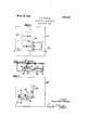
Fig. 1 is a front elevation ot the switch operating mechanism, the switch operating knobs being removed therefrom.
Fig. 2 is a sectional view on the line 6-6, Fig. 1.
Fig. 3 is a view in elevation of the back of the front plate of the switch casing.
The numeral 35 indicates a shallow metal box within which the switch plugs 36 and a fuse plug 48 is installed; each switch, of which there are two, having an operating handle as indicated at 41, 42, and each switch has Contact plates 38, 39, which are connected by knife blades 40, pivotally mounted to be disengaged or engaged with said contacts by the levers 41 and 42.
The front of the box is closed by the plate 43, which plate has a small door 50 through which the fuse can be replaced, secured to the front by the hinge 51. The door also has a hook 52 under which the bar 46 may pass to prevent the opening of the door when the switches are in the on position.
A plate 47 serves to prevent the door from moving inwardly further than it should. Pivotally mounted on a pin 45 is a bar 44, which bar carries another bar 46 at right angles thereto, to engage the hook 52 to prevent the door 'from being opened.
The pivot for supporting the bar 44, has a square head, as shown in Fig. l, to enable it to be released from the door whenever it is desired to open the latter, in which event the i'use to be replaced through said door will be disconnected as indicated by the lower words Oil and On in Fig. 1, and a bar 44 also prevents more than one switch from being placed in the on position at one time.L
From the construction above described, it
Yill be seen that the upper switch may, as shown in Fig. 1, be operated to the on or ofi position at will, but it' the lower switch is operated to the on position, it will lock the door 50, threw the upper switch to the oii position, and the door can only be unlocked by shitting the upper lever or by turning the pivot 45 with a suitable key, in which event the lower switch will be thrown to the oii position.
Only one fuse is shown in this instance and one door through which the fuse can be replaced, but another door could be provided and another fuse for the switch 37. The drawing shows the principle oi' the device.
lVhat I claim is as follows, but modifications may be made in carrying out the invention shown in the drawings and in the above particularly described form thereof, within the purview ot the invention, as deiined by the annexed claim:
Switch operating mechanism comprising a casing, a cover plate lfor said casing, a pair of electric switches having insulating bases mounted in said casing and levers tor operating said switches, a pivoted bar mounted on said cover plate and adapted to bear on said levers-whereby the closing of one switch will open the other, but the movement of said pivoted bar independently will operate but one oit said switches at a time, a hinged door in said cover plate. a lug on said door adapted to be engaged by an arm on said pivoted bar to lock said door when one ot said switches is closed, and means t-o operate said pivoted bar independently of said switch levers.
In testimony whereof I have hereunto set my hand this 31st day of December, A. D. 1923.
CHARLES F. PARKER.
Priority Applications (1)
| Application Number | Priority Date | Filing Date | Title |
|---|---|---|---|
| US688903A US1663138A (en) | 1924-01-28 | 1924-01-28 | Switch-operating mechanism |
Applications Claiming Priority (1)
| Application Number | Priority Date | Filing Date | Title |
|---|---|---|---|
| US688903A US1663138A (en) | 1924-01-28 | 1924-01-28 | Switch-operating mechanism |
Publications (1)
| Publication Number | Publication Date |
|---|---|
| US1663138A true US1663138A (en) | 1928-03-20 |
Family
ID=24766243
Family Applications (1)
| Application Number | Title | Priority Date | Filing Date |
|---|---|---|---|
| US688903A Expired - Lifetime US1663138A (en) | 1924-01-28 | 1924-01-28 | Switch-operating mechanism |
Country Status (1)
| Country | Link |
|---|---|
| US (1) | US1663138A (en) |
Cited By (1)
| Publication number | Priority date | Publication date | Assignee | Title |
|---|---|---|---|---|
| US2454803A (en) * | 1945-01-20 | 1948-11-30 | Standard Telephones Cables Ltd | Connecting base plate |
-
1924
- 1924-01-28 US US688903A patent/US1663138A/en not_active Expired - Lifetime
Cited By (1)
| Publication number | Priority date | Publication date | Assignee | Title |
|---|---|---|---|---|
| US2454803A (en) * | 1945-01-20 | 1948-11-30 | Standard Telephones Cables Ltd | Connecting base plate |
Similar Documents
| Publication | Publication Date | Title |
|---|---|---|
| US2550125A (en) | Enclosed circuit interrupter | |
| US1801228A (en) | Safety appliance for push-button stations | |
| US3122615A (en) | Interlock mechanism for enclosed switching apparatus | |
| US2260073A (en) | Enclosed circuit breaker | |
| US2263760A (en) | Enclosed circuit breaker | |
| US2163230A (en) | Front operated switch | |
| US1663138A (en) | Switch-operating mechanism | |
| US2199471A (en) | Elevator lock and switch mechanism | |
| US2053997A (en) | Combined electric switch and reserve fuse mounting | |
| US3122681A (en) | Enclosed switching apparatus | |
| US2584390A (en) | Safety cabinet switch | |
| US1483715A (en) | Switch-controlling mechanism | |
| US2215299A (en) | Electric switch enclosure | |
| US1624372A (en) | Switch lock | |
| US1310163A (en) | Knud knudsen | |
| US1915992A (en) | Safety switch construction | |
| US1604191A (en) | Externally-operated fuse and cut-out mechanism | |
| US1768245A (en) | Electrical switch apparatus | |
| US1553354A (en) | Safety-switch box | |
| US1553446A (en) | Electric switch | |
| US1490935A (en) | Interlock for safety switches | |
| US1780894A (en) | Electric switch | |
| US1224119A (en) | Safety-switch. | |
| US1677323A (en) | Switch mechanism | |
| US1852036A (en) | Safety switch box |