US1663135A - Static frequency multiplier and modulator - Google Patents
Static frequency multiplier and modulator Download PDFInfo
- Publication number
- US1663135A US1663135A US675832A US67583223A US1663135A US 1663135 A US1663135 A US 1663135A US 675832 A US675832 A US 675832A US 67583223 A US67583223 A US 67583223A US 1663135 A US1663135 A US 1663135A
- Authority
- US
- United States
- Prior art keywords
- current
- source
- winding
- circuit
- modulator
- Prior art date
- Legal status (The legal status is an assumption and is not a legal conclusion. Google has not performed a legal analysis and makes no representation as to the accuracy of the status listed.)
- Expired - Lifetime
Links
- 230000003068 static effect Effects 0.000 title description 5
- 238000004804 winding Methods 0.000 description 17
- 239000000696 magnetic material Substances 0.000 description 3
- 229920006395 saturated elastomer Polymers 0.000 description 2
- 229910052729 chemical element Inorganic materials 0.000 description 1
Images
Classifications
-
- H—ELECTRICITY
- H03—ELECTRONIC CIRCUITRY
- H03B—GENERATION OF OSCILLATIONS, DIRECTLY OR BY FREQUENCY-CHANGING, BY CIRCUITS EMPLOYING ACTIVE ELEMENTS WHICH OPERATE IN A NON-SWITCHING MANNER; GENERATION OF NOISE BY SUCH CIRCUITS
- H03B19/00—Generation of oscillations by non-regenerative frequency multiplication or division of a signal from a separate source
- H03B19/03—Generation of oscillations by non-regenerative frequency multiplication or division of a signal from a separate source using non-linear inductance
Definitions
- the present invention relates to the introduction of modulation in static frequency multipliers of the type described in my prior application Serial No. 639,709 for the purpose of producing odd harmonics by saturation with alternating current, without the use of continuous current.
- the modulation current is sent directly into the multiplier circuit without the use of. any supplementary apparatus; in the case of modulation by a telephone current, a
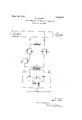
- I A source of q supplies current to the iron-core coil 3, 1n which harmonics of current are produced by the saturation ofthe core. These harmonies, or multiple frequencies, are thenpassed on to a utilization circuit, such as an antenna. Detailed arrangements for sepa rating currents of different frequency and for improving the general operation are shown in my prior application referred to above.
- Multiplier 3 is fed'with modulation cure rent through stoppers 17 and 18 constructed and adapted to impede currents ofboth the frequency so that they will not reach transformer 20, the source of the modulation current.
- a continuous (direct) voltage is introduced by storage battery 19 in such a 4 modulating current varies practically from a maximum value to zero or a low value.
- the current of harmonic frequency may moreover be rectified by the aid of mercury- I vapor rectifiers or any other cathodic rectifier devices, in such a way that it is possible to obtain by meansof static multipliers real amplifiers forcurrents having musical frequencies, in the very same manner as with three-electrode valves.
- a workable plan may betouse one multiplier of 1 kilowatt controlled by a power of 10 35 watts, which in its turn would control a multiplier of- 100 kilowatts.
- the direct current will besent into a special winding of the multiplier.
- Transformer 20 should preferably be built with .an air-gap soas to avoid saturation caused by the flowof the direct current.
- a core of magnetic material one winding only for said core, a source of high frequency currents associated with-said winding, and, a circuit shunting said winding, said circuit comprising a tuning element and a source of modulatihgcurrent;
- a single winding having'a core of magnetic material, a source of high frequency current associated therewith, a circuit'in shunt with said wind ing comprising a plurality of tuning'ele ments, a source of continuous voltage and a L source of modulating current.
- a single wind- 'ing having a core of magnetic material adapted to be saturated, a source of high source of low frequency current; a source of direct current; acoil receiving said high frequency current, said low frequency current and said direct current; and a core for said coil adapted to be magnetically saturated by said currents.
- a winding provided with a magnetic core, a source of fundamental high frequency current connected across the terminals of said winding, a shunt circuit connected across the terminals of said winding, said shunt circuit having included therein the secondary winding of a transformer and means offering high impedance to high'frequency currents, a second circuit serially includingthe primary winding of said transformer, a source of low frequency 'modulating current connected in said last capacity for compensating for the reactive current supplied by the secondary winding of said transformer.
- a winding provided with a magnetic core, a source of fundamental high frequency current connected across'the terminals of said Winding, a shunt circuit connected across the terminals of said winding, said shunt circuit having included therein a source of direct current, the secondary winding of a transformer and means offering high impedance to high frequency currents, a second circuit serially including the primary Winding of said transformer, a
Landscapes
- Physics & Mathematics (AREA)
- Nonlinear Science (AREA)
- Ac-Ac Conversion (AREA)
Description
March 2Q, 1923, L663J35 M. LATQUR STATIC FREQUENCY MULTIPLIER AND MODULATOR Filed Nov. 20, 1923 To (/izlzlzaizn Curreni,
2% gm 23 5Q 24 F To source 'o 7le fio7ze Curfeni I uve'nfoz MARIUS LATOUR Patented Mar. 20, 1928.
MARIUS LATOUB, F PARIS, FRANCE, ASSIGNOR T0 LATOUE. CORPORATION, OF JERSEY CITY, NEW JERSEY, A CORPORATION OF .DELAWARE.
STATIC FREQUENCY MULTIPLIER AND MODULATOR.
Ap'p1ication filed November 20, 1923, Serial No. 675,832, and in. France December 9, 192 2.
The present invention relates to the introduction of modulation in static frequency multipliers of the type described in my prior application Serial No. 639,709 for the purpose of producing odd harmonics by saturation with alternating current, without the use of continuous current. H
The modulation current is sent directly into the multiplier circuit without the use of. any supplementary apparatus; in the case of modulation by a telephone current, a
direct voltage is again introduced in the circuit, but this is not done with the object of obtaining the harmonic utilized in the antenna, but rather with the end in view of obtaining an undistorted speech and a more powerful modulation.
The drawing herewith illustrates one em-' bodiment of the idea underlying the invention.
I A source of q supplies current to the iron-core coil 3, 1n which harmonics of current are produced by the saturation ofthe core. These harmonies, or multiple frequencies, are thenpassed on to a utilization circuit, such as an antenna. Detailed arrangements for sepa rating currents of different frequency and for improving the general operation are shown in my prior application referred to above.
That is, there will flow n the ircuits 20, 19,.
21 and 22 of the primarycircuit of the trans-' former 20 are inserted a system of condensers and reactors 23, 24, 25, 26, the purpose of which is to cause compensation of fundamental high frequency,
fundamental frequency, and the harmonic.
manner that the instantaneous value of the the wattless or reactive current supplied by the secondaryof the transformer in the multiplier for a rather wide range of frequencies, there being thus reduced the reactive or apparent power necessary for the feeding of the multiplier.
By means of the arrangement illustrated it is feasible to realize almost complete modulation of the current of harmonic frequency 1 with only 1% of the power furnished by'65 this high frequency in the antenna circuit k or the service or working circuit.
The current of harmonic frequency may moreover be rectified by the aid of mercury- I vapor rectifiers or any other cathodic rectifier devices, in such a way that it is possible to obtain by meansof static multipliers real amplifiers forcurrents having musical frequencies, in the very same manner as with three-electrode valves.
It goes without saying that amplifier arrangements made up of several stages could be constructed by thus rectifying the high frequency current. Also the principle of reaction could be resorted to for the purpose of increasing theamplification. r
According to such principle of cascadearranged multipliers with cathode rectifiers, a workable plan may betouse one multiplier of 1 kilowatt controlled by a power of 10 35 watts, which in its turn would control a multiplier of- 100 kilowatts. The direct current will besent into a special winding of the multiplier. I J
Transformer 20 should preferably be built with .an air-gap soas to avoid saturation caused by the flowof the direct current.
Having described my invention, what .I claim is: Q
1. In a modulating system, a core of magnetic material, one winding only for said core, a source of high frequency currents associated with-said winding, and, a circuit shunting said winding, said circuit comprising a tuning element and a source of modulatihgcurrent;
2. In a modulating system, a single winding having'a core of magnetic material, a source of high frequency current associated therewith, a circuit'in shunt with said wind ing comprising a plurality of tuning'ele ments, a source of continuous voltage and a L source of modulating current.
3. In a modulating system, a single wind- 'ing having a core of magnetic material adapted to be saturated, a source of high source of low frequency current; a source of direct current; acoil receiving said high frequency current, said low frequency current and said direct current; and a core for said coil adapted to be magnetically saturated by said currents.
5. In a modulating system, a winding provided with a magnetic core, a source of fundamental high frequency current connected across the terminals of said winding, a shunt circuit connected across the terminals of said winding, said shunt circuit having included therein the secondary winding of a transformer and means offering high impedance to high'frequency currents, a second circuit serially includingthe primary winding of said transformer, a source of low frequency 'modulating current connected in said last capacity for compensating for the reactive current supplied by the secondary winding of said transformer.
6., In a modulating system, a winding provided with a magnetic core, a source of fundamental high frequency current connected across'the terminals of said Winding, a shunt circuit connected across the terminals of said winding, said shunt circuit having included therein a source of direct current, the secondary winding of a transformer and means offering high impedance to high frequency currents, a second circuit serially including the primary Winding of said transformer, a
source of low frequency modulating current connected in said last mentioned circuit, and means associated with said transformer in cluding inductance and capacity for compensating for the reactive current supplied by the secondary w nding of said transformer.
MARIUS LATOUR.
Applications Claiming Priority (1)
| Application Number | Priority Date | Filing Date | Title |
|---|---|---|---|
| FR1663135X | 1922-12-09 |
Publications (1)
| Publication Number | Publication Date |
|---|---|
| US1663135A true US1663135A (en) | 1928-03-20 |
Family
ID=9680001
Family Applications (1)
| Application Number | Title | Priority Date | Filing Date |
|---|---|---|---|
| US675832A Expired - Lifetime US1663135A (en) | 1922-12-09 | 1923-11-20 | Static frequency multiplier and modulator |
Country Status (1)
| Country | Link |
|---|---|
| US (1) | US1663135A (en) |
-
1923
- 1923-11-20 US US675832A patent/US1663135A/en not_active Expired - Lifetime
Similar Documents
| Publication | Publication Date | Title |
|---|---|---|
| US2143745A (en) | Constant potential transformer | |
| US1946308A (en) | Apparatus for radiocommunication | |
| US1663135A (en) | Static frequency multiplier and modulator | |
| US2335934A (en) | Phase modulation | |
| US2820942A (en) | Static frequency converter | |
| US2378581A (en) | Conversion of amplitude modulation to frequency modulation | |
| US1706139A (en) | Current transformer | |
| US2265113A (en) | Cyclotron | |
| US2003285A (en) | Signaling | |
| US1505085A (en) | Radio receiving apparatus | |
| US1592937A (en) | Method of and means for producing harmonics | |
| US3061804A (en) | Audio transformer | |
| US2136704A (en) | Radio circuit | |
| US1545040A (en) | Multiplying transformer | |
| US3585530A (en) | Induction coupled amplitude modulation system | |
| US2346331A (en) | Combined oscillator and reactance tube | |
| US1738346A (en) | Oscillation generator | |
| US2063307A (en) | Wave generation system | |
| GB256653A (en) | ||
| US1382877A (en) | Means for frequency transformations | |
| US2314083A (en) | Low capacity filament transformer system | |
| US1215820A (en) | Frequency-conversion system for electrical oscillations. | |
| US1755865A (en) | Coupling circuits | |
| US1645542A (en) | Circuit arrangement for high-frequency sending stations | |
| US1696233A (en) | Energizing vacuum discharge device by alternating current |