US1663133A - Safety signal - Google Patents
Safety signal Download PDFInfo
- Publication number
- US1663133A US1663133A US676834A US67683423A US1663133A US 1663133 A US1663133 A US 1663133A US 676834 A US676834 A US 676834A US 67683423 A US67683423 A US 67683423A US 1663133 A US1663133 A US 1663133A
- Authority
- US
- United States
- Prior art keywords
- signal
- light
- eye
- bulls
- central
- Prior art date
- Legal status (The legal status is an assumption and is not a legal conclusion. Google has not performed a legal analysis and makes no representation as to the accuracy of the status listed.)
- Expired - Lifetime
Links
- 241001522301 Apogonichthyoides nigripinnis Species 0.000 description 18
- 239000011521 glass Substances 0.000 description 5
- 241000239290 Araneae Species 0.000 description 4
- 239000004020 conductor Substances 0.000 description 3
- 238000010586 diagram Methods 0.000 description 2
- 239000012780 transparent material Substances 0.000 description 2
- 102100034339 Guanine nucleotide-binding protein G(olf) subunit alpha Human genes 0.000 description 1
- 101000997083 Homo sapiens Guanine nucleotide-binding protein G(olf) subunit alpha Proteins 0.000 description 1
- 241000407429 Maja Species 0.000 description 1
- 241001417524 Pomacanthidae Species 0.000 description 1
- 239000002253 acid Substances 0.000 description 1
- 244000309464 bull Species 0.000 description 1
- 238000005266 casting Methods 0.000 description 1
- 238000010276 construction Methods 0.000 description 1
- 230000005611 electricity Effects 0.000 description 1
- 238000005286 illumination Methods 0.000 description 1
- 230000008676 import Effects 0.000 description 1
- 239000000463 material Substances 0.000 description 1
- 230000002207 retinal effect Effects 0.000 description 1
- 239000004576 sand Substances 0.000 description 1
Images
Classifications
-
- B—PERFORMING OPERATIONS; TRANSPORTING
- B60—VEHICLES IN GENERAL
- B60Q—ARRANGEMENT OF SIGNALLING OR LIGHTING DEVICES, THE MOUNTING OR SUPPORTING THEREOF OR CIRCUITS THEREFOR, FOR VEHICLES IN GENERAL
- B60Q1/00—Arrangement of optical signalling or lighting devices, the mounting or supporting thereof or circuits therefor
- B60Q1/26—Arrangement of optical signalling or lighting devices, the mounting or supporting thereof or circuits therefor the devices being primarily intended to indicate the vehicle, or parts thereof, or to give signals, to other traffic
- B60Q1/34—Arrangement of optical signalling or lighting devices, the mounting or supporting thereof or circuits therefor the devices being primarily intended to indicate the vehicle, or parts thereof, or to give signals, to other traffic for indicating change of drive direction
Definitions
- This invention relates to safety signals of the character employed on automobiles for the purpose of indicating to following traflic and pedestrians an intended change inmovement, such as either an intended slowing down, stop, or right or left turn of the automobile.
- a feature of the invention is to provide a centrally disposed bulls-eye which servesv as a tail light and has the signal members lgrouped therearound in circular arrangement.
- the signal membersV are illuminable and are equipped withfchoracters indicating the intended change in movement. e. I' characters indicating right and left turns.. show up in brilliant 'white when illuminated. At a distance of'fifty feet, these characters may be easily discerned, but at a distance of 200 or 300 feet are not clearly discernible,
- This 'arrangement causes acontrasting .series of color impressions to be zproduced in the direction l from the bulls-eye intended to be indicated by the written signal and in case the latter cannot be read due to too great an interven-V ingdistance, the series of contrasting color impressions gives a strong retinal impulse which indicates the direction of the signal to the observer at a great distance therefrom.
- my invention isl to prollar plate 22 Concentrical there extends atubular barrel 24 having 'three slots 25 therein. 5
- This barrel serves the AIt is a further object of the invention to provide a sub-divided light chamber from which the signal members of 'transparent material radiate, and from which the signal members are illuminated by light rays vdirected radially and edgewise therethrough.
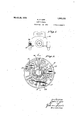
- Fig. 1 is a view showing a safety signal embodying the features of my invention in 'use upon an automobile.
- Fig. 2 is aface View of the safety signal.
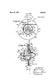
- Fig. 3 is a section taken on a plane indicated-by theline 3-3 of Fig. 2.
- Fig. 4 is a View taken as indicated by the line 4 4 of Fig.. 3, with the glass signal segments removed.
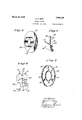
- Fig. 5 is a perspective view showing the rearward plate ofthe casing.
- Fig. 6 is a perspective view showing a dividngmember.
- v Fig. 7 is a perspective View of a spider.
- FIG. 8 is a wiring diagram.
- a central bulls-eye 11 is employed, this buls-eye having disposed concentrically therearound a circular casing 12 in which are held signal members 13, 14 and 15.
- the bulls-eye is essentially a red conoidal lens 17, Fig. 3, supported upon the forward end of a cylindrical housing 18 in which a light globe 19 is situated.
- the cylindrical housing 18 projects forwardly from a secondary cylindricalhousing member 21 which in turn projects forwardly from a disc structure 20 comprising part of theoasing 12.
- the disc structure 2O consists of an annuhaving a cylindrical hub 23, Fig. 5, pro'ecting. rearwardly therefrom. y within the cylindrical hub purpose of retaining the light socket 26'and attachment fixture 27 .through which the bulls-eye light globe 19 is supplied with electricity, and is supported concentrically withinthe housing 23 by separator members 28, Fig. 6. Three of these separator members are employed, each of them havin a plate portion 30 which extends radially netween the tubular member 24; and the cy# lindiicl housing 23, thus dividing the interior of the housing into threev light cham- Latain Abers 31, 32, and 33.
- each separator 'member 28 Outwardly extending' from the plate portion 30 of each separator 'member 28 is a radial arm 34 arranged to extend outwardly over the'face of the annu- I lar plate 22.
- the three outwardly extending arms 34 divide the plate into three separate signal member receiving areas 36, 37 and 38.
- a spider 40 On the outward edges 39 ofthe arm, a spider 40, comprised of an inner ring l 41 and an outer ring 42 interconnected by radial a1'ms43, is secured by screws 44 which thread into tapped holes 45. Asrshown at 47- in Fig.
- each separator member extends forwardly beyondthe plane of the spider 40 and the cylindrical-member 2l extends between the inner .rinorr 41 ⁇ of the spider. 40'. and the edges 46 of the pla-ne portions 30.
- the member 21 hasan inwardly extending flange v48 which extends into engagement with the outer face of the cylindrical housg 18 as indicated at 49 and has segmental l -o enings 50, 51 and 52 punched 'therein as l s own in Fig. 2, these openings being separated by webs 53 through which screws 54 may be extended ⁇ for the purpose of holding the member 21 ⁇ in place.
- green glass segments 56 a0 are he d, thus providing three, colored windows in alignment with the signal member 55 placed, these sub-central light ⁇ Into"each ⁇ o'f the spTace/swTfsegmental glass signal members placed;
- the member 15g is; oit/red plate* lass and sathefwd"Stop etched therein with acid or sand blast, as indicated at 58 in Figs. 2.
- the signal members 13 and 14 respectively are .etched on the vunder face 40. thereof with the words Left and Rite,' these members being preferably of lplate glass.
- a circular plate 31 having a central opening 62 is secured by screws 63.. 45
- the central opening 62 aligns with the tn-A bular member 24 and a small flange member 64 is'mounted thereon for holding the attachment fixture 27.
- Asub-central ⁇ sockets 67 Disposed in the late in annular arrangement, coincidingwit the L centers of the light chambers 31, 32'and 33, are Asub-central ⁇ sockets 67 which extend rearwardly vthrough the plate 61 so that connector members 68 maybe attached thereto.
- light globes are globes being separately designated'as 70, 71 and 72.
- the sockets 67 are so situated that the filaments 74 ofthe globes 70, 71 and I72 are substantially olpposite vto the inner edges of the no plate g assfsignal'members '13, 14 and 15, the light rays therefrom being directed radially outwardly through the edges of the plates as indicated by the'dotted lines 77 in f Fig. 4, theselight rays being received by 05 the etched let ring as indicated jat 58 and 13, 14 and 15 are illuminating the lettering so that it will be plainly visible for a considerable distance. ight from each sub-central globe 70, 71 or 472 will also pass directly forwardly through the green glass iny the respective openings 50, 5l'or 52.
- the light globes 19, 70,71 and 72 are controlled as indicated by the wiring diagram, Fig. 8, in which a battery is'i'ndicated at 80. One side of this batteris grounded, as indicated by 81, with t e light housing, to which housing one side 'of each light filament is electrically connected. From a: lead 82 .extending from the opposite pole of the battery 80, conductors 83, 84, 85 and 86 are respectively directed to the lights 19, 70, 71'and 72. 4The light 19 is controlled by a switch 87 fin the conductor 83, this light being continuously illuminated after sunset and serving as a tail light as well as a bea-v 'con for the signal lights.
- the light ⁇ 72' which serves for illuminating the sto signal is preferably controlled by a switc 88 in the conductor'86 which is preferably actlgrated by the brakepedal in such a.-manner ⁇ that the stop signal will' be illuminated each. f timef the brake pedal is advanced.
- the lights 70m71"costit1tinghe illuminating means for the Left and Rite signals are preferably controlled by switches 90 and '91 95 mounted on the steering wheel so as to be conveniently operated..
- a slot 94 is formed, this slot allowing ai iin shapedbeam-of...light to-be..cast Adownwardly from the globe 19 in av manner Vto illuminate the face of the license plate 'l which is preferably to be mounted below the safety signal, and which may be conveniently mounteg lupon tIlie leftward automo ie 9 ig. 1. hn
- a driver in a car fbllowingf the machlne equipped with the signal device will view the bulls-eye continuously.
- the signal member '14 and the green window 51 are illuminated .there y.
- the ap earance of a light tothe right ofthe bull s-eye will im mediately signify' to the following driver that a movement to the rightward direction' ilntended, even though he should be at such a distance behind the'lsignal that the characters therein are not clearly discernible.
- the co1nbina tion of: a colored -bulls-eye adapted to be ⁇ constantly illuminated ;a housing for .said l bulls-eye; means for illuminating said bulls-eye; signal segments of transparent material radially extendedA outward from ⁇ segments having direction indicia carried thereby; sub-central lights whereby said segments may be separately illuminated; means for confining thc rays of said sub-central lights to the proper segments; and a transparent pane' of a c olor contrastingwith that of the bulls-eye disposed between each ofthe adjacent segments and adapted to be illum- .inated with' its adjacent signal segmentby the same sub-central light illuminating -said adjacent slgnal segment so as to cause a contrasting series of color impressions to be produced in a given direction from the bullseye.
- the vehicle safety signal the combination of: aconductor conduit axially disposed in Vsaid signal; a central llight bulb provided upon the forward end of said conduit; radial walls angularly spaced about said conduit; with said conduit and said radial Walls. to provide sub-central light chambers; a dlscshaped wall provided upon said exterior Walls; ⁇ a ⁇ circumferential wall co-operating with.
- said. front wall of said exterior'walls is formed ot' transparent colored material.
Landscapes
- Engineering & Computer Science (AREA)
- Mechanical Engineering (AREA)
- Non-Portable Lighting Devices Or Systems Thereof (AREA)
- Illuminated Signs And Luminous Advertising (AREA)
- Lighting Device Outwards From Vehicle And Optical Signal (AREA)
Description
'March zo, 192s. 1,663,133
. M. P. KIRK SAFETY SIGNAL Filed Nov. 24. 1923 5 Sheets-Sheetl V1/:jf TOR:
/70/6/9/.5 l. )fr fr f n wnv ,wou/
March 20,. 1928.
M. P. KIRK SAFETY SIGNAL Filed Nov. 24. 1923 March-20,1928. y 1 1',663,133
M. P. KIRK SAFETY S I GNAL Filed Nov. 24. 1923 3 Sheets-Sheet 5 v 45 of which is interposed Patented Maia '20, 1928.
MORRIS I. KIRK, F IJOS'ANGELES, CALIFORNIA.
SAFETY SIGNAL.
Application led November 24, i923. Serial No. 876,834.
This invention relates to safety signals of the character employed on automobiles for the purpose of indicating to following traflic and pedestrians an intended change inmovement, such as either an intended slowing down, stop, or right or left turn of the automobile.
It is an object of the invention to provide a. safety signal employing right, leftand stop indications and incorporating therewith a red'bulls-eye serving as a tail light and having means for casting a beam of light upon the face of the license plate.
A feature of the invention is to provide a centrally disposed bulls-eye which servesv as a tail light and has the signal members lgrouped therearound in circular arrangement. The signal membersV are illuminable and are equipped withfchoracters indicating the intended change in movement. e. I' characters indicating right and left turns.. show up in brilliant 'white when illuminated. At a distance of'fifty feet, these characters may be easily discerned, but at a distance of 200 or 300 feet are not clearly discernible,
but the import thereof is recognized frorrr 'the positionof the illuminated portio'rlrelative to the centrally disposed bulls-eye, thus plainly indicating to a following driver that a turn is intended in the direction pointing from the` red light to the white light. The` red light serving as the ltail light is continuously visible to a following machine, therefore the appearance of another light on either side thereof` makes an intended turn immediately evident.
Another object of vide in a safety signal having a lconstantly illuminated` central bulls-eye and indicia bearing signal segments disposed about the bulls-eye which are separately illuminable to indicate a` written signal, transparent'.`
panes contrasting in lcolor with that of the bulls-eye and the vsignal segments, and each between the bulls-eye and a signal segment so as to he illuminated with 'that signal segment. This 'arrangement causes acontrasting .series of color impressions to be zproduced in the direction l from the bulls-eye intended to be indicated by the written signal and in case the latter cannot be read due to too great an interven-V ingdistance, the series of contrasting color impressions gives a strong retinal impulse which indicates the direction of the signal to the observer at a great distance therefrom..
my invention isl to prollar plate 22 Concentrical there extends atubular barrel 24 having 'three slots 25 therein. 5 This barrel serves the AIt is a further object of the invention to provide a sub-divided light chamber from which the signal members of 'transparent material radiate, and from which the signal members are illuminated by light rays vdirected radially and edgewise therethrough.
The especial advantages of the invention and further objects thereof will be made evi# dent hereinafter.
Referring to the drawings which arefor illustrative purposes only:
Fig. 1 is a view showing a safety signal embodying the features of my invention in 'use upon an automobile.
Fig. 2 is aface View of the safety signal.
Fig. 3 is a section taken on a plane indicated-by theline 3-3 of Fig. 2. I
Fig. 4 is a View taken as indicated by the line 4 4 of Fig.. 3, with the glass signal segments removed.
Fig. 5 is a perspective view showing the rearward plate ofthe casing.
Fig. 6 is a perspective view showing a dividngmember. v Fig. 7 is a perspective View of a spider.
8 is a wiring diagram. In' theforrn of thel invention shown in the drawings, a central bulls-eye 11 is employed, this buls-eye having disposed concentrically therearound a circular casing 12 in which are held signal members 13, 14 and 15. The bulls-eye is essentially a red conoidal lens 17, Fig. 3, supported upon the forward end of a cylindrical housing 18 in which a light globe 19 is situated. The cylindrical housing 18 projects forwardly from a secondary cylindricalhousing member 21 which in turn projects forwardly from a disc structure 20 comprising part of theoasing 12. l y
The disc structure 2O consists of an annuhaving a cylindrical hub 23, Fig. 5, pro'ecting. rearwardly therefrom. y within the cylindrical hub purpose of retaining the light socket 26'and attachment fixture 27 .through which the bulls-eye light globe 19 is supplied with electricity, and is supported concentrically withinthe housing 23 by separator members 28, Fig. 6. Three of these separator members are employed, each of them havin a plate portion 30 which extends radially netween the tubular member 24; and the cy# lindiicl housing 23, thus dividing the interior of the housing into threev light cham- Latain Abers 31, 32, and 33. Outwardly extending' from the plate portion 30 of each separator 'member 28 isa radial arm 34 arranged to extend outwardly over the'face of the annu- I lar plate 22. The three outwardly extending arms 34 divide the plate into three separate signal member receiving areas 36, 37 and 38. On the outward edges 39 ofthe arm, a spider 40, comprised of an inner ring l 41 and an outer ring 42 interconnected by radial a1'ms43, is secured by screws 44 which thread into tapped holes 45. Asrshown at 47- in Fig. 3, the plate por-v tion 30 of each separator member extends forwardly beyondthe plane of the spider 40 and the cylindrical-member 2l extends between the inner .rinorr 41 `of the spider. 40'. and the edges 46 of the pla-ne portions 30. The member 21 hasan inwardly extending flange v48 which extends into engagement with the outer face of the cylindrical housg 18 as indicated at 49 and has segmental l -o enings 50, 51 and 52 punched 'therein as l s own in Fig. 2, these openings being separated by webs 53 through which screws 54 may be extended `for the purpose of holding the member 21 `in place. Between the flange 48 and the outwardly disposed edges of the plate portion 30, green glass segments 56 a0 are he d, thus providing three, colored windows in alignment with the signal member 55 placed, these sub-central light `Into"each`\o'f the spTace/swTfsegmental glass signal members placed; The member 15g is; oit/red plate* lass and sathefwd"Stop etched therein with acid or sand blast, as indicated at 58 in Figs. 2. The signal members 13 and 14 respectively are .etched on the vunder face 40. thereof with the words Left and Rite,' these members being preferably of lplate glass. Across the rearward edges 60 of the plate portions 30, a circular plate 31 having a central opening 62 is secured by screws 63.. 45 The central opening 62 aligns with the tn-A bular member 24 and a small flange member 64 is'mounted thereon for holding the attachment fixture 27. Disposed in the late in annular arrangement, coincidingwit the L centers of the light chambers 31, 32'and 33, are Asub-central `sockets 67 which extend rearwardly vthrough the plate 61 so that connector members 68 maybe attached thereto. In each of the sockets 67, light globes are globes being separately designated'as 70, 71 and 72. The sockets 67 are so situated that the filaments 74 ofthe globes 70, 71 and I72 are substantially olpposite vto the inner edges of the no plate g assfsignal'members '13, 14 and 15, the light rays therefrom being directed radially outwardly through the edges of the plates as indicated by the'dotted lines 77 in f Fig. 4, theselight rays being received by 05 the etched let ring as indicated jat 58 and 13, 14 and 15 are illuminating the lettering so that it will be plainly visible for a considerable distance. ight from each sub-central globe 70, 71 or 472 will also pass directly forwardly through the green glass iny the respective openings 50, 5l'or 52. The light globes 19, 70,71 and 72 are controlled as indicated by the wiring diagram, Fig. 8, in which a battery is'i'ndicated at 80. One side of this batteris grounded, as indicated by 81, with t e light housing, to which housing one side 'of each light filament is electrically connected. From a: lead 82 .extending from the opposite pole of the battery 80, conductors 83, 84, 85 and 86 are respectively directed to the lights 19, 70, 71'and 72. 4The light 19 is controlled by a switch 87 fin the conductor 83, this light being continuously illuminated after sunset and serving as a tail light as well as a bea-v 'con for the signal lights. The light` 72' which serves for illuminating the sto signal is preferably controlled by a switc 88 in the conductor'86 which is preferably actlgrated by the brakepedal in such a.-manner` that the stop signal will' be illuminated each. f timef the brake pedal is advanced. The lights 70m71"costit1tinghe illuminating means for the Left and Rite signals are preferably controlled by switches 90 and '91 95 mounted on the steering wheel so as to be conveniently operated.. In the lower edge of the cylindrical hous- 1n 18, a slot 94is formed, this slot allowing ai iin shapedbeam-of...light to-be..cast Adownwardly from the globe 19 in av manner Vto illuminate the face of the license plate 'l which is preferably to be mounted below the safety signal, and which may be conveniently mounteg lupon tIlie leftward automo ie 9 ig. 1. hn
TheJbulls-eye serving asa tail hght\is`at all times visible and is continuousl illuminated at night. A driver in a car fbllowingf the machlne equipped with the signal device will view the bulls-eye continuously. When an intended turn to the right is indicated by closing the Aswitch 91, Flg. 8, the signal member '14 and the green window 51 are illuminated .there y. The ap earance of a light tothe right ofthe bull s-eye will im mediately signify' to the following driver that a movement to the rightward direction' ilntended, even though he should be at such a distance behind the'lsignal that the characters therein are not clearly discernible. flhe operation ofthe switch 90 will cause illumination of ajsi al member 13 vand the green window 50, w ich is leftward with respect to the bulls-eye 17 and will theefore indlcate -an intended leftward movementeven thugh the characters thereof cannot be made ou Y The` stop signal bein disposed beneath the tail of redcolor and light will,
and said bulls-eye,
.pact in I said bulls-cye; said red illuminated area to caution by the-following driver, thus. it is not entirely necessary f that the word sto be noticeable in order to impart the inten ed signal. ,The construction employed is articularly valuable'in that a. sutliciently large a central light iousing is employed from which the signal elements radiate. The light' housing is of small size and therefore coinform. The .utilization of the tail light as a beacon or continuously visible point from which to extend the turn signals is also a feature which contributes to the effectiveness of the device as a means for properly imparting a traflic signal and therefore `for reducing frequency of accidents.
I claim as my invention: A'
1. In a vehicle safety signal, the co1nbina. tion of: a colored -bulls-eye adapted to be\ constantly illuminated ;a housing for .said l bulls-eye; means for illuminating said bulls-eye; signal segments of transparent material radially extendedA outward from `segments having direction indicia carried thereby; sub-central lights whereby said segments may be separately illuminated; means for confining thc rays of said sub-central lights to the proper segments; and a transparent pane' of a c olor contrastingwith that of the bulls-eye disposed between each ofthe adjacent segments and adapted to be illum- .inated with' its adjacent signal segmentby the same sub-central light illuminating -said adjacent slgnal segment so as to cause a contrasting series of color impressions to be produced in a given direction from the bullseye.
2. In.the vehicle safety signal, the combination of: aconductor conduit axially disposed in Vsaid signal; a central llight bulb provided upon the forward end of said conduit; radial walls angularly spaced about said conduit; with said conduit and said radial Walls. to provide sub-central light chambers; a dlscshaped wall provided upon said exterior Walls;`a `circumferential wall co-operating with. said disc shaped wall and with radially extending portions of said radial walls to form shallow signal element pockets, there being' openings provided between the inner exterior walls co-operating edges .of said pockets and corresponding -sub- 4 centr-al light chambers; lat signal elements disposed in said pockets with the inner edges thereof in said openings; light bulbs 'disposed in said sub-central light' chambers: bulls-eye walls connecting with thev front wall of said exteriorl walls and forming a light chamber about said central bulb; a bullsLeye closing the front end of said bullseye light chamber; means ,for constantly ilhuninating said central bulb; and means for separately lighting' said subcentral bulbs. 3. 'A combination as in claim 2 inwhich said. front wall of said exterior'walls is formed ot' transparent colored material.
ln testimony whereof, I have hereunto set my hand at. Los Angeles, California, this 15th day of November, 1923.
Priority Applications (1)
| Application Number | Priority Date | Filing Date | Title |
|---|---|---|---|
| US676834A US1663133A (en) | 1923-11-24 | 1923-11-24 | Safety signal |
Applications Claiming Priority (1)
| Application Number | Priority Date | Filing Date | Title |
|---|---|---|---|
| US676834A US1663133A (en) | 1923-11-24 | 1923-11-24 | Safety signal |
Publications (1)
| Publication Number | Publication Date |
|---|---|
| US1663133A true US1663133A (en) | 1928-03-20 |
Family
ID=24716199
Family Applications (1)
| Application Number | Title | Priority Date | Filing Date |
|---|---|---|---|
| US676834A Expired - Lifetime US1663133A (en) | 1923-11-24 | 1923-11-24 | Safety signal |
Country Status (1)
| Country | Link |
|---|---|
| US (1) | US1663133A (en) |
Cited By (1)
| Publication number | Priority date | Publication date | Assignee | Title |
|---|---|---|---|---|
| US5388035A (en) * | 1993-07-23 | 1995-02-07 | Federal-Mogul Corporation | Automotive marker lamp |
-
1923
- 1923-11-24 US US676834A patent/US1663133A/en not_active Expired - Lifetime
Cited By (1)
| Publication number | Priority date | Publication date | Assignee | Title |
|---|---|---|---|---|
| US5388035A (en) * | 1993-07-23 | 1995-02-07 | Federal-Mogul Corporation | Automotive marker lamp |
Similar Documents
| Publication | Publication Date | Title |
|---|---|---|
| US1586242A (en) | Signaling lamp, suitable for day and night use, chiefly on motor cars | |
| US4214168A (en) | Traffic light and motor vehicle taillight lenses | |
| US1663133A (en) | Safety signal | |
| US2084252A (en) | Automobile indicator | |
| US2304861A (en) | Blackout means for automobile lamps | |
| US2339687A (en) | Direction signal device | |
| US3229250A (en) | Means for signalling the possibility of overtaking | |
| US2323793A (en) | Traffic signaling mechanism | |
| US1740588A (en) | Illuminating means | |
| US1468830A (en) | Signal for automotive vehicles | |
| US1828233A (en) | Lens | |
| US2005761A (en) | Combination back-up and tail light | |
| US1848685A (en) | Vehicle direction signal | |
| US1351635A (en) | Automobile direction-signal | |
| US1740777A (en) | Automobile signaling device | |
| US2096952A (en) | Traffic signal | |
| US2152789A (en) | Signaling device | |
| US1617423A (en) | Vehicle lamp | |
| US1998157A (en) | Automobile signal light | |
| US3032641A (en) | Fog light for illuminating airport runways | |
| US1702429A (en) | Signal lamp for motor vehicles | |
| US1343899A (en) | Signal-lamp | |
| US1552380A (en) | Signal system for vehicles | |
| US1528332A (en) | Automobile light | |
| US1611706A (en) | Night turning signal for vehicles |