US1663115A - Baker's oven - Google Patents
Baker's oven Download PDFInfo
- Publication number
- US1663115A US1663115A US661064A US66106423A US1663115A US 1663115 A US1663115 A US 1663115A US 661064 A US661064 A US 661064A US 66106423 A US66106423 A US 66106423A US 1663115 A US1663115 A US 1663115A
- Authority
- US
- United States
- Prior art keywords
- chamber
- oven
- burners
- baking
- baking chamber
- Prior art date
- Legal status (The legal status is an assumption and is not a legal conclusion. Google has not performed a legal analysis and makes no representation as to the accuracy of the status listed.)
- Expired - Lifetime
Links
- 239000000446 fuel Substances 0.000 description 19
- 238000010438 heat treatment Methods 0.000 description 16
- 230000009471 action Effects 0.000 description 6
- 238000010276 construction Methods 0.000 description 5
- 235000008429 bread Nutrition 0.000 description 4
- 239000000463 material Substances 0.000 description 4
- 239000011810 insulating material Substances 0.000 description 3
- 230000003405 preventing effect Effects 0.000 description 3
- 238000001816 cooling Methods 0.000 description 2
- 230000008878 coupling Effects 0.000 description 2
- 238000010168 coupling process Methods 0.000 description 2
- 238000005859 coupling reaction Methods 0.000 description 2
- 230000009467 reduction Effects 0.000 description 2
- 230000000630 rising effect Effects 0.000 description 2
- LFQSCWFLJHTTHZ-UHFFFAOYSA-N Ethanol Chemical compound CCO LFQSCWFLJHTTHZ-UHFFFAOYSA-N 0.000 description 1
- 229910000746 Structural steel Inorganic materials 0.000 description 1
- 230000008901 benefit Effects 0.000 description 1
- NEHMKBQYUWJMIP-UHFFFAOYSA-N chloromethane Chemical compound ClC NEHMKBQYUWJMIP-UHFFFAOYSA-N 0.000 description 1
- 230000003247 decreasing effect Effects 0.000 description 1
- 239000000796 flavoring agent Substances 0.000 description 1
- 235000019634 flavors Nutrition 0.000 description 1
- 239000008246 gaseous mixture Substances 0.000 description 1
- 230000006872 improvement Effects 0.000 description 1
- 238000007689 inspection Methods 0.000 description 1
- 239000002184 metal Substances 0.000 description 1
- 229910052751 metal Inorganic materials 0.000 description 1
- 238000000034 method Methods 0.000 description 1
- 239000000203 mixture Substances 0.000 description 1
- 229920006395 saturated elastomer Polymers 0.000 description 1
- 230000000153 supplemental effect Effects 0.000 description 1
- 239000002699 waste material Substances 0.000 description 1
Images
Classifications
-
- A—HUMAN NECESSITIES
- A21—BAKING; EDIBLE DOUGHS
- A21B—BAKERS' OVENS; MACHINES OR EQUIPMENT FOR BAKING
- A21B1/00—Bakers' ovens
- A21B1/40—Bakers' ovens characterised by the means for regulating the temperature
Definitions
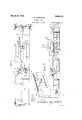
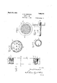
- Fig. 1 is a plan of an oven embodying the 60 an' oven, and an improved method of operatpresent invention. J ing the same, whereby the efliciency of the Fig. 2 is a side elevation; oven will be materially increased and an Fig. 3 is a longitudinal vertical section, on improved product obtain d, an enlarged scale, of portions of the oven.
- Fig. 4 is an elevationof the delivery end 05 use with ovens of the type employingan of the oven.
- endless conveyor for transporting the prod- Fi 5 is a sectional view, substantially on ucts, for example, bread, through the oven, the line 5'-5 of Figure 1, on an enlarged and one ot the objects of the invention is to scale.
- Fig. 6 is an enlarged view, partly in-seccomposed of a series of similar sections tion, of one of the-heat exchangers. which may be readily assembled to that an Fig. 7 is an elevation of one of'the burners oven of'any desired length may be initially detached, partly inhorizontal section. built or' the length of the oven increased or Fig. 8 is an elevational detail of a part of 20 decreased, if desired. the b rner. p v Q
- Fig. 9 1s an elevation, partly in section, of
- Fig. 10. is a section on the line 10-10 of the products during the baking operation, and any vapor caused by the introduction of 1g- 5 steam or moisture to the baking chamber
- Fig. 11 1s a section on the line '1111 of collects in the upper part of the baking Fig- 6.
- the pres- Fig. 12 is a section, on an enlarged scale, sure thereof tends to.carry it toward the substantially on the line 12-12 of Figure 7.
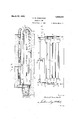
- the mproved 35 tion of the oven necessarily exerts pressure e n f rmed of a series of sections, each on the productsbeing baked, and, to some includ ng outer and inner side walls 1, 2, and degree, retards the expansive action or rising an. intermediate body 3 of suitable heat insuof the loaf under the action of the. baking l ting materia
- The. walls 1, 2, are preferheat. ably formed of sheet metal plates suitably One of the particular objects of the inven- Strengthened by angle iron uprights 4, 5,
- tion is to provide means whereby the prodi h m y Serve as means eonneetmg t b i b k d ill b li d'f ad o1n1ngsect1ons so that a baking chamber cessive pressure of suchvapor, so that the ff any desired length may be readily pro loaf may freely expand to the maximum dee
- the sectlQns ulllts m y be O y gree and a-lighter' product be obtained than des red length, suitably aligned and secured is possible ith th th d d b th to give a continuous oven of the desired pro-' ortions.
- the baking chamber has a metalbottom 6
- a further object of the invention is to uti- I lize the heated vaporwithdrawn from the nd top 7 supported by suitable an is bar 0 baking chamber as a means for h i g from the inner-sideplates 2, and t e heat -1 0 the gaseous fuel which is upplied to the insulating body 3 extends ove the ,plfi e oven burners. 7 and beneath the bottom plate 6 so t, at the The invention will be hereinafter de-. entire chamber is surrounded by such mate- 55 scribed in detail in connection with the acrial.
- the conveyor 9 extends throughout the "length of the baking chamber, and may project, and is here so shown, from the ends of said chamber. At its receiving end the conveyor is supported on sprockets 13 carried by a shaft 10 extending transversely across the end of the oven, 3, the oven casing and the body of heat insulating material is extended beneath and about the sides and in front of the conveyor supporting sprockets, so that, when constructed. with the ends of the conveyor projecting, these parts are encased, except for a relatively small space which is provided to receive the products to be transported into the baking chamber. As shown, the'casing and insulating body extend a considerable distance above the axis of the shaft 10 and practically to the horizontal plane ofthe upper run of the conveyor.
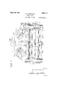
- the gears 17, 17' are driven by pinions 18, 18, on a shaft 19, which is also provided with a worm wheel 20 that is driven by a worm shaft 21 actuated by a suitable motor 22 that is shown as supported.
- a conduit 25 (see Figs 1 and 5) is pro-.
- conduit for driving each vided beneath the bottom of the oven cham-" her, which conduit extends throughout the length of the chamber and is provided,'at suitable intervals in its top wall, with inlet apertures adapted to be controlled by dampers 26, the handles 27 of which extend through a side wall of the oven.
- the conduit communicates with the lower member ofa flue or conduit 28, which, as here shown, extends upward along one side of the oven, between the walls 1, 2, thereof, and inward over the top plate 7, and communicates with a conduit 29 having two branches, which communicate, respectively, with the casings of two heat exchangers 30, 1, by which fuel (preferably gaseous) employed for heating the oven is preliminarily heated.
- the two heat exchangers are of similar construction, each comprising a casing having therein a series of longitudinally exers, and communicating, at their ends, with chambers formed in the heads 33, 34.
- Each of said casings is provided with an outlet with which connects one member of a suction pipe 36', that, in turn, communicates with the casing of a suction: fan 37, driven by a suitable motor 38.1-A stack 39, connected to the fan casing, is provided for carrying away the heated air and vapor withdrawn by the fan from the baking chamber through the conduits 25, 28, 29, and the spaces within the casings 30,31, about the series of tubes therein.
- each casing 30,31 is connected with a suitable pressure pump 40, actuated by a motor 41, and the said pumps are, respectively, connected by pipes 41' with two mains 42, 43, which-may, as here shown, extend longitudinally along one side of the oven, being embedded in thebody of heat gas supply pipe 44 is connected to the inlet end of the casing 30, while the casing 31 is provided, at its correspondingend, with an air inlet.
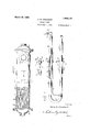
- pipes 49 leading tothe several 'ing longitudinally of the casing and secured extending across have their peripheries slitted to provide a series of separated blades which are slightly bent orbowed, so that portions thereof projeict beyond the plane of the body of the p ate.
- the several plates are so related that the currents ofair and gas passing through the casing 46 are thoroughly intermingled.
- burners are divided into several groups, each group being connected with one of the mixing chambers- To avoid confusion in the drawshown, but it will be understood that .as
- the burners extend substantially across the baking chamber (see Fig. 5), and each is of U form, the one leg of the burner being connected to the combustible fuel supply pipe, and, the other end being closed, preferably, as shown, by a removable plug.
- the two parallel sections ofthe burner are in substantially the same horizontal plane, and each is provided with a series of perforations 61, at which the combustible fuel is ignited.
- apertures or burner openings 61 are only providedin the portions of the:tubes which face toward the ends of the baking chamber.
- the supply of combustible fuel to each burner is independently controlled by a valve 62.
- each preferably, consists of three sections, namely, end sections 63, 64, and an intermediate, bowed section 65.
- the several sections are eonnected in any suitable manner, as by sleeve members 66, 67, which are provided. with lugs 68 connected by suitable bolts 69.
- a slot' 67 is formed in the" sleeve ,67 in alignment with the burner openings 61;
- This substantially U-shaped burner is advanta-- geous for the reason that it will give a uniform temperature throughout the width of the baking chamber.
- the average of the two temperatures of the flame adjacent the U or return bend will be the same as the average temperatures at the inlet end and the blank end of the burner, and this is a distinct advantage .over a straight burner, in which there is variation in temperature from the inlet end to the blank end.
- a small tube 70 is provided, Such tube leads from the burner section 63 to a point near the inner end of the opposite stra' ht member of the burner, and a'pilot light i maintained at its free end. Thiswill serve to ensure ignition of the combustible gas issuing from the adjacent straight member of the burner in case the same should be extinguished from any cause, as, for example, by a reduction of pressure in the burner by reason of the ad-.
- 'a' plate 80 which extends substantially throughout the length of the baking chamber and is connected with-the side plates thereof at suitable intervals, so that spaces 81 are provided through which the heat of the burners'may pass downwardly and have free access to the articles on the upper run of the conveyor.
- This late or shield 80 over the top of the baking chamber, effectively separates the generated vapors from the products under treatment from the flame of the burners, and serves to confine the vapors'about and above the material being baked or treated. Furthermore, the shield 80 tends to confine the heat and ensures a uniform temperature throughout the entire area in which the material, such as loaves of bread, is being treated.
- This provides a substantially continuous Wall extending above the lower series of burners 60. which will transm t heat therefrom to the articles on the con veyor.
- the plate 80 acts to preacter to which the present invention relates vent the vapor, generated by the action of y heatv on the moist dough, from directly passinginto contact with the upper set of burners where it would have a tendency to smother the flame; and also serves to maintain a body of such vapor about the articles on the conveyor.
- the vapor produced during the baking 0 eration contains a considerable percentage of alcohol, the action of which on the loaf .to a considerable degree determines the color of the crust and imparts a desirable flavor to the body of the loaf.
- loaves of bread for example, are enveloped in a saturated vapor during the baking operation which results in giving the desired color to the baked loaf. If the shield or baflie 80 is not employed and the pressure of the generated vapor on the loaves reduced by drawing the vapor downward bethe baking operation.
- each of said casings being preferably provided with, baffles 30, which cause said air and vapor to pursue'acircuitous course in traveling through the casings, thus imparting a maximum amount of heat to the air or gas passing through the tubes 32.
- the pumps or blowers 40 maintain a uniform pressure upon the air and gas supplied to the mains which communicate with the several mixers, and as thef'supply of gas to each group ofburners, as well as that to each individual burner of a group can be easily controlled, the temperature of the baking chamber may be maintained at any desired degree.
- suitable inspection windows 90 are provided at various points in the walls of the oven.
- the construction of scribed, the pilot lig the oven frame is such that any desired number of units or sections may be readily assembled to provide a baking chamber of the required length, and the gearing employed for driving the conveyor is arranged in a very compact manner closely adjacent the sides of the oven, so that a minimum amount of floor space is required.
- Each burner may have a relatively short pilot light section 90 extending into it from a header 91 on the outside of the oven, said pilot light section extending, for example, as a far as the first opening 61. With such arrangement, any burner may be extinguished without affecting said pilot sections, and quickly ignite from such pilot when the flow of fuel is resumed.
- the pilot lights are effective in preventing undesirable cooling of the oven during between baking periods.
- dets may be operative for indefinite periods of time and when at the termination of a baking period the supply of gas to the burners is .cut oil, by manipulation ofthe valves 51- or 62, the heat derived from the pilot lights will be sufficient to prevent material reduction of the vtemperature in the baking chamber. This avoids the delay commonly incident to restoringthe desired baking temperature at v the beginning of a succeeding baking period,
- Thepilotlights will, of course, operate to relight the burners following a resump its travel through the oven chamber, and, of
- the action of the suction fan may be varied or discontinued to su t different condltlons.
- a substantially horizontalsupport for articles to be baked within the chamber means for heating the chamber including burners arranged above said support, a stationary horizontal bafile positioned between the article support and the burners above such support, and adapted ,to maintain a body of vapor generated in the baking operation in contact with the articles bein baked while shielding said burners from suc vapor, and means for relieving the articles being baked from excessive pressure of said vapor.
- a bakers oven the combination of a chamber, a substantially horizontal support for articles to be baked within the chamber, means for heating the chamber including burners arranged above said support, a stationary bafliearranged between said support and burners and adapted to maintain a body of vapor generated in the baking operation in contact with the articles being baked while shielding said burners from said vapor, and means for relieving the articles being baked from excessive pressure of said vapor by creating a suction downward through the chamber.
- a bakers oven the combinationof, a baking chamber, gaseous fuel burners for heating said chamber, means for relieving the articles being baked of excessive pressure of vapor gener' bed in the baking chamber,
- a baking chamber means for heating said chamber, means for supporting within the chamber articles to be baked, means for maintaining above and in contact with the articles'being baked a body of vapor generated from said articles by the baklng operation, -a conduit communicating with the interior of the chamber below the horizontal .plane of the said supporting means, and generatedmeans for withdrawing vapor from the articles being baked downward aboutthe articles and through said conduit, whereby all of the articles being baked in the chamber are subjected to a vapor of substantially uniform character and pressure.
- a conduit extending longitudinally of and below the bottom of the chamber and communicating with the chamber at a plurality of points, and means for creating suetion through the conduit to withdraw heated air and vapor from the chamber.
- bakin chamber gaseous fuel burners within said 0 amber, means for supplying a combustible gaseous mixture under pressure to the burners, means for preliminarily heating the elements of said mixture includin a heat exchanger on top of the oven, an means for conducting heated air and vapor from the oven chamber to said heat exchanger.
- a bakers oven the combination of a baking chamber, gaseous'fuel burners within said chamber, means for supplying fuel under pressure to the burners, and means for withdrawing heated air and vapor from the chamberv and utilizing it to preliminarily heat the gaseous fuel.
- a bakers oven the combination of a baking chamber, a luralit'y of gaseous fuel burners or heating t 1e baking chamber, mains for ail-and gas respectively, a mixer associated with each roup of bumers and connected to both sai ma1ns, means for supplying air and gas to said mams, re.- speetively under pressure, and means for withdrawing heated air. and vapor from the oven chamber and using'it to heat the air and gas before entering saidimains.
- baking chamber having a conduit extending longitudinally of the bottom thereof and provided with a plurality of inlets communicatin with the chamber, an outlet be-. ing providbd in the top of the oven, a transverse conduit connecting the longitudinal conduit with said outlet, a suction'fan connected with the outlet, gaseous fuel burners for heating the oven chamber, and means for preliminarily heating the gas supplied to the burners including a heat exchanger arranged in the connection between saidoutlet and suction fan.
- a bakers oven the combination of a baking chamber, gaseous fuel burners for heating said chamber, two casings each'provided with a series of longitudinally extend-- 14.
- a baker s oven the combination of a baking chamber, a conduit extending longitudinally of the bottom of said chamber and communicating therewith, an endless conyeyor travelling longitudinally ofthe baklngachamber, burners within the chamber above and below the upper section of the etween the upper serles of burners and the conveyor, anda.
- a baflie plate suction fan arranged outside the oven and connectedto said conduit, for the purpose described.
- a burner within the baking chamber above the path of the articles to be baked through' the chamber, means arranged'beneath the burner and above and out of contact with the articles being baked, adapted to maintain a'body of vapor, generated from the articles being baked,. in contact with the upper surfaces of said articles and to prevent such vapor passing directlyintocontact with the burner, and means for causing said vapor -to pass downward through the baking chamher to relieve the articles .being baked from excessive pressure by said vapor;- I
- a bakers oven the combination of a baking chamber, means for supporting a series of articles to be baked within and fiioving'them through the baking chamber, burners within the baking chamber above and below the path of the articles to be baked through the chamber, means for pre venting vapor generated during the baking operation from passing directly upward in-' to contact with the burner above the articles being baked, and means for causing said vapors to move downward through the baking chamber.
- a bakers oven the combination of a baking chamber, means for supporting a series of articles to be baked within. and moving them through the baking chamber, burners within the baking chamber above and below the path of the articles to be baked through the chamber, means for causing preventing it from passing directly upward into contact with the upper burner.
- each burner comprising two sectional, parallel laterally perforated members, one of which extendsthrough the chamber wall and the other of which is closed at one end, and an intermediate curved section, and means outside the transversely of the baking chamber and ar-- ranged in groups which are spaced apart longitudinally of the chamber to provide a plurality of heating zones, and a thermostatically actuated valve controlling each group of burners.
- a bakers oven the combination of a substantially horizontal, elongated, baking chamber, means for moving articles to be baked longitudinally through the baking chamber, a plurality of burners extending transversely of the baking chamber and spaced apart longitudinally of the chamber to provi e a plurality of heating zones, manually actuated means controlling each burner, and supplemental burner control means adapted to be automatically actuated by variations in the temperature of the zone of thebaking chamber in which each burner is arranged.
- a bakers oven In a bakers oven, the combination of a baking chamber, means for moving articles to be baked through the baking chamber, a plurality of burners for heating the baking chamber, a pilot light adjacent each burner, and manually operable valves controlling the supply of fuel to the several burners without affecting the supply of fuel to-the pilot lights.
- a substantially horizontal, elongated, baking chamber means for moving articles to be baked longitudinally through the baking chamber, a plurality of burners extending transversely of the baking chamber and spaced apart longitudinally of the chamber to provide a plurality of heating zones, a
Landscapes
- Life Sciences & Earth Sciences (AREA)
- Engineering & Computer Science (AREA)
- Food Science & Technology (AREA)
- Baking, Grill, Roasting (AREA)
Description
March 20, 1928.
C. B. coMsTocK BAKER S OVEN Filed Sept. 5. 1923 5 Sheets-Sheet Corr v3 60711.; $06K @Hoznuqs March 20, 1928.
C- B. COMSTOCK BAKERS OVEN Filed Sept. 5. 1923 5 Sheets-Sheet '2 gwue'nfoz Co 72713. C'a m .r (0c A.
March 20, 1928.
c. B. COMSTOCK BAKERS OVEN Filed Sept. 5. 1923 5 Sheets-Sheet 5 gnuanfoz C0 7")", .3 Cmmrtoc A.
March 20, 1928.
v 1,663,115 C. B; COMSTOCK BAKERS OVEN Filed Sept. 5. 1923 5 Sheets-Sheet 4 Corr 3. C'Omnfoc/f March 20, 1928. 1,663,115
, v C. B. COMSTOCK BAKERS OVEN Filed Sept. 5. 1923 5 Sheets-Sheet 5 Patented Mar. 20, 1928. i v i i v UNITED STATES PATIENT OFFICE.
CORRY'B. COMSTOCK, OF NEW YORK, N. Y., ASSIGNOR TO COMSTOGK OVEN COMPANY,
1110., OF NEW YORK, N. Y., A CORPORATION OF NEW YORK.
BAKER/S ovEN.
Application filed September 5, 1923. Serial No. 661,064.
The present invention relates to improvement of the invention is 'shown, although ments in ovens, and will be shown in connecthese drawings are merely illustrative and tion with bakers ovens. The object of the in no sense restrictive of the invention. invention is to provide a novel construction In the drawings and arrangement of parts constituting such Fig. 1 is a plan of an oven embodying the 60 an' oven, and an improved method of operatpresent invention. J ing the same, whereby the efliciency of the Fig. 2 is a side elevation; oven will be materially increased and an Fig. 3 is a longitudinal vertical section, on improved product obtain d, an enlarged scale, of portions of the oven.
v The invention is particularly adapted for Fig. 4 is an elevationof the delivery end 05 use with ovens of the type employingan of the oven. endless conveyor for transporting the prod- Fi 5 is a sectional view, substantially on ucts, for example, bread, through the oven, the line 5'-5 of Figure 1, on an enlarged and one ot the objects of the invention is to scale.
provide an oven of this type which will be Fig. 6 is an enlarged view, partly in-seccomposed of a series of similar sections tion, of one of the-heat exchangers. which may be readily assembled to that an Fig. 7 is an elevation of one of'the burners oven of'any desired length may be initially detached, partly inhorizontal section. built or' the length of the oven increased or Fig. 8 is an elevational detail of a part of 20 decreased, if desired. the b rner. p v Q In the useof ovens of-the type referred to, Fig. 9 1s an elevation, partly in section, of
particularly in baking, the vapor rising from One t e f l mixers.
Fig. 10..is a section on the line 10-10 of the products during the baking operation, and any vapor caused by the introduction of 1g- 5 steam or moisture to the baking chamber, Fig. 11 1s a section on the line '1111 of collects in the upper part of the baking Fig- 6. a chamber, and as this vapor collects, the pres- Fig. 12 is a section, on an enlarged scale, sure thereof tends to.carry it toward the substantially on the line 12-12 of Figure 7. open ends of the oven through which the -F g- 13 1s adetail perspective view of a I 30 endless carrier enters and leaves the baking short pilot light and means for supplying s5 chamber. It is customary. to provide fans g h Iet 0- adjacent the open ends of the baking cham- Fig. 14 1s a sectional view showing a porber by which such vapor may be withdrawn. 131011 of h b n r and the Short pilot light.
The vapor accumulating in the upper por- Referring to the drawings, the mproved 35 tion of the oven necessarily exerts pressure e n f rmed of a series of sections, each on the productsbeing baked, and, to some includ ng outer and inner side walls 1, 2, and degree, retards the expansive action or rising an. intermediate body 3 of suitable heat insuof the loaf under the action of the. baking l ting materia The. walls 1, 2, are preferheat. ably formed of sheet metal plates suitably One of the particular objects of the inven- Strengthened by angle iron uprights 4, 5,
tion is to provide means whereby the prodi h m y Serve as means eonneetmg t b i b k d ill b li d'f ad o1n1ngsect1ons so that a baking chamber cessive pressure of suchvapor, so that the ff any desired length may be readily pro loaf may freely expand to the maximum dee The sectlQns ulllts m y be O y gree and a-lighter' product be obtained than des red length, suitably aligned and secured is possible ith th th d d b th to give a continuous oven of the desired pro-' ortions.
means heretofore employed. The baking chamber has a metalbottom 6 A further object of the invention is to uti- I lize the heated vaporwithdrawn from the nd top 7 supported by suitable an is bar 0 baking chamber as a means for h i g from the inner-sideplates 2, and t e heat -1 0 the gaseous fuel which is upplied to the insulating body 3 extends ove the ,plfi e oven burners. 7 and beneath the bottom plate 6 so t, at the The invention will be hereinafter de-. entire chamber is surrounded by such mate- 55 scribed in detail in connection with the acrial.
companying drawings, in which one embodi- I The endless conveyorlby which the articles 10:
to be baked are carried through the baking chamber is supported by rollers or wheels traveling on trackv members 8 within the Y panying drawings, is more or less conventional, the invention not being restricted to any particular form of conveyor, for ex ample.
The conveyor 9 extends throughout the "length of the baking chamber, and may project, and is here so shown, from the ends of said chamber. At its receiving end the conveyor is supported on sprockets 13 carried by a shaft 10 extending transversely across the end of the oven, 3, the oven casing and the body of heat insulating material is extended beneath and about the sides and in front of the conveyor supporting sprockets, so that, when constructed. with the ends of the conveyor projecting, these parts are encased, except for a relatively small space which is provided to receive the products to be transported into the baking chamber. As shown, the'casing and insulating body extend a considerable distance above the axis of the shaft 10 and practically to the horizontal plane ofthe upper run of the conveyor.
'vided through which The supporting shaft 11 and sprockets for the delivery end of the conveyor, beyond the end of the baking chamber, are similarly protected, a suitable opening 12 being prothe baked products may. be removed from the conveyor by an separate train of attendant. The sprockets 13, which supports the. delivery end of the conveyor, are carried by independent shafts separately the frame structure of the oven, and on each of said shafts is secured a gear 14, 14'. With said gearsmesh pinions 15, 15', on a shaft 16 that extends transversely across the delivery end of the oven, and on which are secured two gears 17, 17. The gears 17, 17', are driven by pinions 18, 18, on a shaft 19, which is also provided with a worm wheel 20 that is driven by a worm shaft 21 actuated by a suitable motor 22 that is shown as supported.
on the top of the oven. By providing a sprocket 13, 13, the space required for the gear trains is reduced to a minimum, and the conveyor 9 is positively and uniformly driven. It will be seen that the several pinions and gears are arrangedin close, lateral, proximity, and project but a limited distance laterally from the oven, so that there is no undue waste of floor space in installing an oven constructed in accordance with the invention.
A conduit 25 (see Figs 1 and 5) is pro-.
and, as shown in Figure tending tubes 32, supp insulating material 3. A
gearing for driving each vided beneath the bottom of the oven cham-" her, which conduit extends throughout the length of the chamber and is provided,'at suitable intervals in its top wall, with inlet apertures adapted to be controlled by dampers 26, the handles 27 of which extend through a side wall of the oven. About midway the length of the oven the conduit communicates with the lower member ofa flue or conduit 28, which, as here shown, extends upward along one side of the oven, between the walls 1, 2, thereof, and inward over the top plate 7, and communicates with a conduit 29 having two branches, which communicate, respectively, with the casings of two heat exchangers 30, 1, by which fuel (preferably gaseous) employed for heating the oven is preliminarily heated. I
The two heat exchangers are of similar construction, each comprising a casing having therein a series of longitudinally exers, and communicating, at their ends, with chambers formed in the heads 33, 34. Each of said casings is provided with an outlet with which connects one member of a suction pipe 36', that, in turn, communicates with the casing of a suction: fan 37, driven by a suitable motor 38.1-A stack 39, connected to the fan casing, is provided for carrying away the heated air and vapor withdrawn by the fan from the baking chamber through the conduits 25, 28, 29, and the spaces within the casings 30,31, about the series of tubes therein.
At one end each casing 30,31, is connected with a suitable pressure pump 40, actuated by a motor 41, and the said pumps are, respectively, connected by pipes 41' with two mains 42, 43, which-may, as here shown, extend longitudinally along one side of the oven, being embedded in thebody of heat gas supply pipe 44 is connected to the inlet end of the casing 30, while the casing 31 is provided, at its correspondingend, with an air inlet.
By the action of the pumps 40, gas and air, under pressure, are supplied to the mains 42, 43, respectively,
'45 with mixers 46.
orted by suitable head- Jon lUC)
Various forms of mixers may be provided,
1 .but the one illustrated comprises a casing,
having, at one end, an external thread 47 to receive a coupling connecting it withf'the branch supply pipe 45, and having screwed into its opposite end a coupling 48, which connects with burners. Within the casing 46 of the mixerare arranged a series of mixing plates-:46. connected together by a bolt or rod extend at its ends to braces 46 the interior of the casing. The said plates are slightly concave in cross section, and
pipes 49 leading tothe several 'ing longitudinally of the casing and secured extending across have their peripheries slitted to provide a series of separated blades which are slightly bent orbowed, so that portions thereof projeict beyond the plane of the body of the p ate.
The several plates are so related that the currents ofair and gas passing through the casing 46 are thoroughly intermingled.
.ings, only a single group ;of .burners is Preferably the burners (see Figs. 2 and 5) are divided into several groups, each group being connected with one of the mixing chambers- To avoid confusion in the drawshown, but it will be understood that .as
many similar groups as may be necessary are provided, and each may be connected with an individual or independent mixer 46.
, tures 55, 56, in the side wall plates 1, 2, said apertures being arranged in'two vertically separated series, the upper series being in a plane above the upper run of the conveyor 9, and the lower series of apertures 56, being in a plane between the two runs of the con- 1 veyor.
The burners extend substantially across the baking chamber (see Fig. 5), and each is of U form, the one leg of the burner being connected to the combustible fuel supply pipe, and, the other end being closed, preferably, as shown, by a removable plug. The two parallel sections ofthe burner are in substantially the same horizontal plane, and each is provided with a series of perforations 61, at which the combustible fuel is ignited.
' Preferably these apertures or burner openings 61 are only providedin the portions of the:tubes which face toward the ends of the baking chamber. The supply of combustible fuel to each burner is independently controlled by a valve 62.
To facilitate removal. of the burners from the baking chamber, each, preferably, consists of three sections, namely, end sections 63, 64, and an intermediate, bowed section 65. The several sections are eonnected in any suitable manner, as by sleeve members 66, 67, which are provided. with lugs 68 connected by suitable bolts 69. A slot' 67 is formed in the" sleeve ,67 in alignment with the burner openings 61; By this construction, it is possible, iwhen the burner is disconnected from. thegsupp1yfmain, to move it laterally through the openings 55, 56,
until the bolts 69 are accessible, when the sections of the burner can be readily'discon nected, and separately withdrawn.- This substantially U-shaped burner is advanta-- geous for the reason that it will give a uniform temperature throughout the width of the baking chamber. The average of the two temperatures of the flame adjacent the U or return bend will be the same as the average temperatures at the inlet end and the blank end of the burner, and this is a distinct advantage .over a straight burner, in which there is variation in temperature from the inlet end to the blank end.
To ensure ignition of the gas issuing from the openings 61 in the burner member, which are remote from the supply pipe a small tube 70 is provided, Such tube leads from the burner section 63 to a point near the inner end of the opposite stra' ht member of the burner, and a'pilot light i maintained at its free end. Thiswill serve to ensure ignition of the combustible gas issuing from the adjacent straight member of the burner in case the same should be extinguished from any cause, as, for example, by a reduction of pressure in the burner by reason of the ad-.
jacent section of the baking chamber becoming so hot as to actuate the thermostatically controlled valve 50, before referred to.
Between the upper section of the com veyor 9 and the upper series of burners. is arranged 'a' plate 80, which extends substantially throughout the length of the baking chamber and is connected with-the side plates thereof at suitable intervals, so that spaces 81 are provided through which the heat of the burners'may pass downwardly and have free access to the articles on the upper run of the conveyor. This late or shield 80, over the top of the baking chamber, effectively separates the generated vapors from the products under treatment from the flame of the burners, and serves to confine the vapors'about and above the material being baked or treated. Furthermore, the shield 80 tends to confine the heat and ensures a uniform temperature throughout the entire area in which the material, such as loaves of bread, is being treated. The conveyors commonly used in ovens of the charare so constructed that they provide a practically continuous plate, on whlch the receptacles for the bread, for example, are supported. This provides a substantially continuous Wall extending above the lower series of burners 60. which will transm t heat therefrom to the articles on the con veyor. As noted above, the plate 80 acts to preacter to which the present invention relates vent the vapor, generated by the action of y heatv on the moist dough, from directly passinginto contact with the upper set of burners where it would have a tendency to smother the flame; and also serves to maintain a body of such vapor about the articles on the conveyor. 1
The vapor produced during the baking 0 eration contains a considerable percentage of alcohol, the action of which on the loaf .to a considerable degree determines the color of the crust and imparts a desirable flavor to the body of the loaf. Bythe construction described loaves of bread, for example, are enveloped in a saturated vapor during the baking operation which results in giving the desired color to the baked loaf. If the shield or baflie 80 is not employed and the pressure of the generated vapor on the loaves reduced by drawing the vapor downward bethe baking operation.
The operation of the several parts of the embodiment of the invention illustrated have been briefly referred to in the foregoing. description, and will be clear to those skilled in the art. Y
It will be seen thatby the arrangement described and illustrated any vapor generated during the baking operation is directly withdrawn downward into the duct 25, so
that the articles being baked are entirely relieved from any pressure therefrom. The
heated vapor and air thus withdrawnfrom the baking chamber 1S caused to traverse the casings of the heat exchangers 30, 31,
each of said casings being preferably provided with, baffles 30, which cause said air and vapor to pursue'acircuitous course in traveling through the casings, thus imparting a maximum amount of heat to the air or gas passing through the tubes 32. The pumps or blowers 40 maintain a uniform pressure upon the air and gas supplied to the mains which communicate with the several mixers, and as thef'supply of gas to each group ofburners, as well as that to each individual burner of a group can be easily controlled, the temperature of the baking chamber may be maintained at any desired degree.
By practically enclosing the projecting end sections of the conveyor with a body of heat insulating material, undersirable cooling, and consequent loss of heat, by exposure of such end sections is avoided.
To enable the attendants toreadilyv inspect the interior .of the baking chamber,
suitable inspection windows 90 are provided at various points in the walls of the oven.
It will be seen that the construction of scribed, the pilot lig the oven frame is such that any desired number of units or sections may be readily assembled to provide a baking chamber of the required length, and the gearing employed for driving the conveyor is arranged in a very compact manner closely adjacent the sides of the oven, so that a minimum amount of floor space is required.
If, for any reason, the openings in the side walls of the oven must be closed, this may be readily done by means of removable blocks of suitable material.
Each burner may have a relatively short pilot light section 90 extending into it from a header 91 on the outside of the oven, said pilot light section extending, for example, as a far as the first opening 61. With such arrangement, any burner may be extinguished without affecting said pilot sections, and quickly ignite from such pilot when the flow of fuel is resumed.
Besides serving to maintain proper oombustion at the outlets of each burner to which gas is being supplied, the pilot lights are effective in preventing undesirable cooling of the oven during between baking periods.
the intervals of time I Bakers ovens are ordinarily not operated continuously and during the inactive periods 'it is desirable to cut off or materially reduce the supply of gas to the burners, to avoid unnecessary consumption of gas and reduce the expense of operation and also to prevent the temperature in the baking chamber from becoming excessive;
By such an arrangement as herein dets may be operative for indefinite periods of time and when at the termination of a baking period the supply of gas to the burners is .cut oil, by manipulation ofthe valves 51- or 62, the heat derived from the pilot lights will be sufficient to prevent material reduction of the vtemperature in the baking chamber. This avoids the delay commonly incident to restoringthe desired baking temperature at v the beginning of a succeeding baking period,
before introducing articles to be baked into the oven.
Thepilotlights will, of course, operate to relight the burners following a resump its travel through the oven chamber, and, of
course, the action of the suction fan may be varied or discontinued to su t different condltlons. I.
.tion of the flow of gas thereto, after such By preheating the gas and air prior to its delivery to the burners,.the volume is increased, and it is possible to make the ori- 1,ees,1 15
chamber, a substantially horizontalsupport for articles to be baked within the chamber, means for heating the chamber including burners arranged above said support, a stationary horizontal bafile positioned between the article support and the burners above such support, and adapted ,to maintain a body of vapor generated in the baking operation in contact with the articles bein baked while shielding said burners from suc vapor, and means for relieving the articles being baked from excessive pressure of said vapor.
2. In a bakers oven, the combination of a chamber, a substantially horizontal support for articles to be baked within the chamber, means for heating the chamber including burners arranged above said support, a stationary bafliearranged between said support and burners and adapted to maintain a body of vapor generated in the baking operation in contact with the articles being baked while shielding said burners from said vapor, and means for relieving the articles being baked from excessive pressure of said vapor by creating a suction downward through the chamber.
downward through the baking chamberwhile a body of such vapor of substantially uniform character and pressure ismaintained on the articles throughout the length:
of the chamber. r
5. In a bakers oven, the combinationof, a baking chamber, gaseous fuel burners for heating said chamber, means for relieving the articles being baked of excessive pressure of vapor gener' bed in the baking chamber,
and means for causing the vapor withdrawn from the chamber to preliminarily heat all of the gaseous fuel for the burners.
6. In a bakers oven, the combination of a baking chamber, means for heating said chamber, means for supporting within the chamber articles to be baked, means for maintaining above and in contact with the articles'being baked a body of vapor generated from said articles by the baklng operation, -a conduit communicating with the interior of the chamber below the horizontal .plane of the said supporting means, and generatedmeans for withdrawing vapor from the articles being baked downward aboutthe articles and through said conduit, whereby all of the articles being baked in the chamber are subjected to a vapor of substantially uniform character and pressure.
7 In a bakers oven, the combination o:f a baking chamber, means for heating sald.
chamber, a conduit extending longitudinally of and below the bottom of the chamber and communicating with the chamber at a plurality of points, and means for creating suetion through the conduit to withdraw heated air and vapor from the chamber.
8. In a bakers oven, the combination of a. i
bakin chamber, gaseous fuel burners within said 0 amber, means for supplying a combustible gaseous mixture under pressure to the burners, means for preliminarily heating the elements of said mixture includin a heat exchanger on top of the oven, an means for conducting heated air and vapor from the oven chamber to said heat exchanger.
9. In a bakers oven,.the combination of a baking chamber, gaseous'fuel burners within said chamber, means for supplying fuel under pressure to the burners, and means for withdrawing heated air and vapor from the chamberv and utilizing it to preliminarily heat the gaseous fuel.
10.;In a bakers oven, the combination of a baking chamber, a luralit'y of gaseous fuel burners or heating t 1e baking chamber, mains for ail-and gas respectively, a mixer associated with each roup of bumers and connected to both sai ma1ns, means for supplying air and gas to said mams, re.- speetively under pressure, and means for withdrawing heated air. and vapor from the oven chamber and using'it to heat the air and gas before entering saidimains.
11. In a bakers oven the combination of a baking chamber, an endless carrier extending longitudinallythrough said chamj ber, burners within the chamber above and.
below the upper member of the endl ss carrier, means for supplying fuel tothe burn- 4 plying therein.
baking chamber having a conduit extending longitudinally of the bottom thereof and provided with a plurality of inlets communicatin with the chamber, an outlet be-. ing providbd in the top of the oven, a transverse conduit connecting the longitudinal conduit with said outlet, a suction'fan connected with the outlet, gaseous fuel burners for heating the oven chamber, and means for preliminarily heating the gas supplied to the burners including a heat exchanger arranged in the connection between saidoutlet and suction fan.
13. In a bakers oven, the combination of a baking chamber, gaseous fuel burners for heating said chamber, two casings each'provided with a series of longitudinally extend-- 14. In a baker s oven,- the combination of a baking chamber, a conduit extending longitudinally of the bottom of said chamber and communicating therewith, an endless conyeyor travelling longitudinally ofthe baklngachamber, burners within the chamber above and below the upper section of the etween the upper serles of burners and the conveyor, anda.
conveyor, a baflie plate suction fan arranged outside the oven and connectedto said conduit, for the purpose described.
15. In a bakers oven, the combination of "a baking chamber, means for supportinga series of articles to be baked within and moving them through the baking chamber,
a burner, within the baking chamber above the path of the articles to be baked through' the chamber, means arranged'beneath the burner and above and out of contact with the articles being baked, adapted to maintain a'body of vapor, generated from the articles being baked,. in contact with the upper surfaces of said articles and to prevent such vapor passing directlyintocontact with the burner, and means for causing said vapor -to pass downward through the baking chamher to relieve the articles .being baked from excessive pressure by said vapor;- I
16. In a bakers oven, the combination of abaking chamber, means for supportinga series of articles to be baked within and moving them through the baking chamber, burners, within the baking chamber above and below the pathv of the articles to be baked, and a battle arran ed between the up- .per burner and the artic es being baked and provided at its sides with flanges that extend downward into the baking chamber adjacent the side walls thereof.
17. In a bakers oven the combination of a baking chamber, means for supporting a series of articles to be baked within and fiioving'them through the baking chamber, burners within the baking chamber above and below the path of the articles to be baked through the chamber, means for pre venting vapor generated during the baking operation from passing directly upward in-' to contact with the burner above the articles being baked, and means for causing said vapors to move downward through the baking chamber.
18. In a bakers oven, the combination of a baking chamber, means for supporting a series of articles to be baked within. and moving them through the baking chamber, burners within the baking chamber above and below the path of the articles to be baked through the chamber, means for causing preventing it from passing directly upward into contact with the upper burner. I
19. In a bakers oven, the combination with a baking chamber, of a series of U- shape burners arranged within the chamber with the parallel members of each substantially horizontal, and one of said members extending through a side wall of the chamber.
20. In a bakers oven, the combination with a baking chamber, of a series of U- shaped burners arranged within the chamber with the parallel members of each substantially horizontal, and one of said members extending through a side wall of the chamber, the parallel members of each burner comprising two, detachably connected sections.
21. In a bakers oven, the combination with a baking chamber, of a series of U- shape burners arranged within the chamber with the parallel members of each substan- 'tially horizontal, and one of said members extending through a side wall of the chamber, and a small tube extending from the member that passes through the oven wall, adjacent said wall, to a point adjacent the other member and the bowed section between said members.
22."In a bakers oven, the combination with a baking chamber, of a series of burners within the baking chamber each consisting of a U-shape tube closed at one end and provided with lateral perforations along the outer faces of its substantially arallel members, the 'unclosed one of w ich extends through a side wall of the chamber.
23. In a bakers oven, the combination with a baking chamber, of a series of horizontal burners extending laterally into the chamber from a side wall, each burner comprising two sectional, parallel laterally perforated members, one of which extendsthrough the chamber wall and the other of which is closed at one end, and an intermediate curved section, and means outside the transversely of the baking chamber and ar-- ranged in groups which are spaced apart longitudinally of the chamber to provide a plurality of heating zones, and a thermostatically actuated valve controlling each group of burners.
25. In a bakers oven, the combination of a substantially horizontal, elongated, baking chamber, means for moving articles to be baked longitudinally through the baking chamber, a plurality of burners extending transversely of the baking chamber and spaced apart longitudinally of the chamber to provi e a plurality of heating zones, manually actuated means controlling each burner, and supplemental burner control means adapted to be automatically actuated by variations in the temperature of the zone of thebaking chamber in which each burner is arranged.
26. In a bakers oven, the combination of a baking chamber, means for moving articles to be baked through the baking chamber, a plurality of burners for heating the baking chamber, a pilot light adjacent each burner, and manually operable valves controlling the supply of fuel to the several burners without affecting the supply of fuel to-the pilot lights.
27. In a bakers oven, the combination of a substantially horizontal, elongated, baking chamber, means for moving articles to be baked longitudinally through the baking chamber, a plurality of burners extending transversely of the baking chamber and spaced apart longitudinally of the chamber to provide a plurality of heating zones, a
pilot light adjacent each burner, a thermostatically [actuated valve controlling supply of fuel to all ofthe burners of each heating zone, and an'independent manually operable valve controlling the su ply offuel to each individual burner, the pi ot lights being supplied with fuelindependent of said valves.
In testimonyfwhereof I have hereunto set my hand.
ooaRY B. COMS'IIOCK;
Priority Applications (1)
| Application Number | Priority Date | Filing Date | Title |
|---|---|---|---|
| US661064A US1663115A (en) | 1923-09-05 | 1923-09-05 | Baker's oven |
Applications Claiming Priority (1)
| Application Number | Priority Date | Filing Date | Title |
|---|---|---|---|
| US661064A US1663115A (en) | 1923-09-05 | 1923-09-05 | Baker's oven |
Publications (1)
| Publication Number | Publication Date |
|---|---|
| US1663115A true US1663115A (en) | 1928-03-20 |
Family
ID=24652064
Family Applications (1)
| Application Number | Title | Priority Date | Filing Date |
|---|---|---|---|
| US661064A Expired - Lifetime US1663115A (en) | 1923-09-05 | 1923-09-05 | Baker's oven |
Country Status (1)
| Country | Link |
|---|---|
| US (1) | US1663115A (en) |
Cited By (2)
| Publication number | Priority date | Publication date | Assignee | Title |
|---|---|---|---|---|
| US2538555A (en) * | 1942-04-20 | 1951-01-16 | T & T Vicars Ltd | Baking oven |
| US20240188572A1 (en) * | 2022-12-07 | 2024-06-13 | The Middleby Corporation | Conveyor oven |
-
1923
- 1923-09-05 US US661064A patent/US1663115A/en not_active Expired - Lifetime
Cited By (2)
| Publication number | Priority date | Publication date | Assignee | Title |
|---|---|---|---|---|
| US2538555A (en) * | 1942-04-20 | 1951-01-16 | T & T Vicars Ltd | Baking oven |
| US20240188572A1 (en) * | 2022-12-07 | 2024-06-13 | The Middleby Corporation | Conveyor oven |
Similar Documents
| Publication | Publication Date | Title |
|---|---|---|
| US2767667A (en) | Steaming of food products | |
| EP1797758B1 (en) | Continuous cooking oven system | |
| US4514167A (en) | Oven heating system | |
| CN105451564A (en) | High efficiency apparatus and method for cooking, heating and drying | |
| US2908234A (en) | Bakers' and the like ovens | |
| US1663115A (en) | Baker's oven | |
| US2236085A (en) | Baking oven | |
| US2256003A (en) | Apparatus for treating dough | |
| US2762321A (en) | Baking oven | |
| US1753914A (en) | Bake oven | |
| US2143525A (en) | Baking oven | |
| US2235476A (en) | Commercial baking oven | |
| US3272156A (en) | Oven heating system | |
| US1971766A (en) | Baking oven | |
| US2120829A (en) | Bake oven | |
| US2703539A (en) | Baking oven | |
| US1502186A (en) | Apparatus for baking or drying substances at high temperatures and for subsequently cooling same | |
| US2501765A (en) | Conveyer oven | |
| US1792465A (en) | Steam generator for ovens | |
| US1467310A (en) | Continuous baking oven | |
| US1663116A (en) | Baker's oven | |
| US2220718A (en) | Traveling tray oven | |
| US1395211A (en) | Baking apparatus | |
| US1777885A (en) | Zoned baking oven | |
| US1506853A (en) | Baking oven |