US1663108A - Hinged-drag drawbar - Google Patents
Hinged-drag drawbar Download PDFInfo
- Publication number
- US1663108A US1663108A US97241A US9724126A US1663108A US 1663108 A US1663108 A US 1663108A US 97241 A US97241 A US 97241A US 9724126 A US9724126 A US 9724126A US 1663108 A US1663108 A US 1663108A
- Authority
- US
- United States
- Prior art keywords
- bar
- drag
- hinged
- band
- drawbar
- Prior art date
- Legal status (The legal status is an assumption and is not a legal conclusion. Google has not performed a legal analysis and makes no representation as to the accuracy of the status listed.)
- Expired - Lifetime
Links
- 238000010276 construction Methods 0.000 description 3
- 238000005452 bending Methods 0.000 description 1
- XEEYBQQBJWHFJM-UHFFFAOYSA-N iron Substances [Fe] XEEYBQQBJWHFJM-UHFFFAOYSA-N 0.000 description 1
- 229910052742 iron Inorganic materials 0.000 description 1
- 238000004904 shortening Methods 0.000 description 1
Images
Classifications
-
- A—HUMAN NECESSITIES
- A01—AGRICULTURE; FORESTRY; ANIMAL HUSBANDRY; HUNTING; TRAPPING; FISHING
- A01B—SOIL WORKING IN AGRICULTURE OR FORESTRY; PARTS, DETAILS, OR ACCESSORIES OF AGRICULTURAL MACHINES OR IMPLEMENTS, IN GENERAL
- A01B31/00—Drags graders for field cultivators
Description
March 2o, 1192s.
' 1,663,108 F. A. BESSMAN ET Al.
HINGE DRAG DRAW BAR Filed March 25. V19186 N x HH l| QQ ,1f/l' w ir\\ W M M u l W) e 0 l N o Ilm! N ,x h
u; N o 5 N W k) W l l rl ill), s "H' i" p N s m IN'IH Tj l Patented Mar. 20, 1928.
UNITED STATES FRANK A. BESSMAN, OF HUBBARD, AND EMIL WARMBIER, OF ALBEN,
HINGED-DRAG DRAWBAB..
Application filed March 25, 1926. Serial No. 97,241.
The object of our invention is to provide a hinged drag draw bar having connecting means of simple, durable and inexpensive construction.
More particularly, it is our object to provide a hinged drag draw barhaving a central member and one or more end members hinged to the central member by a novel hinge structure in such manner that the end members may be swung upwardly and over the central member, permitting the outer drag sections to be likewise swung up and over the inner drag sections for shortening the structure, so that it can be conveniently taken through gates and the like.
A further object is to provide in such a device a connecting means comprising a band encircling the draw bar and clamped thereto so that it can be adjusted to dilferent positions longitudinally on the draw bar.
lVith these and other objects in view, our invention consists vin the construction, arrangement and combination of the various parts of our device, whereby the objects contemplated are attained, as hereinafter more fully set forth, pointed' out in our claim, and illust-rated in the accompanying drawings, in which:
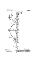
Figure 1 is a top or plan view of a. hinged drag draw bar with the connecting member illustrated in connection therewith; and embodying our invention.
Figure 2 is a detail sectional view on the line 2-2 of Figure 1.
In the accompanying drawings, we have vused the reference numeral 10 to indicate generally the central member' of the draw bar. One or more end members 11 may be hinged to the central draw bar member 10. Each hinge comprises a pair of rear members, comprising a flat bar or the like 12 secured to the rear side'of one of the members 11 and projecting beyond the end thereof, toward the member 10. The projecting end of the bar 12 has an offset portion 13. A coacting bar 14 is fastened to the rear face of the member 10 and projects beyond the end of the member 10 in line with the bar 12 and' to fit just inside of the offset portion 13.
At the lower outer part of the bar 14 is a projecting lug 15, which when the bars 12 and 14 are in alignment with each other stands just below the 'bar 12, as shown in Figure 2, to prevent any downward, tilting y of the bar 12, when the pivot pins are in position. f
Secured to the front face of each member 11 adjacent to its inner end is a hinge bar 16, having an inclined portion 17 extending inwardly and forwardly and terminating in a portion 18 extending away from the `bar 11 in a plane parallel with that of the bar 16. A hinge bar 19 is secured tothe front face of the bar 10 near each end thereof and has a portion 2O inclined forwardly and laterally as shown in Figures 1 and 2 and terminating in aportion 21 inclined away from the bar 10 in a plane parallel with the vplane of the bar portion 19.
The'portion 21 has von its under side a projectinglug 22, so arranged that when the barslG and 19 are inalignment, thelug 22 lies just under the portion 17 in such manner 'as to prevent the downward tilting of the portions 16 and 17 when the hingepins are in place.
The odset portion 15, the outer end of the ,member 14, and the portions 21 and 18 are provided with holes 23, which in the assembled device are in alignment with each other. An eyebolt pivot pin 24 is extended through I the holes 23, as shown in Figure 1, and has the eye of the left-hand eye bolt 24, and
similar jointed, rods 28 are connected with the eye of the right-hand eyebolt 24. These jointed rods 27 and 28 convergeand are connected with a ring 29 at a point substantially in front of the bar 10. Jointed rods 30 connect the band 26 and the ring 29. Y
Between the front and rear hinge membersspacer sleeves 31 are mounted on the eyebolts 24 for holding the front and rear portions of the hinges properly spaced apart.
n practical use, our improved hinged drag draw bar has a number of advantages. It will be understood that harrow sections, not shown, are connected with the bar membersl() and 11 to be drawn behind them. rlhis connection is made by the rings 32 which are connected to the bars 10 and 11 by means of strap-iron bands 33 similar to the band 26. The bands 33 are slidably mounted on the bars and l1 to accommodate hai-row sections of diferent widths and are securely held in any of their adjusted positionsrbytightening the bolts 34.
Ordinarily one section will. be .drawn by each drag bar section 11, and two barrow sections will be drawn by the drag bar seetion 10.
One important advantage of our hinged guide ldraiv bar arises from ytho fact that the pivotally jointed rods 27 and 28 are oonneoted withthe hinge pin eye-bolts 24, and there is'thus no connection between the draft device ring 29 and the drag sect-ions ll, which )night interfere With the swinging Y movement ot' the sections ll.,
The hitch is therefore not interfered Awith in any Way bythe section connections of the drawbar ends.
Another advantage of our structure arises from the use of the bands which may be adjusted to different positions to aoeonnnodate harrow sections of various widths. rfhe peculiar construction of the band 33 prevents distortion when the clamping bolt 34st is tightened. ,The Veo'nstruotion just referred to is the V,shaped loop through which the ring 32 ext-ends which allows the sides of the bandtobe drawn toward each otherand yet prevents bending of the band over the edge of the draw bar due to the pull .of the bolt 34 when tightened.
Sonie changes may be made in the various parts yof our hinged drag drawbar, and it is our intention to Cover by our claim, any modilied `forms of structure or use of niechanical equivalents, which may be reasonablyinelulded Within its scope.
Ve claim as our invention:
A draw bar structurecomprising a boar, connecting ymeans onfsaid bar \,vhereby y.devices may be `connected to the bar-and drawn thereby, said Connecting means x Comprising a band encircling the Vbar andy .engaging three sides thereofythe fourth side of the band being substantially spaced from the fourth side of the bar for providing a substantially V-shaped loop.a clamping bolt extending `throughthefsi-des of lthe band, and engaging the fourth sideof the bar VWhereby said band may be loosened ,and moved longitudinally relativetorthe bar or olaniped thereto, ,the portion of-the band `extending beyond the bolt lServing vto prevent'fdistortionV 0f the band when thebolt is tightened.
Des Moines, IoWaMaroh-9, v1926.
FRANK A... BEssMAN. EMIL WARMBIER.
Priority Applications (1)
| Application Number | Priority Date | Filing Date | Title |
|---|---|---|---|
| US97241A US1663108A (en) | 1926-03-25 | 1926-03-25 | Hinged-drag drawbar |
Applications Claiming Priority (1)
| Application Number | Priority Date | Filing Date | Title |
|---|---|---|---|
| US97241A US1663108A (en) | 1926-03-25 | 1926-03-25 | Hinged-drag drawbar |
Publications (1)
| Publication Number | Publication Date |
|---|---|
| US1663108A true US1663108A (en) | 1928-03-20 |
Family
ID=22262397
Family Applications (1)
| Application Number | Title | Priority Date | Filing Date |
|---|---|---|---|
| US97241A Expired - Lifetime US1663108A (en) | 1926-03-25 | 1926-03-25 | Hinged-drag drawbar |
Country Status (1)
| Country | Link |
|---|---|
| US (1) | US1663108A (en) |
Cited By (1)
| Publication number | Priority date | Publication date | Assignee | Title |
|---|---|---|---|---|
| US2699634A (en) * | 1950-03-11 | 1955-01-18 | Edward B Gortmaker | Harrow hitch |
-
1926
- 1926-03-25 US US97241A patent/US1663108A/en not_active Expired - Lifetime
Cited By (1)
| Publication number | Priority date | Publication date | Assignee | Title |
|---|---|---|---|---|
| US2699634A (en) * | 1950-03-11 | 1955-01-18 | Edward B Gortmaker | Harrow hitch |
Similar Documents
| Publication | Publication Date | Title |
|---|---|---|
| US1663108A (en) | Hinged-drag drawbar | |
| US2562817A (en) | Implement hitch | |
| US2131667A (en) | Draft equalizer | |
| US1715063A (en) | Drawbar for harrows | |
| US1467865A (en) | Drawbar for drags | |
| US2582750A (en) | Multiple harrow draft device | |
| US1653292A (en) | Farm implement | |
| US1590131A (en) | Multiple-section harrow | |
| US2223134A (en) | Draft equalizer | |
| US1478886A (en) | Attachment for harrows | |
| US1051835A (en) | Harrow-folding device. | |
| US1646768A (en) | Draft equalizer | |
| US2327236A (en) | Flexible adjustable lever drag harrow | |
| US1435107A (en) | Draft device for harrows | |
| US1621031A (en) | Drawbar for drags | |
| US2716853A (en) | Harrow drawbar | |
| US1672038A (en) | Draft evener for harrows | |
| US1370834A (en) | Doubletree | |
| US927713A (en) | Lock-jointed foldable draft-beam for sectional harrows. | |
| US1922376A (en) | Corn harvesting machine | |
| US867731A (en) | Harrow. | |
| US1708328A (en) | Folding drag bar for harrows | |
| US1428360A (en) | Harrow | |
| US1440922A (en) | Equalizing harrow hitch | |
| US2055013A (en) | Collapsible drag |