US1663107A - Towel holder - Google Patents
Towel holder Download PDFInfo
- Publication number
- US1663107A US1663107A US170318A US17031827A US1663107A US 1663107 A US1663107 A US 1663107A US 170318 A US170318 A US 170318A US 17031827 A US17031827 A US 17031827A US 1663107 A US1663107 A US 1663107A
- Authority
- US
- United States
- Prior art keywords
- towel
- portions
- members
- holding members
- hinges
- Prior art date
- Legal status (The legal status is an assumption and is not a legal conclusion. Google has not performed a legal analysis and makes no representation as to the accuracy of the status listed.)
- Expired - Lifetime
Links
- 241000396922 Pontia daplidice Species 0.000 description 1
- 239000004744 fabric Substances 0.000 description 1
- 239000000463 material Substances 0.000 description 1
- 239000002184 metal Substances 0.000 description 1
- 239000002023 wood Substances 0.000 description 1
Images
Classifications
-
- A—HUMAN NECESSITIES
- A47—FURNITURE; DOMESTIC ARTICLES OR APPLIANCES; COFFEE MILLS; SPICE MILLS; SUCTION CLEANERS IN GENERAL
- A47K—SANITARY EQUIPMENT NOT OTHERWISE PROVIDED FOR; TOILET ACCESSORIES
- A47K10/00—Body-drying implements; Toilet paper; Holders therefor
- A47K10/12—Grips, hooks, or the like for hanging-up towels
Definitions
- a further ob ect of my invention is to provide a device of the type described which is especially adapted to take the place of towel racks in bath rooms, and which will open to permit the release of the towel and will resume its normal closed position when the towel has been removed.
- a further object is to provide a device of the type described in whch the towel or the like may be instantly inserted and which will be held securely until it is desired to remove it, when it can be readily removed, as stated.
- Figure 2 is a detail view of one of the spring hinges
- Figure 8 is a plan view
- Figure a is a view showing the manner in which the parts are swung to permit the withdrawal of the towel or cloth.
- a base plate 1 which may have openings 2 by means of which it may be secured to a wall or other suitable supporting surface. Hinged at 3 and 3 are the upper portions 4 and 5, respectively, of the towel retaining means. The lower portions 6 and 7 are hinged, respectively, at 8 and 8.
- the portions 4 and 6 are disposed on one side of the center of the device, while the portions 5 and 7 are disposed on the opposite side.
- Each of the portions 4, 5, 6 and 7 consists of a side wall, such as that shown at 4 and 5 in Figures 1 and 3 with end portions extending toward one another.
- the portions 4 and 6 are arranged to con- HOLDER.
- the interior of the holding members have no sharp corners, thus at P and 5 there is a fillet, while at the contiguo-us edges of the portions 4 and 6 the various parts of the device, the operation Y thereof may be readily understood.
- the holding members are spaced apart as shown in Figure 1.
- the towel ordinarily in a folded condition, is dropped in at the open space at the top.
- the spring hinges hold the parts in such position as to retain the towel.
- a portion of the towel may project below the retaining members, but the springs of the hinges are designed to be strong enough to normally hold the members in position against the force exerted by the weight ofthe towel.
- the opening 9 between the opposed flanges serves the purpose of permitting the towel to be more easily inserted as well as to be easily removed.v
- the device may be made in any suitable material, such as wood or metal, and of various sizes to accommodate articles of different nature.
- a towel-holding device comprising a 'base, a pair of towel-holding members hav 10 pair of holding members spaced from. the first pair and movable toward and away from said first-named pair.
- A-towel holder comprislng a base, up-
- spring hinges for permitting said upper towel-holding members to. swing outwardly, lower towel-holding members having their upper edges normally contiguous With the upper toweLholding members, and" spring hinges for said/lower towel-holding members arranged to permit said lower towel-holding members to swing in a direction at an angle to thedirection of movement of the upper towe'l ho'lding members.
Landscapes
- Health & Medical Sciences (AREA)
- Public Health (AREA)
- Supports Or Holders For Household Use (AREA)
Description
March 20, 1928. B. WHITE TOWEL HOLDER Filed Feb. 23, 1927 z i 4: SIT.
- lNVENTQR 5. l VhlTf BY 16 A'I'IORNEYS Patented Mar. 20, 1928.
UNITE BEVERLY WHITE, OF CHICAGO, ILLINOIS, ASSIGNOR OF ONE-HALF TO CHARLES M.
BENDER, OF CHICAGO, ILLINOI3. I
TOWEL Application filed February a pull in any direction, with no danger of tearing or injuring the article.
A further ob ect of my invention is to provide a device of the type described which is especially adapted to take the place of towel racks in bath rooms, and which will open to permit the release of the towel and will resume its normal closed position when the towel has been removed.
A further object is to provide a device of the type described in whch the towel or the like may be instantly inserted and which will be held securely until it is desired to remove it, when it can be readily removed, as stated.
Other objects and advantages will appear in the following specification, and the novel features of the invention will be particularly pointed out in the appended claims.
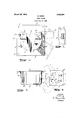
My invention is illustrated in the accompanying drawings, forming part of this application, in which Figure 1 is a face view of the device in its normal position,
Figure 2 is a detail view of one of the spring hinges,
Figure 8 is a plan view, and
Figure a is a view showing the manner in which the parts are swung to permit the withdrawal of the towel or cloth.
In carrying out my invention, I provide a base plate 1 which may have openings 2 by means of which it may be secured to a wall or other suitable supporting surface. Hinged at 3 and 3 are the upper portions 4 and 5, respectively, of the towel retaining means. The lower portions 6 and 7 are hinged, respectively, at 8 and 8.
The portions 4 and 6 are disposed on one side of the center of the device, while the portions 5 and 7 are disposed on the opposite side. Each of the portions 4, 5, 6 and 7 consists of a side wall, such as that shown at 4 and 5 in Figures 1 and 3 with end portions extending toward one another.
The portions 4 and 6 are arranged to con- HOLDER.
23, 1927. v Serial No. 170,318.
tact with one another in the normal position of the device, while the portions 5 and 7 are also arranged to contact." It will be ob served that the outer edges of the portions 4 and 6 as well as of the portions 5 and 7 are arranged in curved form and the hinges are so placed that the upper portions 4 and 5 will swing outwardly as'shown in dotted lines in Figure 1, while the lower portions will swing outwardly and downwardly.
7 It will benoted that the interior of the holding members have no sharp corners, thus at P and 5 there is a fillet, while at the contiguo-us edges of the portions 4 and 6 the various parts of the device, the operation Y thereof may be readily understood. The holding members are spaced apart as shown in Figure 1. In using the'device', the towel, ordinarily in a folded condition, is dropped in at the open space at the top. Normally, the spring hinges hold the parts in such position as to retain the towel. A portion of the towel may project below the retaining members, but the springs of the hinges are designed to be strong enough to normally hold the members in position against the force exerted by the weight ofthe towel.
Now when it. is desired to remove the towel, it may be done by grasping a portion thereof and pulling in any direction. If the pull is straight downwardly, the towel will, spread out to lower members 6 and 7 until it is free. If the pullis to one side, the upper and lower members of that side will be swung on their hinges and when the towel has been removed the spring hinges will return them to their normal position. One may grasp a portion of the towel at the opening between'the opposed flanges and pull straight outwardly. In such case, it may be that all of the members 4, 5, 6 and 7 will be moved slightly on their hinges, but will return when the towel has been removed.
The opening 9 between the opposed flanges serves the purpose of permitting the towel to be more easily inserted as well as to be easily removed.v
The device may be made in any suitable material, such as wood or metal, and of various sizes to accommodate articles of different nature.
I claim:
1. A towel-holding device, comprising a 'base, a pair of towel-holding members hav 10 pair of holding members spaced from. the first pair and movable toward and away from said first-named pair.
2. A-towel holder, comprislng a base, up-
per opposed towel-holding members, spring hinges for permitting said upper towel-holding members to. swing outwardly, lower towel-holding members having their upper edges normally contiguous With the upper toweLholding members, and" spring hinges for said/lower towel-holding members arranged to permit said lower towel-holding members to swing in a direction at an angle to thedirection of movement of the upper towe'l ho'lding members.
BEVERLY WHITE.
Priority Applications (1)
| Application Number | Priority Date | Filing Date | Title |
|---|---|---|---|
| US170318A US1663107A (en) | 1927-02-23 | 1927-02-23 | Towel holder |
Applications Claiming Priority (1)
| Application Number | Priority Date | Filing Date | Title |
|---|---|---|---|
| US170318A US1663107A (en) | 1927-02-23 | 1927-02-23 | Towel holder |
Publications (1)
| Publication Number | Publication Date |
|---|---|
| US1663107A true US1663107A (en) | 1928-03-20 |
Family
ID=22619406
Family Applications (1)
| Application Number | Title | Priority Date | Filing Date |
|---|---|---|---|
| US170318A Expired - Lifetime US1663107A (en) | 1927-02-23 | 1927-02-23 | Towel holder |
Country Status (1)
| Country | Link |
|---|---|
| US (1) | US1663107A (en) |
-
1927
- 1927-02-23 US US170318A patent/US1663107A/en not_active Expired - Lifetime
Similar Documents
| Publication | Publication Date | Title |
|---|---|---|
| US2315566A (en) | Towel rack | |
| US3918589A (en) | Pivoted wicket bag opening dispenser | |
| US1955476A (en) | Flower box holder | |
| US3773288A (en) | Purse hanger | |
| US3522922A (en) | Refuse sack holder and sack | |
| US2229646A (en) | Automatically expanding mail receptacles | |
| US1843391A (en) | Tray supporting device | |
| US2135846A (en) | Garment hanger | |
| US1746962A (en) | Device for suspending and retaining footwear | |
| US1663107A (en) | Towel holder | |
| US4324337A (en) | Article support rack | |
| US1801148A (en) | Cup holder for thermos lunch kits | |
| US1791097A (en) | Laundry-bag holder | |
| US1562417A (en) | Wardrobe suitcase | |
| US1137759A (en) | Folding box. | |
| US2414613A (en) | Mailbox | |
| US930491A (en) | Ironing-cabinet. | |
| US2267113A (en) | Nursing bottle holder | |
| US3226075A (en) | Article holder | |
| US2324093A (en) | Garment hanger | |
| US951628A (en) | Garment-holder. | |
| US1714236A (en) | Safety deposit receptacle | |
| US1559398A (en) | Bathroom fixture | |
| US2470347A (en) | Letter tray | |
| US1450274A (en) | Attachment for ironing boards |