US1663102A - Shipping crate - Google Patents
Shipping crate Download PDFInfo
- Publication number
- US1663102A US1663102A US104761A US10476126A US1663102A US 1663102 A US1663102 A US 1663102A US 104761 A US104761 A US 104761A US 10476126 A US10476126 A US 10476126A US 1663102 A US1663102 A US 1663102A
- Authority
- US
- United States
- Prior art keywords
- crate
- slots
- tongues
- latch
- side members
- Prior art date
- Legal status (The legal status is an assumption and is not a legal conclusion. Google has not performed a legal analysis and makes no representation as to the accuracy of the status listed.)
- Expired - Lifetime
Links
- 210000002105 tongue Anatomy 0.000 description 15
- 238000010276 construction Methods 0.000 description 2
- 238000003197 gene knockdown Methods 0.000 description 2
- 210000005069 ears Anatomy 0.000 description 1
- 230000000717 retained effect Effects 0.000 description 1
- 210000003813 thumb Anatomy 0.000 description 1
Images
Classifications
-
- B—PERFORMING OPERATIONS; TRANSPORTING
- B65—CONVEYING; PACKING; STORING; HANDLING THIN OR FILAMENTARY MATERIAL
- B65D—CONTAINERS FOR STORAGE OR TRANSPORT OF ARTICLES OR MATERIALS, e.g. BAGS, BARRELS, BOTTLES, BOXES, CANS, CARTONS, CRATES, DRUMS, JARS, TANKS, HOPPERS, FORWARDING CONTAINERS; ACCESSORIES, CLOSURES, OR FITTINGS THEREFOR; PACKAGING ELEMENTS; PACKAGES
- B65D88/00—Large containers
- B65D88/52—Large containers collapsible, i.e. with walls hinged together or detachably connected
- B65D88/526—Large containers collapsible, i.e. with walls hinged together or detachably connected with detachable side walls
- B65D88/528—Large containers collapsible, i.e. with walls hinged together or detachably connected with detachable side walls all side walls detached from each other to collapse the container
Definitions
- This invention relates: to an improved metallic shipping crate which is espec ally,
- the invention hasmore specific reference 1 to a crate which" is of knockdown construe
- Fig.2 is a section taken approximately uponthe" plane of the line 22 of Fig. 1 lookingin the direction of the arrows,
- Fig; 3' is a top plan view of the cratey Fig.- 4:"iS'a top plan- VieWbf'the base porti'on ofi the crate structure, I Fig. 5 'is' afside elevation of the crate'in knock-down folded condition,
- Fig- 6 is 'a' fragmentary view showing the manner in which the" angle bar base of'agas stove i (not shown) "is retained in the crate for-"shipping; r i
- FIG. 7 is a I fragmentary" detail section taken onthe'plane of the line 7'7 of Figy2.
- Fig. 8 is a detailperspective'view of one corner portion,exaggerating the latch
- the reference character 1 designates generally the base. This is provided with depending brackets 2 having supporting rollers 3 suitably journaled H1 bearings therein. At'the front of the base is a fork 4 which is swivelly mounted and which isprovided with a caster 5. As is evident from Fig. 4:, this base comprises an elongated rectangular frame which is constructed chiefiy from an angle bar, designated; by the reference character 6.
- Cross i plates-7 extend transversely across the frame and rest'upon" and are secured to the hori-' zontal flange of the surrounding angle bar.- ll-naddi-tiojn, a central cross 1 piece 8 is pro-i vided-.- Thepla-tes- 7 are provided with u'pstandingi-aper'tured' ears 9 inwhichthe;
- a pluralityhoflcatches 12 areprovided. Referring to Figg 6,-it-willbe seen-that each'catch is of the" configuration shown, the same being provided with.
- the catch is; pivotally mounted on a block. 16'whi'ch is'fastened to theunder side of the plate ,7v and this block is providedwith-a fiat spring 17 which, obviously, servesto hold-the? catch in operative position.
- a fiat spring 17 which, obviously, servesto hold-the? catch in operative position.
- The-:top" of the crate is" generally desig nated'by the reference character 18.
- a rectangular framefof angle bar form-19 is provided.
- This frame' is p'rovided withdiagonal cross braces 20 and witha nameplate" or the like 21 (see Figure 8).
- Inadditio'n to the top and bottom frames, there are two pairs of side members, The side members are 'each' designated'by the reference characters 22, and each-side member comprises spaced parallel stripsv23, 2.3. connected together by crossed braces" 24;;
- each latch device comprises a pivotally mounted latch member 33 having a beveled detent 34 to extend through the cooperative slot in the adjacent tongue 25 or 31, as the case may be.
- a retainer 35 is also associated with the latch and in this connection it will be noticed that the latch isprovided with an extension and that the retainer is of right angular form and is pivotally mounted, the retainer being provided with'a keeper notch for reception of the extension on the latch.
- a coiledspring 36 cooperates with the retainer and latch. It is obvious that when the retainer 35 is in the position shown in Fig. 2, the spring 36 presses. the latch in a manner to extend the detent 34 through the aperture in the tongue 31.
- the latches By releasing the retainer, the latches snap into the openings in the various tongues and the structure is assembled in crate form.
- a-wheel supported base a top, side members and end members, said base, to and side members being provided wit latches and cooperating slots, the side members and end. members being provided with apertured tongues extending through said slots, and said latches being engaged With the tongues to retain the parts in assembled relation for producing a crate.
- a bottom and a top each comprising a'rectangular frame of angle bar construction, the vertical flanges'of said frames being provided with slotsand with cooperating internally arranged spring pressedlatches adjacent the slots, and side membersprovided with angularly disposed tongues extending through said slots, the tongues being apertured and said latches being'engaged with the apertures to separably connect the side members with said bottom and top and to maintain said parts in crate forming relation.
- said base and said top comprising rectangular frames of angle bar construction, the vertical flanges of which are provided with horizontally disposed slots, springv pressed latches mounted on said flanges inside of the-frames for cooperation with said slots, a plurality of side members provided at their ends with an larly disposed apertured tongues extendi iig through said slots and engaging with said latches, said side members being provided with'vertic'al slots, additional spring pressed latches carried by the side members'and c'ooperable with said last-named slots, and end. members having laterally directed apertured tongues extending through the vertical slots and' engaged by the last-named latches.
Landscapes
- Engineering & Computer Science (AREA)
- Mechanical Engineering (AREA)
- Rigid Containers With Two Or More Constituent Elements (AREA)
Description
March 20, 1928. 1,663,102
D. TAYLOR SHIPPING CRATE Filed April 26', 19 26 v 2 Sheets-Sheet 1 /9 c 5 v v Inventor 7 Attorney -Marqh 20, 192
D. TAYLOR SHIPPING CRATE Filed April 26. 1926 2 Shuts-Shed! 2- f 7 4 lrw entor Attorney Patented Mar. 20, 1928.
:onitLns TAYLOR, ane ia," onto.
SHIPPING CRATE.
A pplication filed April 26, 1826. Serialflo. 104,761.
This invention relates: to an improved metallic shipping crate which is espec ally,
but notnecessarily, designed for containinga domestic gas stove.
e The invention hasmore specific reference 1 to a crate which" is of knockdown construe,
down'form to be orderly arranged in a compact condition for convenient transportation: a
Other features and advantages ofnthe in- VGHtlOIlWill become apparent from the followingfdescription and drawings.
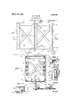
In the accompanying drawings forming a part' of this-application, and. in'which like 25 numerals are employed to'designate like parts throughoutfthe sam e Figureit is aside elevation ofa shipping crate constructed in accordance with" the present invention, showing the same set up for use'.- p
Fig.2 is a section taken approximately uponthe" plane of the line 22 of Fig. 1 lookingin the direction of the arrows,
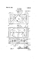
Fig; 3'is a top plan view of the cratey Fig.- 4:"iS'a top plan- VieWbf'the base porti'on ofi the crate structure, I Fig. 5 'is' afside elevation of the crate'in knock-down folded condition,
' Fig- 6 is 'a' fragmentary view showing the manner in which the" angle bar base of'agas stove i (not shown) "is retained in the crate for-"shipping; r i
'Fig. 7 is a I fragmentary" detail section taken onthe'plane of the line 7'7 of Figy2.
Fig. 8 is a detailperspective'view of one corner portion,exaggerating the latch;
Referring to the drawings in detail, it will" be"seen1that. the reference character 1 designates generally the base. This is provided with depending brackets 2 having supporting rollers 3 suitably journaled H1 bearings therein. At'the front of the base is a fork 4 which is swivelly mounted and which isprovided with a caster 5. As is evident from Fig. 4:, this base comprises an elongated rectangular frame which is constructed chiefiy from an angle bar, designated; by the reference character 6. Cross i plates-7 extend transversely across the frame and rest'upon" and are secured to the hori-' zontal flange of the surrounding angle bar.- ll-naddi-tiojn, a central cross 1 piece 8 is pro-i vided-.- Thepla-tes- 7 are provided with u'pstandingi-aper'tured' ears 9 inwhichthe;
hooked lower ends, 10 of retaining bolts 11" a-re fastened. These bolts serve a purpose to be hereinafter described.
It will be noticed that a pluralityhoflcatches 12 areprovided. Referring to Figg 6,-it-willbe seen-that each'catch is of the" configuration shown, the same being provided with. a'nose 18 'to engage a U-shaped clip 14: carried by 'theunder side of the'basebar15 of a'domestic-gas stove (not shown) The catch is; pivotally mounted on a block. 16'whi'ch is'fastened to theunder side of the plate ,7v and this block is providedwith-a fiat spring 17 which, obviously, servesto hold-the? catch in operative position. However, by placing the thumb against the top of-the catch and rocking it downwardly uponits pivot,- itmay 'bereadily di'sengaged-- from the clip 14.
The-:top" of the crate is" generally desig nated'by the reference character 18. Here again,;a rectangular framefof angle bar form-19 is provided. This frame'is p'rovided withdiagonal cross braces 20 and witha nameplate" or the like 21 (see Figure 8). Inadditio'n to the top and bottom frames,,there are two pairs of side members, The side members are 'each' designated'by the reference characters 22, and each-side member comprises spaced parallel stripsv23, 2.3. connected together by crossed braces" 24;;
The, opposite ends of the strips are: bent at I right angles: as indicated at '25 i (see Fig. 2)
:It fo llows that theverticalside flanges of. the top and bottomparts are provided with central elongated slots .26 and relatively short end slots 27 to accommodate these bent ends? or-tongues 25. In addition to the side members 22,. I employ a'pair 'of'duplicate end members 28. i Each end member com? prises horizontal strips 29 connected together by cross pieces 30, alsoarranged in intersecting relation. The ends of the strips 29 are bent at right angles to provide retaining tongues 31. In this connection, it will be noted that the outermost strips 23 'ofthese side members 22 are of right angular crosssection andinclude flanges 32 having slots for passageof the tongues 31. The tongues 31 and in each instance are provided with openings and a multiplicity of latches are provided to cooperate with these apertured tongues, to maintain the respective parts 22 and 28 in assembled relation.
Directing attention to Figs. 2 and 8, it will be seen that each latch device comprises a pivotally mounted latch member 33 having a beveled detent 34 to extend through the cooperative slot in the adjacent tongue 25 or 31, as the case may be. A retainer 35 is also associated with the latch and in this connection it will be noticed that the latch isprovided with an extension and that the retainer is of right angular form and is pivotally mounted, the retainer being provided with'a keeper notch for reception of the extension on the latch. In addition, a coiledspring 36 cooperates with the retainer and latch. It is obvious that when the retainer 35 is in the position shown in Fig. 2, the spring 36 presses. the latch in a manner to extend the detent 34 through the aperture in the tongue 31. In this position the latch is always in readiness to snap into place. However, by seating the extension on the V pivoted end of the latch in the keeper notch in the retainer 35, it is obvious that the detent is maintained in a position to prevent it from engaging the complemental tongue. The latch is thusheld in a disengaged state to facilitate assembling of the parts of the structure. I
By releasing the retainer, the latches snap into the openings in the various tongues and the structure is assembled in crate form. It
1 is obvious that in assembling the structure,
two ofth-e side members 22 are placed on each side, the tongues 25 being extended through the slots 26 and 27. Then the latches are released from the retainers 35 and 1 they automatically snap into place to maintain the parts 22 in assembled relation. In so doing,'the top 18 is connected with the bottom 1. Then the end members 28 are placed in an obvious manner and the crate is fully assembled. The crate may be thus built around the gas stove after the latter has been clamped in place upon the base 1 by means of the aforesaid catches 12. The crate may be readily moved from place to place on the rollers to facilitate handling.
It is; believed that'by considering the description in connection with the'drawings, persons familiar with devices of this class will be able to obtain a clear understanding of the same. Therefore a more lengthy description is thought unnecessar While the preferred embodiment of th invention has been shown and described in detailfit is tobe understood that, minor changes coming within the field of the invention claimed may be resorted to if desired.
Having thus described my invention, what I claim as new is 1. In a crate structure of the class described, a-wheel supported base, a top, side members and end members, said base, to and side members being provided wit latches and cooperating slots, the side members and end. members being provided with apertured tongues extending through said slots, and said latches being engaged With the tongues to retain the parts in assembled relation for producing a crate. 2. In a crate structure of the class described, "a bottom and a top, each comprising a'rectangular frame of angle bar construction, the vertical flanges'of said frames being provided with slotsand with cooperating internally arranged spring pressedlatches adjacent the slots, and side membersprovided with angularly disposed tongues extending through said slots, the tongues being apertured and said latches being'engaged with the apertures to separably connect the side members with said bottom and top and to maintain said parts in crate forming relation.
3. In a crate :of the class described, a'
wheel supported base, meanson said base for separably fastening a stove thereto, a top,
said base and said top comprising rectangular frames of angle bar construction, the vertical flanges of which are provided with horizontally disposed slots, springv pressed latches mounted on said flanges inside of the-frames for cooperation with said slots, a plurality of side members provided at their ends with an larly disposed apertured tongues extendi iig through said slots and engaging with said latches, said side members being provided with'vertic'al slots, additional spring pressed latches carried by the side members'and c'ooperable with said last-named slots, and end. members having laterally directed apertured tongues extending through the vertical slots and' engaged by the last-named latches.
' In testimony whereof I aflix my signature. 7
DALLAS TAYLOR;
Priority Applications (1)
| Application Number | Priority Date | Filing Date | Title |
|---|---|---|---|
| US104761A US1663102A (en) | 1926-04-26 | 1926-04-26 | Shipping crate |
Applications Claiming Priority (1)
| Application Number | Priority Date | Filing Date | Title |
|---|---|---|---|
| US104761A US1663102A (en) | 1926-04-26 | 1926-04-26 | Shipping crate |
Publications (1)
| Publication Number | Publication Date |
|---|---|
| US1663102A true US1663102A (en) | 1928-03-20 |
Family
ID=22302228
Family Applications (1)
| Application Number | Title | Priority Date | Filing Date |
|---|---|---|---|
| US104761A Expired - Lifetime US1663102A (en) | 1926-04-26 | 1926-04-26 | Shipping crate |
Country Status (1)
| Country | Link |
|---|---|
| US (1) | US1663102A (en) |
Cited By (3)
| Publication number | Priority date | Publication date | Assignee | Title |
|---|---|---|---|---|
| US5711451A (en) * | 1995-08-04 | 1998-01-27 | Gavin; Norman W. | Concrete tank support system |
| US20040002869A1 (en) * | 2002-06-28 | 2004-01-01 | Ekstein Erik T. | Method and system for storing items using a portable closet |
| US10618689B1 (en) | 2018-09-28 | 2020-04-14 | International Business Machines Corporation | Top cap guard |
-
1926
- 1926-04-26 US US104761A patent/US1663102A/en not_active Expired - Lifetime
Cited By (3)
| Publication number | Priority date | Publication date | Assignee | Title |
|---|---|---|---|---|
| US5711451A (en) * | 1995-08-04 | 1998-01-27 | Gavin; Norman W. | Concrete tank support system |
| US20040002869A1 (en) * | 2002-06-28 | 2004-01-01 | Ekstein Erik T. | Method and system for storing items using a portable closet |
| US10618689B1 (en) | 2018-09-28 | 2020-04-14 | International Business Machines Corporation | Top cap guard |
Similar Documents
| Publication | Publication Date | Title |
|---|---|---|
| US1549146A (en) | Collapsible table | |
| US3078957A (en) | Collapsible sawhorse bracket assembly | |
| US1663102A (en) | Shipping crate | |
| US2738245A (en) | Knock-down metal furniture, including cross u-shaped legs | |
| US1372180A (en) | Display-shelving | |
| US584811A (en) | Rack for dry goods | |
| US1766316A (en) | Bleacher structure | |
| US327413A (en) | Knockdown table | |
| US1785143A (en) | Knockdown stove | |
| US2724511A (en) | Display racks or stands | |
| US2078587A (en) | Foldable support for ironing tables | |
| US561703A (en) | Folding booth | |
| US2683483A (en) | Demountable chair | |
| US263945A (en) | Clothes-frame | |
| US1744646A (en) | Drawer-locking device | |
| US1312891A (en) | Planoiitlal m | |
| US1563799A (en) | Adjustable knockdown bookstand and shelving | |
| US1435346A (en) | Folding camp stove | |
| US1560913A (en) | Leg-locking device | |
| US585722A (en) | Folding bicycle-rack | |
| US1689481A (en) | Shelving | |
| US1801993A (en) | Supporting structure | |
| US744315A (en) | Plate-rack. | |
| US595476A (en) | Charles heller | |
| USRE14995E (en) | doesk |