US1663019A - Automatic die-press-stopping mechanism - Google Patents
Automatic die-press-stopping mechanism Download PDFInfo
- Publication number
- US1663019A US1663019A US167411A US16741127A US1663019A US 1663019 A US1663019 A US 1663019A US 167411 A US167411 A US 167411A US 16741127 A US16741127 A US 16741127A US 1663019 A US1663019 A US 1663019A
- Authority
- US
- United States
- Prior art keywords
- press
- vacuum
- hand lever
- lever
- stopping mechanism
- Prior art date
- Legal status (The legal status is an assumption and is not a legal conclusion. Google has not performed a legal analysis and makes no representation as to the accuracy of the status listed.)
- Expired - Lifetime
Links
- 230000002159 abnormal effect Effects 0.000 description 18
- 239000000463 material Substances 0.000 description 7
- 238000010276 construction Methods 0.000 description 2
- ATJFFYVFTNAWJD-UHFFFAOYSA-N Tin Chemical compound [Sn] ATJFFYVFTNAWJD-UHFFFAOYSA-N 0.000 description 1
- 238000013459 approach Methods 0.000 description 1
- 230000006835 compression Effects 0.000 description 1
- 238000007906 compression Methods 0.000 description 1
- 230000000881 depressing effect Effects 0.000 description 1
- 239000012634 fragment Substances 0.000 description 1
- 230000005484 gravity Effects 0.000 description 1
- 229920000136 polysorbate Polymers 0.000 description 1
Images
Classifications
-
- B—PERFORMING OPERATIONS; TRANSPORTING
- B21—MECHANICAL METAL-WORKING WITHOUT ESSENTIALLY REMOVING MATERIAL; PUNCHING METAL
- B21D—WORKING OR PROCESSING OF SHEET METAL OR METAL TUBES, RODS OR PROFILES WITHOUT ESSENTIALLY REMOVING MATERIAL; PUNCHING METAL
- B21D55/00—Safety devices protecting the machine or the operator, specially adapted for apparatus or machines dealt with in this subclass
Definitions
- This invention relates to automatic die press stopping mechanism and itsprincipal object is to provide pneumatic, emergency press stopping mechanism, automatic in operation, and arranged to stop the press in case more than one thickness of material lodges between the dies.
- the invention has reference more particularly to automatic power presses or die presses in which strips of tin or other lightgauge material are automatically fed, one at a time, to the dies. 00- casionally the pieces, which are blanked out by the dies, fail to discharge from the dies,
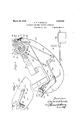
- Fig. 1 is a side elevation, (withthe crank shaft thereof shown in cross section) of an automatic die press, stripped of much of its operating mechanism and showing a'simple OllllJOtjlilllGIlt of the present invention applied thereto;
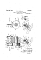
- F 2 is a detail view, partly in front elevation and partly in cross section, of the vacuum release mechanism, which operates to release the vacuum'in the vacuum head when an abnormal condition arises'between the dies
- Fig. 3 is a detail vertical cross section taken on the line 33 of Fig. 2;
- Fig. at is a detail view partly in side elevas tion and partly in central vertical section, of a fragment of thelhand lever and vacuum head;
- Fig. 5 is a view similar toFig.
- Fig. 4 but' showing the handle released from the vacuum head; Fig. dis a detail, fragmental view, partly in section of the vacuum release valve and associated parts, and Fig. 7 is a sideelevation of a slightly modified form of the invent-ion. 7.
- Such clutch and brake mechanism usually comprises. a clutch shoe 15, whichis arranged-to engage and retract a clutch pin 16, which connects the continuously rotating element withan element fast on the crank shaft, and the brake mechanism usually comprises a brake band 17, which is arrangedto engage with a brake drum 18 and having a spreader 19 for spreading the ends of the brake band part to l brake band on the brake drum.
- the clutch shoe 15 and spreader 19 are connected to an operating strut 21 by links 22, 23 and the operating strut 21 is connected to the hand lever 24 by alink 25.
- the vacuum-head con- ,tains a bore or cavity 30, which leads from an air inlet opening 31 in the mouth of the suction cup or pad 28, and at its upper end said bore 30 is enlarged in diameter as at 30*, and formed with a valve seat 32 on which may seat a valve 33 which is mounted on the upper end of a valve stem 34, which extends through the bore 30 and engages with the hand lever, whenever the latter is raised into engagement with the suction cup or pad 28.
- a coiled compression spring 35 interposed between the valve 33, and a plug 36 in the top of the vacuum head,operates to facilitate the seating of the valve whenever the hand lever is moved away from the valve stem 34.
- vent pipe 40 leads to a po 7 sit-ion adjacent the crank shaft 13 and its extreme end contains an inlet opening arranged to be closed under normal conditions by a vacuum release valve 41.
- Figs. 2 and 3 the usual cheek 42 of the crank shaft 13 will be seen, and on said cheek are secured cam blocks 43, 43, which are arranged to run idle or inactive so long as the conditions between the dies remain normal. WVhen, however, two or more thicknesses of material lodge be tween the dies an abnormal strain is placed against the crank shaft and the check 42 thereof is thereby moved bodilya trifle,and when thus moved the cheek 42 engages the vacuum release valve mechanism and therebyopens the vacuum release valve 41 for the vent pipe 40, consequently admitting air through said vent pipe 40 to the'bore 30 of the vacuum head 27 and releasing the vacuum therein, permitting the hand lever 24 to fall, and'as a consequence, disengaging the clutch and applying the brake mechanism, and thereby stopping the press.
- the valve stem 34 As the disc like part 29 of the hand lever 24 approaches the vacuum head it engages the valve stem 34, unseats the valve 33 thereby permitting the vacuum in the vacuum pipe 37 to extend through the bore 80 to the mouth of the suction cup or suction pad'28, and the hand lever is thereby held against the suction cup in its operative position.
- The'strips being fed to the dies in the usual manner, the dies operate on the strips and so long as a normal condition remains between the dies, the press stopping mechanism remains inactive.
- the cam block 43 is placed on the side of the cheek 42 opposite the crank pin 14, so that said cam block engages the lever actuating pin 45 at the time that the ram is at the bottom of its working stroke.
- the instant the air vent to the vent tube 40 is opened,.air is admitted therethrough and through the bore '30 to the mouth of the suction or pad 28, whereupon the vacuum is released, permitting the hand lever tofall (see Fig. 5) and thereby disengage the clutch and a. ply the brake through the instrumentality of the link 25, operating strut .21, and links 22, 23.
- the clutch pin 16 engages the clutch shoe 15 the fly wheel becomes disconnected. from the crank shaft and the rotation of the crank shaft is arrested by the application of the brake band to the brake drum.
- the spring seats the valve 33 and closes the passage from the vacuum pipe 37 to the bore 80.
- the cam block 43 passes the pin 46, raises it and therewith the lever 48, bringing the valve plate 41 into contact with the open end of the vent tube and closing the vent to the vacuum head whereby when the hand lever is again raised, into contact with the suction end of the vacuum head, it will be held in raised position.
- the hand lever is forcibly swung down thereby releasing the vacuum in the conduit 30.
- the valve 35 is thereby permitted to seat, thus closing the entrance to the vacuum pipe 37 and avoiding any leak at this point.
- Fig. 7 a slightly modified form of the invent-ion is illustrated.
- the vacuum head 27 is applied to an arm 24 of the lever.
- T hearm 24 may be placed on the lside of thepress body 10 opposite the one on which the handle portion 24 is placed.
- the twov arms 24 24 of the hand over are rigidly connected by'a cross connectionin the form of a shaft26 securedin the lever arms 24, 24 and extending through the press body and rotatively mounted therein.
- V I j It will be understood that wherever the expression hand lever occurs in the claims it is ntended to include a hand level of the first or second order and one in which the vacuum head may be applied to any arm thereof.
- automatic press stopping mechanism having manually operated starting and stopping mechanism
- the combination with the hand lever of the press starting and stopping mechanism of a vacuum head having a suction end arranged to contact with said hand lever when in operative position, said vacuum head being connected with a vacuum source, and having a norn'ially closed air vent, and vacuum release means for said air vent, capable of being operated by the press mechanism when subjected to an abnormal condition in the press, whereby the vacuum at the suction end of the vacuum head is released and the hand lever thereby released therefrom.
- a ventcover arranged to open and closesaid air vent, spaced cam blocks mounted on, said crank shaft for opening and closing said air vent when the crank shaft is subjected to abnormal strain, and lever actuating struts arranged to be actuated by said cam blocks under an abnormal condition of said crank shaft, whereby the vacuum is relezsedin said vacuum head, and the hand lever is thereby released from its operative position.
- the hand lever of press starting and stopping mechanism In pneumatic means for holding in operative position, the hand lever of press starting and stopping mechanism.
- a vacuum head having a suction end adapted to contact with the hand lever, said suction head having a chamber connected to a vacuum supply, and a conduit leading from said chamber to its suction end, avalve arranged to seat upon a valve seat between said chamber and conduit, and having a valve stem adapted to be engaged by the hand lever and the valve thereby unhead, a vent tube leading from said conduit and means for opening and closing the vent in said vent tube, to release the vacuum in said conduit and thereby release the hand lever therefrom.
- a vacuum head having a suction end adapted to contact with the hand lever, said suction head having a chamber connected to a vacuum supply, and a conduit leading from said chamber to its suction end, a valve arranged to seat upon a valve seat between said chamber and conduit, and having a valve stem adapted to be engaged by the hand lever and the valve thereby unseated when the hand lever is brought into contact with the suction end of the vacuum head, a vent tube leading from said conduit, a die press crank shaft, vent opening and closing means for said vent tube, and normally inactive means carried by said crank shaft arranged to engage and operate said vent opening and closlng means, when the crank shaft is subjected to an abnormal strain.
- a vacuum head having a suction end adapted to contact with the hand lever, said suction head having a chamber connected to a vacuum supply, and a conduit leading from said chamber to its suction end, a.
- valve arranged to set upon a valve seat bet-ween said chamber and conduit, and having a valve stem adapted to be engaged by the hand lever, and the valve thereby unseated when the hand lever is brought into contact with the suction end of the vacuum head, a vent tube leading from said conduit, a die press crank shaft, spaced cam blocks thereon, a throw amplifying lever, having means for closing the vent in said vent tube, and operating struts interposed between said cam blocks and lever, one on each side of its fulcrum and arranged to be engaged by said cam blocks when the crank shaft is subjected to an abnormal strain.
- automatic press stopping mechanism for die presses having manually operated press starting and stopping mechanism
- a vacuum head body having an air conduit therein.
Landscapes
- Engineering & Computer Science (AREA)
- Mechanical Engineering (AREA)
- Press Drives And Press Lines (AREA)
Description
March 20, 19 28. C. D. MCDONALD AUTOMATIC DIE PRESS STOPPING MECHANISM Filed Feb.ll, 1927 2 Sheets-Sheet 1 March 20, 1928.
' 1,663,019 c. D. MCDONALD AUTOMATIC DIE PRESS STOPPING MECHANISM Filed Feb.1l', 1927 2 Sheets-Sheet 2 Patented Mar. 20, 1928.
CHARLES D. .MCDONALD, OF CHICAGO, ILLINOIS, ASSIG-NOR T0 MCDONALD MACHINE 00., OF GHICAGQ ILLINOIS, A CORPORATION OF ILLINOIS.
AUTOMATIC DIE-PRESS-STOIPING MECHANISM.
Application filed February 11, 1927.
This invention relates to automatic die press stopping mechanism and itsprincipal object is to provide pneumatic, emergency press stopping mechanism, automatic in operation, and arranged to stop the press in case more than one thickness of material lodges between the dies. The invention has reference more particularly to automatic power presses or die presses in which strips of tin or other lightgauge material are automatically fed, one at a time, to the dies. 00- casionally the pieces, which are blanked out by the dies, fail to discharge from the dies,
with the result that on the next stroke of the dies more than one thickness of material lodges between them and as a consequence some part of the press has to give to accominc-date theabnormal condition which occurs, and in. such event the-crank shaft is apt to be sprung or'other ,parts'of the pressare apt to bedamaged. In accordance with the pres-' ent invention the press is automatically stopped in case two or more thicknesses of material lod e between the dies. Another object is to provide pneumatic means for holding the press starting and stopping lever in operative position and for releasing it from such posit-ion when an abnormal condition arises between the dies.
With these objects and advantages'in view, this invention consists in automatic press stopping mechanism embodying a vacuum: head having a'suction cup or pad arranged to be engaged by the usual hand lever which operates the clutch and brake mechanism of the press, and means operated by the crank shaft under abnormal conditions for releasing the vacuum in said vacuum head and permitting said hand lever to automatically throw the clutch and apply the-brake, thereby stopping the press. It further consists in automatic press stopping mechanism, in which the hand lever is normally held'in starting position by a vacuum head, in which the vacuum is released whenever'an abnormal condition arises between the dies, thereby permitting the hand lever to move and actuate the clutch and brakemechanism to stop the press. The invention further con i i in the several novel features of contion, arrangement and combination of ts herei ifter fullyset forth and claimed. The invention is clearly illustrated in the Serial No. 167,411.
drawing accompanying this specification, in which: r
Fig. 1 is a side elevation, (withthe crank shaft thereof shown in cross section) of an automatic die press, stripped of much of its operating mechanism and showing a'simple OllllJOtjlilllGIlt of the present invention applied thereto; F 2 is a detail view, partly in front elevation and partly in cross section, of the vacuum release mechanism, which operates to release the vacuum'in the vacuum head when an abnormal condition arises'between the dies Fig. 3 is a detail vertical cross section taken on the line 33 of Fig. 2; Fig. at is a detail view partly in side elevas tion and partly in central vertical section, of a fragment of thelhand lever and vacuum head; Fig. 5 is a view similar toFig. 4: but' showing the handle released from the vacuum head; Fig. dis a detail, fragmental view, partly in section of the vacuum release valve and associated parts, and Fig. 7 is a sideelevation of a slightly modified form of the invent-ion. 7.
Referring to said drawing, which illustrates a simple embodiment of the invention, the reference character 101 designates the body or frame of an automatic die press of conventional form having the usual bolster 11,for receiving the lower or stationary die, the ram 12 for holding the upper or movable die and thecrank shaft 13 connected to said ram by acrank 14 as usual. Automatic die presses are usually provided with clutch and brake mechanism whereby the power pulley or. other driving element may rotate continuously and the crank shaft may be clutched thereto or unclutched therefrom as desired. Die presses equipped v with such clutch and brake mechanism are more fully shown and described in my prior Letters. Patent,'No. 1,252,278, dateddanuary'l,1918,
and No. 1,529,031, dated March 10, 1925, to
which reference ismade. Such clutch and brake mechanism usually comprises. a clutch shoe 15, whichis arranged-to engage and retract a clutch pin 16, which connects the continuously rotating element withan element fast on the crank shaft, and the brake mechanism usually comprises a brake band 17, which is arrangedto engage with a brake drum 18 and having a spreader 19 for spreading the ends of the brake band part to l brake band on the brake drum. The clutch shoe 15 and spreader 19 are connected to an operating strut 21 by links 22, 23 and the operating strut 21 is connected to the hand lever 24 by alink 25. The operating strut and hand lever are fulcrumed upon the press body 10 and the parts are so proportioned and arranged that when the hand lever is in operative position (as shown) with the press running, the link 25 has not passed the dead center line between its ends and the fulcrum 26 of the hand lever. hen in operative position, with the press running the handle occupies a position from which it may freely move by gravity when released, in which case the clutch is disconnected and the brake applied. Figs. 1 and 4 of the drawings show thehand lever in the position occupied when the press 18 running.
A vacuum head 27, secured to the press body,is provided for holding the hand lever in operative position. Said vacuum head 27 is provided at one end with a suction cup or suction pad 28 and the hand lever is formed with a flat disc like part 29 arranged to engage with said suction cup or suction pad whenever the hand lever is raised to its effective position. The vacuum-head con- ,tains a bore or cavity 30, which leads from an air inlet opening 31 in the mouth of the suction cup or pad 28, and at its upper end said bore 30 is enlarged in diameter as at 30*, and formed with a valve seat 32 on which may seat a valve 33 which is mounted on the upper end of a valve stem 34, which extends through the bore 30 and engages with the hand lever, whenever the latter is raised into engagement with the suction cup or pad 28. A coiled compression spring 35, interposed between the valve 33, and a plug 36 in the top of the vacuum head,operates to facilitate the seating of the valve whenever the hand lever is moved away from the valve stem 34. Leading into the enlarged portion 30 of the bore or cavity, is the end of a vacuum pipe 37, which connects with a suitable source for maintaining a partial vacuum in the bore or cavity of the vacuum head, and as well as in the other vacuum devices of the press. As is usual a vacuum pump (not shown) is employed for creating the partial vacuum forthe strip liftersand certain other devices of an automatic power press and if desired a vacuum tank 38 may be employed, which is connected to the vacuum pump (not shown) and from which leads a main vacuum line39 to which is connected the vacuum pipe 37, which leads to the vacuum head 27. It will be observed that when the hand lever 24 is in contact with the suction cup or pad of restricted part of theair conduit 30 immediately below the valve seat, in order that when air is admitted through the vent tube 40, the vacuum in the suction head may be overcome. The vent pipe 40 leads to a po 7 sit-ion adjacent the crank shaft 13 and its extreme end contains an inlet opening arranged to be closed under normal conditions by a vacuum release valve 41.
Referring now to Figs. 2 and 3, the usual cheek 42 of the crank shaft 13 will be seen, and on said cheek are secured cam blocks 43, 43, which are arranged to run idle or inactive so long as the conditions between the dies remain normal. WVhen, however, two or more thicknesses of material lodge be tween the dies an abnormal strain is placed against the crank shaft and the check 42 thereof is thereby moved bodilya trifle,and when thus moved the cheek 42 engages the vacuum release valve mechanism and therebyopens the vacuum release valve 41 for the vent pipe 40, consequently admitting air through said vent pipe 40 to the'bore 30 of the vacuum head 27 and releasing the vacuum therein, permitting the hand lever 24 to fall, and'as a consequence, disengaging the clutch and applying the brake mechanism, and thereby stopping the press. As shown the operative connections between the cam block 43 and vacuum release valve 41 comprise a bracket 44 bolted or otherwise secured to the press body 10 and having pins 45, 46 slidably guided therein and adapted under abnormal conditions to be engaged by the cam blocks 43, 43 The pins 45, 46 are formed with heads 47 upon their upper ends which normally rest upon the upper face of the bracket, and'the upper ends of said pins are arranged toengage with a lever 48, fulcrumed between said pins on an arm 49 which extends up from the bracket 44. In-
lever 48. The adjustment screws are adjusted so that the cam blocks 43, 43 may pass by the pins 45, 46 without affecting them under normal working conditions of g the dies, but when two or more thicknesses of material lodge between the dies the ram and iii) crank shaftare subjected to an abnormal strain at the time the crank passes the dead center during its working stroke, the result v being that the cam block 43 is brought into eifective contact with the pin 45 and the lever 48 is thereupon swung down and the release valve 41 opened thereby admitting air to the vent tube 40 and through it to the bore of the vacuum head, whereby the vacuum therein is released, and the hand lever 24 being thereby freed, it swings down and disconnects the clutch and applies the brake through the link 25, operating strut 21 and links 22, 23.
In the operation of the automatic press stopping mechanism forming the subject matter of the specification, a partial vacuum is constantly created in the vacuum head *27 and if the press is equipped with a vacuum pump the low pressure may be supplied by said vacuum pump, otherwise a separate vacuum pump and avacuum tank 38 may be provided for supplying the press with low pressure. To start the press, the lever 24 is raised from an inactive position :to its active position as seen in Figs. 1 and 4 andthe clutch shoe 15 is thereby retracted and the brake bands loosened from the brake drum, permitting the drive wheel to operate "the press mechanism as usual. As the disc like part 29 of the hand lever 24 approaches the vacuum head it engages the valve stem 34, unseats the valve 33 thereby permitting the vacuum in the vacuum pipe 37 to extend through the bore 80 to the mouth of the suction cup or suction pad'28, and the hand lever is thereby held against the suction cup in its operative position. The'strips being fed to the dies in the usual manner, the dies operate on the strips and so long as a normal condition remains between the dies, the press stopping mechanism remains inactive. If, however, two or more thicknesses of material lodge between the dies I an abnormal strain is thereby produced on the ram and crank shaft when the upper die is brought down upon the work, and the crank shaft is thereby bodily moved a' trifle thereby bringing the cam block 43 into effective contact with the pin 45, and lifting the short arm of the lever 48 and depressing the long arm which carries the vacuum release valve 41. It will be noticed that the long arm of the lever 48 is several times the length of the short arm thereby providing a stroke amplifying lever, which gives sufficient movement to the vacuum release valve to afford free entrance of air to the vent tube 40. The cam block 43 is placed on the side of the cheek 42 opposite the crank pin 14, so that said cam block engages the lever actuating pin 45 at the time that the ram is at the bottom of its working stroke. The instant the air vent to the vent tube 40 is opened,.air is admitted therethrough and through the bore '30 to the mouth of the suction or pad 28, whereupon the vacuum is released, permitting the hand lever tofall (see Fig. 5) and thereby disengage the clutch and a. ply the brake through the instrumentality of the link 25, operating strut .21, and links 22, 23. As soon as the clutch pin 16 engages the clutch shoe 15 the fly wheel becomes disconnected. from the crank shaft and the rotation of the crank shaft is arrested by the application of the brake band to the brake drum. As the hand lever 24 moves away from the suction head 27, the spring seats the valve 33 and closes the passage from the vacuum pipe 37 to the bore 80. Before the press stops, the cam block 43 passes the pin 46, raises it and therewith the lever 48, bringing the valve plate 41 into contact with the open end of the vent tube and closing the vent to the vacuum head whereby when the hand lever is again raised, into contact with the suction end of the vacuum head, it will be held in raised position. To manually stop the press, the hand lever is forcibly swung down thereby releasing the vacuum in the conduit 30. The valve 35 is thereby permitted to seat, thus closing the entrance to the vacuum pipe 37 and avoiding any leak at this point.
In Fig. 7 a slightly modified form of the invent-ion is illustrated. In place of applying the vacuum head 27 directly to the, arm of the hand ilever, which contains the handle, the vacuum head 27 is applied to an arm 24 of the lever. T hearm 24 may be placed on the lside of thepress body 10 opposite the one on which the handle portion 24 is placed. The twov arms 24 24 of the hand over are rigidly connected by'a cross connectionin the form of a shaft26 securedin the lever arms 24, 24 and extending through the press body and rotatively mounted therein. V I j It will be understood that wherever the expression hand lever occurs in the claims it is ntended to include a hand level of the first or second order and one in which the vacuum head may be applied to any arm thereof.
While the invention has been shown and described in connection with a vacuum head, it is obvious that other means may be employed for supporting the hand lever in raised or start ng position and that pneumatic means, either in form of pressure or vacuum may be employed for releasing the handlever from such position.
More or less variation of the exact details construction is possible without departing from the spirit of this invention; I desire. therefore, not to limit myself to the or;- act form of the construction shown and de-v scribed, but intend, 1n the following claims,
to point out all of the invention disclosed herein.
ill)
ill!!! I claim as new, and desire to secure by' Letters Patent:
1. In automatic press stopping mechanism, having manually operated starting and stopping mechanism, the combination with the hand lever of the press starting and stopping mechanism, of a vacuum head having a suction end arranged to contact with said hand lever when in operative position, said vacuum head being connected with a vacuum source, and having a norn'ially closed air vent, and vacuum release means for said air vent, capable of being operated by the press mechanism when subjected to an abnormal condition in the press, whereby the vacuum at the suction end of the vacuum head is released and the hand lever thereby released therefrom.
2. In automatic press stopping mechanism for die presses having die moving mechanism, the combination with the hand lever of the press starting and stopping mechanism, of a vacuum head having a suction end arranged to contact with said hand lever when in operative position, said vacuum head being connected with a vacuum source, and having a normally cloijed air vent controlled, by a vacuum releasevalve, and normally inactive valve actuating means operated by the die moving mechanism of the press when subjected to an abnormal condition between the dies.
3. In automatic press stopping mechanism for die presses having starting and stopping mechanism and a crank shaft for operating theram of the press, the combination with the hand lever'of the press starting and stopping mechanism, of a vacuum head having a suction end arranged to contact with inactive cam block mounted on the crank shaft of the press and arranged to operate said valve actuating. means when the ram and crank shaft are subjected to abnormal strain, and thereby relieve the vacuum in the vacuum head, whereby the hand lever is released therefrom.
4:- In automatic press stopping mechanism for die presses having manually operated press starting and stopping mechanism, and a crank shaftfor operating the ram of the press, the combination with the hand lever of the press starting and stopping mechanism, of a vacuum head having a suction end arranged to contact with said hand lever when in operative, position, said vacuum head being connected with a vacuum source and having a vent tube opening to its suction end and leading therefrom, there being an air vent in said tube controlled by a vacuum release valve normally closing said air vent, a throw amplifying lever for actuating said valve, and normally inactive lever actuating means mounted on the. crank shaft of the press arranged to actuate said lever when the crank shaft is subjected to abnormal strain.
5. In automatic press stopping mechanism for die presses having manually operated press starting and stopping mechanism, and a crank shaft for operatingthe ram of the press, the combination with the hand lever of the press starting and stopping mechanism, of a vacuum head having a suction end arranged to contact with said'hand lever when in operative po:ition, said vacuum head being connected with a vacuum source, and having a vent tub-e opening to its suction end and leading therefrom, there being a normally closed air vent in said vent tube, a throw amplifying lever having. a ventcover, arranged to open and closesaid air vent, spaced cam blocks mounted on, said crank shaft for opening and closing said air vent when the crank shaft is subjected to abnormal strain, and lever actuating struts arranged to be actuated by said cam blocks under an abnormal condition of said crank shaft, whereby the vacuum is relezsedin said vacuum head, and the hand lever is thereby released from its operative position.
6. In automatic press stopping mechanism for diepresses having manually operated press starting and stopping mechanism, and a crank shaft for operating the ram of the press, the combination with the hand lever of the press starting and stopping mechanism, of a vacuum head having a suction end arranged to contact with said hand lever when in operative position, said vacuum head being connected to a vacuum source and having a vent tube opening to its suction end, and leading therefrom, there being a normally closed air vent in said vent tube,-vent closing means, and operative connections between said vent closing means and the crank shaft of the press for opening and closing said vent when said crank shaft is subjected to an abnormal strain, whereby the vacuum in the suction end of the vacuum head is released andt-he hand lever released therefrom. p ,7. In pneumatic means for holding in operative position, the hand lever of press starting and stopping mechanism. the combination of'a vacuum head, having a suction end adapted to contact with the hand lever, said suction head having a chamber connected to a vacuum supply, and a conduit leading from said chamber to its suction end, avalve arranged to seat upon a valve seat between said chamber and conduit, and having a valve stem adapted to be engaged by the hand lever and the valve thereby unhead, a vent tube leading from said conduit and means for opening and closing the vent in said vent tube, to release the vacuum in said conduit and thereby release the hand lever therefrom.
8. In pneumatic means for holding in operative position, the hand lever of press starting and stopping mechanism, the combination of a vacuum head, having a suction end adapted to contact with the hand lever, said suction head having a chamber connected to a vacuum supply, and a conduit leading from said chamber to its suction end, a valve arranged to seat upon a valve seat between said chamber and conduit, and having a valve stem adapted to be engaged by the hand lever and the valve thereby unseated when the hand lever is brought into contact with the suction end of the vacuum head, a vent tube leading from said conduit, a die press crank shaft, vent opening and closing means for said vent tube, and normally inactive means carried by said crank shaft arranged to engage and operate said vent opening and closlng means, when the crank shaft is subjected to an abnormal strain.
9. In pneumatic means for holding in operative position and releasing the hand lever of press starting and stopping mechanism, the combination of a vacuum head having a suction end adapted to contact with the hand lever, said suction head having a chamber connected to a vacuum supply, and a conduit leading from said chamber to its suction end, a. valve arranged to set upon a valve seat bet-ween said chamber and conduit, and having a valve stem adapted to be engaged by the hand lever, and the valve thereby unseated when the hand lever is brought into contact with the suction end of the vacuum head, a vent tube leading from said conduit, a die press crank shaft, spaced cam blocks thereon, a throw amplifying lever, having means for closing the vent in said vent tube, and operating struts interposed between said cam blocks and lever, one on each side of its fulcrum and arranged to be engaged by said cam blocks when the crank shaft is subjected to an abnormal strain.
10. In automatic press stopping mechanism for die presses, the combination of a vacuum head having a suction end adapted for engagingwith the press starting and stopping lever and a vent tube leading from said suction end of the vacuum head, spaced cam blocks mounted on the crank shaft of the die press, a lever having means for opening and closing the vent in the vent tube, operating struts interposed between the cam blocks and lever, and arrangedrto be engaged by said cam blocks when the crank shaft is subjected to an abnormal strain and adjustment screws between said lever and operating struts. V
11. In automatic press stopping mechanism for die presses having manually operated press starting and stopping mechanism, the combination with the hand lever of the press starting and stopping mechanism, of a pneumatically operated member engaging said hand lever and holding it in 0 perative position, and automatic release means operated by the press mechanism and having an air conduit leading to said pneumatically operated member for the hand lever.
12. In a vacuum head for. holding in operative position the hand lever of press starting and stopping mechanism, a vacuum head body having an air conduit therein.
formedfwith a restricted portion and a valve seat adjacent one end, a valve arranged to seat upon said valve seat and having a valve stem extending through said air conduit and adapted to be engaged by the hand lever when the latter is brought into contact with the suction head and the valve thereby unseated, a vacuum pipe leading from one side of said restricted part of the conduit and a vent tube opening to the conduit on the other side of said restricted portion, the cross sectional area of the vent tube being greater than the cross sectional area of the passage through the restricted portion of the air conduit.
CHARLES D. MoDO'NALD.
Priority Applications (1)
| Application Number | Priority Date | Filing Date | Title |
|---|---|---|---|
| US167411A US1663019A (en) | 1927-02-11 | 1927-02-11 | Automatic die-press-stopping mechanism |
Applications Claiming Priority (1)
| Application Number | Priority Date | Filing Date | Title |
|---|---|---|---|
| US167411A US1663019A (en) | 1927-02-11 | 1927-02-11 | Automatic die-press-stopping mechanism |
Publications (1)
| Publication Number | Publication Date |
|---|---|
| US1663019A true US1663019A (en) | 1928-03-20 |
Family
ID=22607279
Family Applications (1)
| Application Number | Title | Priority Date | Filing Date |
|---|---|---|---|
| US167411A Expired - Lifetime US1663019A (en) | 1927-02-11 | 1927-02-11 | Automatic die-press-stopping mechanism |
Country Status (1)
| Country | Link |
|---|---|
| US (1) | US1663019A (en) |
-
1927
- 1927-02-11 US US167411A patent/US1663019A/en not_active Expired - Lifetime
Similar Documents
| Publication | Publication Date | Title |
|---|---|---|
| US1663019A (en) | Automatic die-press-stopping mechanism | |
| US2085040A (en) | Safety braking means for hoisting machines | |
| US2308299A (en) | Brake control mechanism | |
| US2430197A (en) | Hydraulic power lift for tractor apparatus | |
| US2204710A (en) | Control means for fluid-operated clutches | |
| US1809615A (en) | Safety device for hydraulic presses | |
| US2316734A (en) | Can crusher and baler | |
| US2339214A (en) | Safety control for punch presses and the like | |
| US2559195A (en) | Control for presses | |
| US1666942A (en) | Automatic die-press stopping mechanism | |
| USRE20021E (en) | Fluid pressure operated brake | |
| US1663018A (en) | Automatic die press | |
| US1663020A (en) | Automatic press-stopping mechanism | |
| US1633340A (en) | Automatic die press | |
| US875543A (en) | Automatic brake. | |
| US1918025A (en) | Brake valve | |
| US1605747A (en) | Brake | |
| US1645441A (en) | Sole-cutting machine | |
| US2188200A (en) | Automobile and trailer brake control mechanism | |
| US1768531A (en) | Safety device for presses | |
| US1844935A (en) | Control mechanism for presses and the like | |
| GB310257A (en) | Improvements in printing presses | |
| US1531679A (en) | Throw-out device | |
| US1866976A (en) | Assembling elevator lifting mechanism for typographical machines | |
| US2311682A (en) | Automatic die press |