US1663015A - Clutch - Google Patents
Clutch Download PDFInfo
- Publication number
- US1663015A US1663015A US305474A US30547419A US1663015A US 1663015 A US1663015 A US 1663015A US 305474 A US305474 A US 305474A US 30547419 A US30547419 A US 30547419A US 1663015 A US1663015 A US 1663015A
- Authority
- US
- United States
- Prior art keywords
- clutch
- sleeve
- friction
- traction
- shaft
- Prior art date
- Legal status (The legal status is an assumption and is not a legal conclusion. Google has not performed a legal analysis and makes no representation as to the accuracy of the status listed.)
- Expired - Lifetime
Links
- 239000011435 rock Substances 0.000 description 4
- 230000001276 controlling effect Effects 0.000 description 2
- 241000507564 Aplanes Species 0.000 description 1
- 241000221016 Schoepfia arenaria Species 0.000 description 1
- 230000005540 biological transmission Effects 0.000 description 1
- 238000010276 construction Methods 0.000 description 1
- 230000002093 peripheral effect Effects 0.000 description 1
- 229920000136 polysorbate Polymers 0.000 description 1
Images

Classifications
-
- B—PERFORMING OPERATIONS; TRANSPORTING
- B60—VEHICLES IN GENERAL
- B60K—ARRANGEMENT OR MOUNTING OF PROPULSION UNITS OR OF TRANSMISSIONS IN VEHICLES; ARRANGEMENT OR MOUNTING OF PLURAL DIVERSE PRIME-MOVERS IN VEHICLES; AUXILIARY DRIVES FOR VEHICLES; INSTRUMENTATION OR DASHBOARDS FOR VEHICLES; ARRANGEMENTS IN CONNECTION WITH COOLING, AIR INTAKE, GAS EXHAUST OR FUEL SUPPLY OF PROPULSION UNITS IN VEHICLES
- B60K17/00—Arrangement or mounting of transmissions in vehicles
- B60K17/02—Arrangement or mounting of transmissions in vehicles characterised by arrangement, location, or kind of clutch
Definitions
- JOSEPH MADER F MINNEAIEOLIS, MININESOTA, AS SIGNOR, BY MESNE ASSIGNMENTS,
- Figure 2 is a verticalsectional view, showing the clutch control mechanism; andthe manner. of mountin'g'it in the steering-post of the machine,
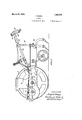
- FIG. 3 is a detail'of the clutch control mechanism and steering posts
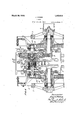
- Figure 4 is a horizontahsectionalview, showing the manner of mounting the clutch and its operating mechanism -and' the driving" connection with the crank-shaft of the machine, g V V 7 1 "Figure 5: is a vertical sectional view on the line 5.5 of Fig. 4:, r
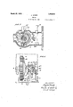
- Figure 6 is a plan view "showingin detall the lever mechanism for. operating'the clutch elements
- 'In the drawing 2representsthe' frame of the machine.
- 3 are the traction wheels therefor, provided with internal gear rings 4.
- '5 is-the crank shaft of the engine 6, mounted concentric with the hubs of the traction wheels and having fly wheels 7- and'a pulley 8 for the transmission of 'powento some other mechanism.
- 9 is a pinion secured on the crankshaft 5 and -10 is a hub-having "a ballbearing 'on a sleeve '11 and provided with a radial 'fiange 12 and gearJri-ng-IB which meshes with thete'eth'ofthe pinion9.
- This gear ring is in continuous :mesh with the pinion to be-revolved thereby.
- the flange 12 is provided with annular friction surfaces 14 and '15 encircled by thegear ring 13f and preferably integral "therewith.
- a frictionshoe 21 is :mounted on I the iShEItft' section 16 and hasa peripheral'fsurface'fto engage the :friction surface 14 of the gear ring and a hub 22 mounted; on thesleeve 11 has a friction shoe 23 'positioneolito.
- A'-rib 24 is formed on the sleeve 11- 'and a coiled spring 25 is interposed be tween this' rib and-a pin 26 which.
- a I coiled 'spring 2-29 encircles ;the spring25- and is interposed between i the pin 26 and a collar: 30 that is mounted :on the hub 22.
- a yoke 3l has a bearing'-at:32 in the machine frame and is providedwith pins 33'which'bear on a ring "34: through which pressure is transmitted to 1 the "ring 30 to press the spring' 29 against'rthe pin '26 and Withdraw the shoe :23 from contact Withthefriction-surface 15.
- This yoke is oscillatedby means of a crank 35.m0unted concentric with the pin 32and having a flexible connection 36 extending back" through' the machine frame and one of the steering posts 37 to a: rod- 38 that is mounted-in one of the handlebars 39' and provided with an operating lever'40 adjacent the hand grip 4L1.
- a yoke 46 mounted in the machine framein a manner corresponding to, the yoke 31 being pivoted at 46 and having a bearing at 47 (see Figure 6) on the inner face of the disc 28.
- a post 48 has an arm 49 connected by a link 50 with the yoke and a lever 51 is formed on said post and projects outwardly through the machine casing and has a flexible connection 52 with a rock shaft 53 thatis. mounted transversely of the machine in a yoke 54 for the purpose of carrying the operating mechanism of this clutch to the other side of the machine.
- the flexible connection 52 is attached to a crank 55 on one end of the shaft 53 and at the other end of said shaft is a pin 56 and a flexible connection 57 extending to a rock shaft 58 in the handle bar 39 and connected with the finger grip 59.
- the shaft 53 is rocked'and movement transmitted to the lever 51 to operate the yoke 46 and exert an outward pressure on the disc 28 and move the sleeve 11 and the gear ring and its shoe 14 to disengage it from the shoe 21, the sleeve 11 sliding on the pin 26 by reason of the longitudinal slot in the sleeve through which said pin projects.
- The'cu1tivator frame 60, the connection 61 with thesteering posts and the lever device 62 for supporting the steering posts'in their raised position are shown as parts of the machine but are not illustrated or described in detail, as they form no part of my present invention, being merely embodied in the general illustration to show the general principles of the tractor. u
- a traction machine comprising a frame, a source of motive power thereon, traction means for said' frame, a crank shaft operated from said source ofmotive power, a gear having a driving connection with said crankshaft and provided with clutching surfaces, clutch members having independ-, ent driving connection with said traction means and mounted to engage saidclutch surfaces respectively for driving said traction means from said gear, a steering'device for said frame, a hand grip'mounted on said steering device and mechanism connected with said hand grip for positively releasing one of said clutch members and subsequently positively releasing the other member.
- a traction machine comprising a frame, a source. of motive power thereon, traction wheels for said frame, a crank shaft operated from saidsource of motivepower', a gear having a driving connection with said crank shaft and provided with opposing friction surfaces, clutch members having independent driving connections with said traction wheels and mounted to engage saidfriction surfaces respectively, and a primary clutch control mounted to initially release one clutch member and subsequently release the other member, and a secondary clutch control'mounted to release said subsequently operated clutch member independently of said initially operated clutch member.
- a clutch comprising a driven gear having friction surfaces, frictionmembers for engaging said surfaces and shaft sections connected respectively with said friction members, and a control mechanism mounted on its initial movement to positively disengage one friction member from its friction surface and on its subsequent movement disengage the other friction member from its friction surface, a traction'niachine wherein said clutch is mounted, a steering postrfor said traction machine, a hand grip mounted on said steeringpost withinconvenient reach of the machine operator and inn means connecting said hand grip with said friction member control mechanism.
- a clutch comprising a driven gear having friction surfaces, friction members for engaging said surfaces and shaft sections,
- a clutch comprising a driven gear havmg frlction surfaces, a sleeve whereon said gear is loosely mounted, a clutch member mounted to engage one of said friction surfaces, a second clutch member mounted to engage the other friction surface, concentrically arranged springs for normally holding said clutch -members in contact with said friction surfaces, and a clutch control mounted on its initial movement to compress one of said springs and release one of said clutch members and on its subsequent movement to compress the other spring and release the other clutch member.
- a clutch comprising a driven gear having friction surfaces, a sleeve whereon said gear is loosely mounted, a clutch member mounted to engage one of said friction surfaces, a second clutch member mounted to engage the other friction surface, concentrically arranged springs for normally holding said clutch members in contact with said friction surfaces, and a clutch control mounted on its initial movement to compress one of said springs and release one of said clutch members and on its subsequent movement to compress the other spring and release the other clutch member, and a secondary clutch control for initially releasing said other clutch member independently of such first operated clutch member.
- a clutch comprising differential shaft sections, pinions mounted thereon, a clutch member secured to one of said shaft sections, a sleeve loosely mounted on the other shaft section, a disc mounted on said sleeve, a pin passing through said other shaft section and through slots provided in said sleeve for allowing longitudinal movement of said sleeve on said shaft section, said sleeve having a rib thereon, a coiled spring interposed between said pin and rib, a second clutch member loosely mounted on said sleeve, a spring interposed between said second clutch member and said pin, a gear loosely mounted on said sleeve between said clutch members and having friction surfaces for engagement with said clutch members, said springs normally holding said clutch members in engagement with said friction surfaces, a driving pinion meshing with said gear, a primary clutch control mounted on its initial movement to compress one of said springs and release one of said clutch members and onits subsequent movement to compress the other spring and release the other clutch member, and a secondary clutch control mounted to
- a traction machine comprising a-frame and traction means therefor, a source of motive power mounted on said frame having driving connections with said means and primary and secondary clutches for controllingsaid driving connections, steering posts mounted on said frame having hand grips and levers mountedthiereon, means iconnecting one of said levers through its steering post with said primary clutch, a pin mounted transversely in said frame to rock therein and connected at one end with said secondary clutch and having means for connection at its opposite end with the lever of the other steering post hand grip.
- a traction machine comprising a frame and traction means therefor, a source of motive power mounted on said frame and having driving connections with said means,
- a clutch comprising a driven gear having friction surfaces, a sleeve whereon said gear is loosely mounted, a clutch member mounted to engage one of said friction surfaces, a second clutch member mounted to engage the other friction surface, springs for normally holding said clutch members in contact with said friction surfaces, and a clutch control mounted on its initial movement to compress one of said springs and release one of said clutch members and on its subsequent movement to compress the other spring and release the other clutch member.
Landscapes
- Engineering & Computer Science (AREA)
- Chemical & Material Sciences (AREA)
- Combustion & Propulsion (AREA)
- Transportation (AREA)
- Mechanical Engineering (AREA)
- Mechanical Operated Clutches (AREA)
Description
March 20, 1928. 7 1,663,015
J. MADER CLUTCH Filed June 20, 1,919 4 Sheets-Sheet 2 March 20, 1928.
J. MADER CLUTCH Filed June 20, 1919 .4 Sheets-Sheet 3 [22 v e n 607* JOJEPH M17056 March '20, 1928. 7 1,663,015
J. MADER CLUTCH Filed June 20, 1919 4 Sheets-Sheet 4 Zn y en tar" gj-S'EF/l MHDER 7 is Hfitorneys.
Patented Mar. 20, 1928.
" UNITED smrss arana eerie-E. v
JOSEPH MADER, F MINNEAIEOLIS, MININESOTA, AS SIGNOR, BY MESNE ASSIGNMENTS,
TO NEWBEEMANTR-AG'IOR COMPANY, :OF MINNEABOLIS, MINNESOTA, -A,:CORIPOBA- IION OF'MINNESOTA.
' CLUTCH.
Application filed-Ju-nei20, 1'-919.-"'Seria1 No.*305,47e. I
the engine to thetraction'w-heels and so'constructed that eitherone-or both wheelsmay beldriven' from rsuchp'ower Afurth'er :and particular "object{ is to provide a clutch mechanisnnhaving "a con-trolling means whichwill. enable'the operator.
of "the" machine to easily and quickly manipulatethe clutch elements and positively control t'he'driving' of either traction Wheeh YA further object is to provid'ea clutch and control mechanism which, through itscompact and simple constructiomis particularly applicable to a tractor; of the "garden type that is steered by'a person walking in'the rear of .themachine. Theinvention consists generally-in various constructions and combinations-,=all as hereinafter described 'and particularly pointed out in the claims. r
In the accompanying :drawings forming part of thisspecification,
Figure 'l'i's 'aplan view of a traction mas chine with myinventi'on applied thereto,
Figure 2 is a verticalsectional view, showing the clutch control mechanism; andthe manner. of mountin'g'it in the steering-post of the machine,
Figure 3 is a detail'of the clutch control mechanism and steering posts,
Figure 4 is a horizontahsectionalview, showing the manner of mounting the clutch and its operating mechanism -and' the driving" connection with the crank-shaft of the machine, g V V 7 1 "Figure 5: is a vertical sectional view on the line 5.5 of Fig. 4:, r
Figure 6 is a plan view "showingin detall the lever mechanism for. operating'the clutch elements,
'In the drawing, 2representsthe' frame of the machine. 3 are the traction wheels therefor, provided with internal gear rings 4. '5 is-the crank shaft of the engine 6, mounted concentric with the hubs of the traction wheels and having fly wheels 7- and'a pulley 8 for the transmission of 'powento some other mechanism. 9 is a pinion secured on the crankshaft 5 and -10 is a hub-having "a ballbearing 'on a sleeve '11 and provided with a radial 'fiange 12 and gearJri-ng-IB which meshes with thete'eth'ofthe pinion9.
This gear ring is in continuous :mesh with the pinion to be-revolved thereby. The flange 12 is provided with annular friction surfaces 14 and '15 encircled by thegear ring 13f and preferably integral "therewith. :A shaft C'OIIl'pDSed of-sections l6 and .16 car-* riesjgthe sleeve 111 and one shaft section has a socket17wto"receive a stud 18:.f0rmed on the other section, said =istud-beinguheld against longitudinalmovementinzsaidisocket by pins l9 Which fit-into: an annular groove:
.20 'provided in the surface of -the stud. These pins, uwhile preventing longitudinal-imovement of the shaft sections 16 and lfifleallow them to'revolve one 'uponiithe other ifreely. A frictionshoe 21 is :mounted on I the iShEItft' section 16 and hasa peripheral'fsurface'fto engage the :friction surface 14 of the gear ring and a hub 22 mounted; on thesleeve 11 has a friction shoe 23 'positioneolito. engage the friction surface15 ofgthe gear .aring." The sleeve llqis free to slide for alimited distance onthesupporting shaft section 16 to'engage the friction surface 14withlthe shoe 21 and the'hub-22 has a'limited movement-on the sleeve llto engagelthe shoe-23 with the fr iction surface 15 or disengage it therefrom. A'-rib 24: is formed on the sleeve 11- 'and a coiled spring 25 is interposed be tween this' rib and-a pin 26 which. is inserted through a socket in the shaft sectionltli and' alsothrough{a sl0t 27 iin the sleeve 11 and near said pin on said sleeve is mounted a disc 28. A I coiled 'spring 2-29 encircles ;the spring25- and is interposed between i the pin 26 and a collar: 30 that is mounted :on the hub 22. A yoke 3l has a bearing'-at:32 in the machine frame and is providedwith pins 33'which'bear on a ring "34: through which pressure is transmitted to 1 the "ring 30 to press the spring' 29 against'rthe pin '26 and Withdraw the shoe :23 from contact Withthefriction-surface 15. This yoke is oscillatedby means of a crank 35.m0unted concentric with the pin 32and having a flexible connection 36 extending back" through' the machine frame and one of the steering posts 37 to a: rod- 38 that is mounted-in one of the handlebars 39' and provided with an operating lever'40 adjacent the hand grip 4L1. The initial move 'ment; ofthe lever 35, as heretofore mentione d,'compresses thespring 29 and releases the clutch shoe 23 which, through the sleeve iii.
11, keyed to the hub 22-at 42, drives the shaft section 16 and the pinion 43 which meshes with the internal gear ring of the traction wheel 3, the outward thrust movement. of such section 16 being taken up by the ball bearing 44 and the shoulder T rib 24 and move the sleeve 11 lengthwise on the shaft sections and disengagingthe friction surface from the shoe 21 and thereupon thev gear ring willrun idle without trans mitting power through either shoe to the traction wheels. Longitudinal movement of the sleeve 11 is permitted by reason of the slot 27 in the sleeve allowing the said sleeve to slide on the shaft section and be guided by the pin 26.
From the foregoing it is evident that initial movement ,of'the hand grip '40 and the lever disengages one friction shoe from the driving surface and continued movement of said leverdisengages the driving surface from the other friction shoe, the gear ring sliding on the teeth of the driving pinion a sufficient distance to permit such movement and release of the shoes.
It is also desirable to provide a means for disengaging the friction surface 14 and the shoe 21 without first releasing the shoe 23.- I therefore provide a yoke 46 mounted in the machine framein a manner corresponding to, the yoke 31 being pivoted at 46 and having a bearing at 47 (see Figure 6) on the inner face of the disc 28. A post 48 has an arm 49 connected by a link 50 with the yoke and a lever 51 is formed on said post and projects outwardly through the machine casing and has a flexible connection 52 with a rock shaft 53 thatis. mounted transversely of the machine in a yoke 54 for the purpose of carrying the operating mechanism of this clutch to the other side of the machine. The flexible connection 52 is attached to a crank 55 on one end of the shaft 53 and at the other end of said shaft is a pin 56 and a flexible connection 57 extending to a rock shaft 58 in the handle bar 39 and connected with the finger grip 59. When this finger grip is operated, the shaft 53 is rocked'and movement transmitted to the lever 51 to operate the yoke 46 and exert an outward pressure on the disc 28 and move the sleeve 11 and the gear ring and its shoe 14 to disengage it from the shoe 21, the sleeve 11 sliding on the pin 26 by reason of the longitudinal slot in the sleeve through which said pin projects. I am thus able with these two clutch controls to disengage one member of the clutch and release one traction wheel from its drive by the initial movement of the clutch control and then by subsequent movement release the other traction wheel ing connection between the other traction wheel and its shoe and the driving ring.
The'cu1tivator frame 60, the connection 61 with thesteering posts and the lever device 62 for supporting the steering posts'in their raised position are shown as parts of the machine but are not illustrated or described in detail, as they form no part of my present invention, being merely embodied in the general illustration to show the general principles of the tractor. u
I claim as my'invention:
1. A traction machine comprising a frame, a source of motive power thereon, traction means for said' frame, a crank shaft operated from said source ofmotive power, a gear having a driving connection with said crankshaft and provided with clutching surfaces, clutch members having independ-, ent driving connection with said traction means and mounted to engage saidclutch surfaces respectively for driving said traction means from said gear, a steering'device for said frame, a hand grip'mounted on said steering device and mechanism connected with said hand grip for positively releasing one of said clutch members and subsequently positively releasing the other member.
2. A traction machine comprising a frame, a source. of motive power thereon, traction wheels for said frame, a crank shaft operated from saidsource of motivepower', a gear having a driving connection with said crank shaft and provided with opposing friction surfaces, clutch members having independent driving connections with said traction wheels and mounted to engage saidfriction surfaces respectively, and a primary clutch control mounted to initially release one clutch member and subsequently release the other member, and a secondary clutch control'mounted to release said subsequently operated clutch member independently of said initially operated clutch member. I
3. A clutch comprising a driven gear having friction surfaces, frictionmembers for engaging said surfaces and shaft sections connected respectively with said friction members, and a control mechanism mounted on its initial movement to positively disengage one friction member from its friction surface and on its subsequent movement disengage the other friction member from its friction surface, a traction'niachine wherein said clutch is mounted, a steering postrfor said traction machine, a hand grip mounted on said steeringpost withinconvenient reach of the machine operator and inn means connecting said hand grip with said friction member control mechanism.
4:, A clutch comprising a driven gear having friction surfaces, friction members for engaging said surfaces and shaft sections,
- disengaging said initially released friction member.
5. A clutch comprising a driven gear havmg frlction surfaces, a sleeve whereon said gear is loosely mounted, a clutch member mounted to engage one of said friction surfaces, a second clutch member mounted to engage the other friction surface, concentrically arranged springs for normally holding said clutch -members in contact with said friction surfaces, and a clutch control mounted on its initial movement to compress one of said springs and release one of said clutch members and on its subsequent movement to compress the other spring and release the other clutch member.
6. A clutch comprising a driven gear having friction surfaces, a sleeve whereon said gear is loosely mounted, a clutch member mounted to engage one of said friction surfaces, a second clutch member mounted to engage the other friction surface, concentrically arranged springs for normally holding said clutch members in contact with said friction surfaces, and a clutch control mounted on its initial movement to compress one of said springs and release one of said clutch members and on its subsequent movement to compress the other spring and release the other clutch member, and a secondary clutch control for initially releasing said other clutch member independently of such first operated clutch member.
7. A clutch comprising differential shaft sections, pinions mounted thereon, a clutch member secured to one of said shaft sections, a sleeve loosely mounted on the other shaft section, a disc mounted on said sleeve, a pin passing through said other shaft section and through slots provided in said sleeve for allowing longitudinal movement of said sleeve on said shaft section, said sleeve having a rib thereon, a coiled spring interposed between said pin and rib, a second clutch member loosely mounted on said sleeve, a spring interposed between said second clutch member and said pin, a gear loosely mounted on said sleeve between said clutch members and having friction surfaces for engagement with said clutch members, said springs normally holding said clutch members in engagement with said friction surfaces, a driving pinion meshing with said gear, a primary clutch control mounted on its initial movement to compress one of said springs and release one of said clutch members and onits subsequent movement to compress the other spring and release the other clutch member, and a secondary clutch control mounted to engage said disc and release one of said clutch members independ-' ently of the other clutch member.
8. A traction machine comprising a-frame and traction means therefor, a source of motive power mounted on said frame having driving connections with said means and primary and secondary clutches for controllingsaid driving connections, steering posts mounted on said frame having hand grips and levers mountedthiereon, means iconnecting one of said levers through its steering post with said primary clutch, a pin mounted transversely in said frame to rock therein and connected at one end with said secondary clutch and having means for connection at its opposite end with the lever of the other steering post hand grip.
9. A traction machine comprising a frame and traction means therefor, a source of motive power mounted on said frame and having driving connections with said means,
and primary and secondary clutches for controlling said driving connections, steering posts mounted on said frame and having hand grips and levers mounted thereon, means connecting one of said levers through its steering post with one of said clutches and means mounted transversely of said frame to rock therein and connected with the other clutch and having means for connection with the other steering post lever.
10. A clutch comprising a driven gear having friction surfaces, a sleeve whereon said gear is loosely mounted, a clutch member mounted to engage one of said friction surfaces, a second clutch member mounted to engage the other friction surface, springs for normally holding said clutch members in contact with said friction surfaces, and a clutch control mounted on its initial movement to compress one of said springs and release one of said clutch members and on its subsequent movement to compress the other spring and release the other clutch member.
In witness whereof, I have hereunto set my hand this 7 day of June, 1919.
JOSEPH MADER.
Priority Applications (1)
| Application Number | Priority Date | Filing Date | Title |
|---|---|---|---|
| US305474A US1663015A (en) | 1919-06-20 | 1919-06-20 | Clutch |
Applications Claiming Priority (1)
| Application Number | Priority Date | Filing Date | Title |
|---|---|---|---|
| US305474A US1663015A (en) | 1919-06-20 | 1919-06-20 | Clutch |
Publications (1)
| Publication Number | Publication Date |
|---|---|
| US1663015A true US1663015A (en) | 1928-03-20 |
Family
ID=23180956
Family Applications (1)
| Application Number | Title | Priority Date | Filing Date |
|---|---|---|---|
| US305474A Expired - Lifetime US1663015A (en) | 1919-06-20 | 1919-06-20 | Clutch |
Country Status (1)
| Country | Link |
|---|---|
| US (1) | US1663015A (en) |
-
1919
- 1919-06-20 US US305474A patent/US1663015A/en not_active Expired - Lifetime
Similar Documents
| Publication | Publication Date | Title |
|---|---|---|
| US1772247A (en) | Power take-off | |
| US2237322A (en) | Clutch mechanism | |
| US2410921A (en) | Power transmission device | |
| US1663015A (en) | Clutch | |
| US2465054A (en) | Clutch operating mechanism | |
| US2988185A (en) | Power drive mechanism | |
| US2014383A (en) | Power transmission mechanism | |
| US1338777A (en) | Transmission | |
| US2105680A (en) | Tractor | |
| US1993405A (en) | Tractor | |
| US1388324A (en) | Change speed mechanism | |
| US617332A (en) | Motor-vehicle | |
| US2596053A (en) | Coordinated clutch and brake control for vehicle driving mechanism | |
| US1305866A (en) | Fbiction-dbive | |
| DE537411C (en) | Drive and steering device for caterpillar vehicles | |
| US1467681A (en) | Clutch-controlling means | |
| US1935414A (en) | Motor vehicle braking device | |
| US1679584A (en) | Control unit | |
| US1312609A (en) | Tsaitsmissioh mechanism | |
| US1290266A (en) | Tractor transmission mechanism for motor-vehicles. | |
| US1416539A (en) | Tractor | |
| US1673795A (en) | Power-transmission mechanism | |
| US1400684A (en) | Tractor | |
| US2256822A (en) | Tractor | |
| US1493401A (en) | Attachment for tractors |