US1663012A - Centrifugal brake mechanism - Google Patents
Centrifugal brake mechanism Download PDFInfo
- Publication number
- US1663012A US1663012A US188090A US18809027A US1663012A US 1663012 A US1663012 A US 1663012A US 188090 A US188090 A US 188090A US 18809027 A US18809027 A US 18809027A US 1663012 A US1663012 A US 1663012A
- Authority
- US
- United States
- Prior art keywords
- arms
- arm
- levers
- weighted
- lever
- Prior art date
- Legal status (The legal status is an assumption and is not a legal conclusion. Google has not performed a legal analysis and makes no representation as to the accuracy of the status listed.)
- Expired - Lifetime
Links
- 230000007246 mechanism Effects 0.000 title description 19
- 238000003825 pressing Methods 0.000 description 9
- 238000005192 partition Methods 0.000 description 5
- 238000006073 displacement reaction Methods 0.000 description 4
- 229910000831 Steel Inorganic materials 0.000 description 2
- 239000010959 steel Substances 0.000 description 2
- 241001591024 Samea Species 0.000 description 1
- 230000006978 adaptation Effects 0.000 description 1
- 238000005452 bending Methods 0.000 description 1
- 238000010276 construction Methods 0.000 description 1
- 239000010985 leather Substances 0.000 description 1
- 239000000463 material Substances 0.000 description 1
- 239000012858 resilient material Substances 0.000 description 1
- 230000000717 retained effect Effects 0.000 description 1
- 238000004804 winding Methods 0.000 description 1
Images
Classifications
-
- F—MECHANICAL ENGINEERING; LIGHTING; HEATING; WEAPONS; BLASTING
- F16—ENGINEERING ELEMENTS AND UNITS; GENERAL MEASURES FOR PRODUCING AND MAINTAINING EFFECTIVE FUNCTIONING OF MACHINES OR INSTALLATIONS; THERMAL INSULATION IN GENERAL
- F16D—COUPLINGS FOR TRANSMITTING ROTATION; CLUTCHES; BRAKES
- F16D59/00—Self-acting brakes, e.g. coming into operation at a predetermined speed
Definitions
- the invent-ion relates to an improvement in centrifugal brake mechanisms and especially to brake mechanisms useful in connection With a fire escape or in any similar connection Where a drop is eected and a centrifugal brake mechanism is employed'to govern the speed ofthe drop.
- the essential ob 'ect of the invention is to make the brake mechanism not only edect'ive in its operation, but essentially also a safe mechanism or one that will properly respond to all demands upon it and' especially sudden strains and Wil-l not so tighten or bind under any circumstance as to cause breakage in any of its operating parts or ⁇ parts affecting its operation.
- Fig.. 2 is a cross sectionon.V the line 2--2 of Fig. -1 showing especially a front elevation of the brake mechanism.
- FIG. 3 is a. rear elevation. of the brake Y mechanism shown in Fig. 2, and
- Fig. et is a front elevation of a. detail ofv construction. to which reference Will later be made.
- the body of the device comprises outer casing members 1 and 2 ⁇ and aV partitionforming member 3 which occupies. a position interior the outer casing members 1 and 2 and spaced therefrom respectively.
- several members 1, 2 and 3 are fastened rigidly together by means of rim flanges with which the several members are provided', the member 1 being provided With arim flange 4, the member 2 with a rimflange 5 and the member 3 with a rim flange 6.
- a spindle 8 Centrally mounted tov turn axially on the outer casing members With bearing thereon and Withextension through the interior partition member is a spindle 8.
- the spindle is retained against endrvise displacement by CENTRHUGAL BRAKE. MncHANrsia.
- part 9' ofthe crank is securedjto the end of 55 ing against the interior face ofthe casing, it
- The-crank' comprisesY the farm 9*, ⁇ previously referred to, 70 which 1s provided with a hinged extension 12T bearing a hand gripv 13 byWhich the crankis turned when the arm extension l12 is extended.
- the adaptation of the arm: eX- tensifon 12 isv such' that When ⁇ not in use it 75' Will' fold against the arm- 9, and the hand" grip 1'3on the end of the extension will enter and become socketed Wit-hin the spindle,' l preferably made hollow.
- the arm extension 12 is also preferably provided With a cover ⁇ 80 '14 Which.
- the inner face ofthe drumll is providedv with a. recess- 17 and' is alsoprovided onl diametrically opposite sides of the spindile with openings I8..
- vvvith extensionA into therecess- 17 of thedrum, are pins v 19, 19'.
- Each of these. pi-ns isV backed by a spring 20 by means of which the pins have al normal outward projection.
- y j gagement for turning a Wheel 21 Whichy loosely embraces the spindle 8 and is mountY ed to turn Within the cavity provided by ⁇ the partition member 3 and its rim Harige 6.
- the pins 19 have. enloofnally toothed rim lange 23. ln engagement
- the engagement of the pins with the Wheel 2l for turning it is such that the pins engage the wheel only when the drum to which the steel tape is secured is moving or being turned in a counterclockwise, direction. That is, the engagementv of the drum with the wheel 2l through the interposed pins is such as will permit of the spindle bein rotated manually by the crank l0 in awise direction for winding the tape upon the drum without disturbing the wheel 2l, but rotation of the wheel 2l will be obtained as the drum ismoved in a reverse or counterclockwise ydirection by the unwinding of the tape.
- the wheel'21 is provided with an interwith the teeth of this-flange is a pinion gear 24 which is mounted to turn on a fixed boss V25 projecting outwardly Vfromgthe side of the partition member 3.
- a gear 26 arranged to turn y upon the spindle 8 and provided with a tri-V angular-shaped gear piece 27 which extends along the spindle into the chamber containing the brake mechanism, and by which gear piece the mechanism is actuated, as will presently be explained.
- thegear 2l is turned in the operation of the device upon the unwinding of the tape 15 the motion thereof will be transmitted throughthe pinion gear 24 to the gear 26 and thence through the gear piece 27 forming a part or side extension of the gear 26 for actuating the brake mechanism.
- the brake 'mechanism comprises a number of parts located within a chamber Vvformed between the casing member 2 and the partition '3 and bounded exteriorly by the annular rim 5 of the casing member 2.
- the brake mechanism comprises triangularshaped centerpiece 30 adapted to receive the triangular-shaped gear piece 27 which-projects from the gear 26'.
- -The kcenterpiece 30 is provided with three radiating arms V31,
- the arm 33 has plvoted to it by a pin 45 a lever having arms 46 and 47, respectively, and also a lever having that as the brake mechanism is rotated these arms by reason of their weighting will be thrown outwardly by the action of centrifugal force, causing the levers to turn on their pivotal connections and moving the several arms 37, 43 and 4 8 forming a part of these sameA levers of whichv the weighted arms form a part.
- coiled springs 5l Secured to each of the weighted arms 38, 44 and 49, respectively, are coiled springs 5l which connect respectively with the other levers.
- the spring 5l connected to the weighted lever arm 38 is connected to the lever arm 47
- the spring 5l connected to the weighted arm 44 is connectedy to the lever arm 36
- the spring/51 connected to the weighted lever arm 49 is connected to the lever arm 42.
- the lever arm 37 is adapted to receive and hold an end 55 of the braking strip 52, whileV the opposite end 56 of this strip is received and held by the lever arm 4l.
- the end 57 of the braking strip 53' is receivedl and held by the lever arm 43, while'the op-v posite end 58V of this strip is received and held by the lever aim 46.
- the end 59 of the strip 54 is received and held by the lever arm 48, while the opposite end 60 of this strip is received and held by the lever arm 35.
- the strip 52 will be compressed by motion of the arms 37 and 4l being actuated to move toward one another, the arm 37 being moved directly by the weighted arm 38 and the arm 4l being moved indirectly by the weighted arm 49 through the spring connecting with the arm 42; the strip 53 will be compressed by movement of the arms 43 and 46 which are actuated to move ltoward one another, the arm 43 being moved directly by the weighted arm 44 and the arm 46r being moved indirectly by the weighted arm 38 through the spring connecting with the arm 47; and the spring 54 will be compressed by movement of the lever arms48 and 35 respectively toward one another, the arm 48 being moved directly by the Weighted arm 49 and the arm 35 being moved indirectly by the weighted arm 44 through the spring connecting with the lever arm 36.
- the manner of application of pressure to the opposite ends of the brake strips for bending or distorting them is preferably such that the lever arms for applying pressure, actuated directly by the weighted arms, will operate against the rear ends of the strips and the arms for applying pressure, which arev actuated indirectly by the weighted arms through the spring connections, will operate against the forward ends of the brake strips.
- this entire mechanism will, by the rotation of the centerpiece 30, be rotated in a clockwise direction and accordingly the arms 37, 43 and 48 respectively, which are operated directly by the weighted arms, will bear against the rear ends of the respective strips 52, 53 and 54.
- the arms 41, 46 and 35 whichare operated indirect-ly by weighted arms through the spring connections, will bear directly against the forward ends of the respective brake strips 52, 53 and 54.
- the ⁇ v combina-.tion comprising an exterior casing
- a number of flexible brake'y stripsA each ar-v rangedto frictionally engage the interior of the casing when distorted by: the applica@ ⁇ tion of pressure to its opposite ends, a rotary centerpiece wit-hin the casing having arms, means for rotating the centerpiece, levers ypivoted to the arms of the centerpiece and connected respectively to said strips at one end thereof for applying pressure tl1ereto as said levers are operated, each of said levers having a weighted arm displaceable outwardly by centirfugal force when said centerpiece is rotated and by the displacement of which weighted arm the lever is operated, other levers pivoted to said arms of the centerpiece and connected respectivef ly to the other ends of said strips for applying pressure thereto as said other levers are operated, and means whereby said other levers will be operated by the weighted arms of the levers first mentioned.
- a rotary centerpiece within the casing having arms, means for rotating the centerpiece, levers pivoted to the armsof the centerpiece and connected respectively to said strips at one end thereof for applying pressure thereto as said levers are operated, each of said levers having a weighted arm displaceable outwardly byl centrifugal force when said centerpiece is rotated and by the displacement of which weighted arm the lever is operated, other levers pivoted to said arms of the centerpiece and connected respectively to the other ends of said strips for applying pressure thereto as said other levers are operated, and springs connecting arms of said other levers to the Weighted arms of the levers first mentioned whereby said other levers will be operated by the weighted arms for applying pressure to said other ends of the strips as said Weighted arms are displaced outwardly as aforesaid.
- a centrifugal brake mechanism comprising an exterior casing, a number of flexible brake strips each arranged to frictionally engage the interior of the casing when distorted by the application of pressure to its opposite ends, a rotary centerpiece within the casing having arms,
- levers v having weighted armsl displaceable' outwardly by centrifugal force when said centerpiece is rotated and by the displacement of which weighted arm the lever isv op- 5 erated, other levers pivoted to *the arms of v thecenterpiece and connected respectively to the forward ends of said strip for applying pressure thereto'as'said levers are operated,
Landscapes
- Engineering & Computer Science (AREA)
- General Engineering & Computer Science (AREA)
- Mechanical Engineering (AREA)
- Braking Arrangements (AREA)
Description
March 20, 1928. Y
` L. LANDRY CENTRTFUGAL `BRAKE MEcHANlsM vFiled May '2, 1927` IIIIIII Patented Mar. Z0, 1928.
UNITE' LOUIS LANDRY, 0F BERWICK, MAINE.
Application lec May 2,
The invent-ion relates to an improvement in centrifugal brake mechanisms and especially to brake mechanisms useful in connection With a fire escape or in any similar connection Where a drop is eected and a centrifugal brake mechanism is employed'to govern the speed ofthe drop.
The essential ob 'ect of the invention is to make the brake mechanism not only edect'ive in its operation, but essentially also a safe mechanism or one that will properly respond to all demands upon it and' especially sudden strains and Wil-l not so tighten or bind under any circumstance as to cause breakage in any of its operating parts or` parts affecting its operation.
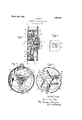
The invention can best'be seen and under stood by reference to the drawings in* wl1i`ch` Y Figure 1 is a view thereof in 'cross see-` tional elevation. f
Fig.. 2 is a cross sectionon.V the line 2--2 of Fig. -1 showing especially a front elevation of the brake mechanism.
3 is a. rear elevation. of the brake Y mechanism shown in Fig. 2, and
Fig. et is a front elevation of a. detail ofv construction. to which reference Will later be made. i
Referring to the drawings.:-
The body of the device. comprises outer casing members 1 and 2` and aV partitionforming member 3 which occupies. a position interior the outer casing members 1 and 2 and spaced therefrom respectively. rlihe several members 1, 2 and 3 are fastened rigidly together by means of rim flanges with which the several members are provided', the member 1 being provided With arim flange 4, the member 2 with a rimflange 5 and the member 3 with a rim flange 6. The fastening together or combining of the respective members vis obtainedv by fastening the rim fianges i andf of t-he outer casing members to the rim flange 6 of the partition member and which fastening is made by means of screws 7.
Centrally mounted tov turn axially on the outer casing members With bearing thereon and Withextension through the interior partition member is a spindle 8. The spindle is retained against endrvise displacement by CENTRHUGAL BRAKE. MncHANrsia.
1927. Serial NTO.V 185,090. l
means of an. arm 9 forming a part ofl a crank l0' by which the spindle is turned. The
part 9' ofthe crank is securedjto the end of 55 ing against the interior face ofthe casing, it
will' operate to prevent outward displace-4 ment of the spindle.
lt isby means of the crank 10 that the spindle is turned manually. The-crank'comprisesY the farm 9*,` previously referred to, 70 which 1s provided with a hinged extension 12T bearing a hand gripv 13 byWhich the crankis turned when the arm extension l12 is extended. The adaptation of the arm: eX- tensifon 12 isv such' that When` not in use it 75' Will' fold against the arm- 9, and the hand" grip 1'3on the end of the extension will enter and become socketed Wit-hin the spindle,' l preferably made hollow. The arm extension 12 is also preferably provided With a cover `80 '14 Which. When the arm extension is fol'd'edf as aforesaid' will engage the Aside of the casmg member 1 'and envelop the entire crank. Fastened to the drum 11 is the inner end ofa steel tape-15 which is adapted' to be 85 Wound' or coiled' upon the drum'as the spindle is turned by the operation ofi-the crank for turning.; the drum1 or the tape may be unvvound from the drum in the operationof the device for actuating the Working parts thereof a-s will later be explained; i
The inner face ofthe drumll is providedv with a. recess- 17 and' is alsoprovided onl diametrically opposite sides of the spindile with openings I8.. Within these open-ings, vvvith extensionA into therecess- 17 of thedrum, are pins v 19, 19'. Each of these. pi-ns isV backed by a spring 20 by means of which the pins have al normal outward projection. y j gagement for turning a Wheel 21 Whichy loosely embraces the spindle 8 and is mountY ed to turn Within the cavity provided by` the partition member 3 and its rim Harige 6.
Slidably mounted i The pins 19 have. enloofnally toothed rim lange 23. ln engagement The engagement of the pins with the Wheel 2l for turning it is such that the pins engage the wheel only when the drum to which the steel tape is secured is moving or being turned in a counterclockwise, direction. That is, the engagementv of the drum with the wheel 2l through the interposed pins is such as will permit of the spindle bein rotated manually by the crank l0 in awise direction for winding the tape upon the drum without disturbing the wheel 2l, but rotation of the wheel 2l will be obtained as the drum ismoved in a reverse or counterclockwise ydirection by the unwinding of the tape. The engagement between the pins and wheel is secured by means of clutch members 22 formed on the outer face of the wheel 2l, the form of the-clutch members being such that the pins will ride over them as the drum carying thepins is moved in a clockwise direction, or thev pins will engage the clutch members for turning the wheel 21 as the drum moves inA a reverse or counterclockwise direction. I i
The wheel'21 is provided with an interwith the teeth of this-flange is a pinion gear 24 which is mounted to turn on a fixed boss V25 projecting outwardly Vfromgthe side of the partition member 3. Meshing with the vpinion gear 24 is a gear 26 arranged to turn y upon the spindle 8 and provided with a tri-V angular-shaped gear piece 27 which extends along the spindle into the chamber containing the brake mechanism, and by which gear piece the mechanism is actuated, as will presently be explained. In otherwords, as
thegear 2l is turned in the operation of the device upon the unwinding of the tape 15 the motion thereof will be transmitted throughthe pinion gear 24 to the gear 26 and thence through the gear piece 27 forming a part or side extension of the gear 26 for actuating the brake mechanism.
'The brake 'mechanism comprises a number of parts located within a chamber Vvformed between the casing member 2 and the partition '3 and bounded exteriorly by the annular rim 5 of the casing member 2. The brake mechanism comprises triangularshaped centerpiece 30 adapted to receive the triangular-shaped gear piece 27 which-projects from the gear 26'. -The kcenterpiece 30 is provided with three radiating arms V31,
.32 and 33, respectively, arranged equidistant fromV one another.l Pivoted to the ends of each of thesearms are sets of separate levers which are Valike for all ofk the arms. Thus lthe arm 31 has pivoted to it by a pin 34 a lever having arms 35 and 36, respectively, andalso a lever having arms 37 and 38, respectively, the same pin 34 serving` as the pivotal `support for both levers. Likewise the arm has pivoted to it by a pin 40 a lever having arms 4l and'42, respectively, and also a lever having arms 43 and 44, respectively, the same pin 40 serving as a pivotal connection for both levers. In similar manner the arm 33 has plvoted to it by a pin 45 a lever having arms 46 and 47, respectively, and also a lever having that as the brake mechanism is rotated these arms by reason of their weighting will be thrown outwardly by the action of centrifugal force, causing the levers to turn on their pivotal connections and moving the several arms 37, 43 and 4 8 forming a part of these sameA levers of whichv the weighted arms form a part. Secured to each of the weighted arms 38, 44 and 49, respectively, are coiled springs 5l which connect respectively with the other levers. Thus the spring 5l connected to the weighted lever arm 38 is connected to the lever arm 47 Likewise the spring 5l connected to the weighted arm 44 is connectedy to the lever arm 36 and the spring/51 connected to the weighted lever arm 49 is connected to the lever arm 42. nWith the conn-ections thus made by means of the interposed springs, as the weighted lever arms are thrown outwardly by the action of centrifugal force a pull willy bey eX- erted through the several springs upon the several arms 47, 36 and 42, drawing these arms outwardly and moving the several lever arms 46, 35 and 41 forming a part of the same levers. The springs 5l also assist .inrmaintaining all the levers in a normal retracted position. Y
52, 53 and 54, respectively, represent curved braking strips of a resilient material and covered with a facing of leather or other frictional material. These braking strips are arranged just inside the interior face of. the rim 5 of the casing member' 2, and'in theoperation of the brake mechamsm are adapted to be thrown into Contact with the interior surface of the rim 5 and thereby operatea's ar braking medium for impeding the rotation of the brake `mechanism. The displacing of these curved braking strips to engage the rim '5 is effected by distorting orbending the strips by an application of pressure to the opposite ends thereof which tends, owing to the pressure the Aseveral levers having jaws upon their ends which receive and hold the ends of the iesgoaia? the lever arm 37 is adapted to receive and hold an end 55 of the braking strip 52, whileV the opposite end 56 of this strip is received and held by the lever arm 4l. Likewise the end 57 of the braking strip 53' is receivedl and held by the lever arm 43, while'the op-v posite end 58V of this strip is received and held by the lever aim 46. ln similar manner the end 59 of the strip 54 is received and held by the lever arm 48, while the opposite end 60 of this strip is received and held by the lever arm 35.
W'ith the lever arms thus arranged and connected to the ends of the brake strips, all the strips will become bent or distorted to engage the rim 5 of the casing member 2 by pressure applied from the opposite ends of the strips as the weighted arms 38, 44 and 49 are thrown outwardly by centrifugal force as the centerpiece is rotated. The strip 52 will be compressed by motion of the arms 37 and 4l being actuated to move toward one another, the arm 37 being moved directly by the weighted arm 38 and the arm 4l being moved indirectly by the weighted arm 49 through the spring connecting with the arm 42; the strip 53 will be compressed by movement of the arms 43 and 46 which are actuated to move ltoward one another, the arm 43 being moved directly by the weighted arm 44 and the arm 46r being moved indirectly by the weighted arm 38 through the spring connecting with the arm 47; and the spring 54 will be compressed by movement of the lever arms48 and 35 respectively toward one another, the arm 48 being moved directly by the Weighted arm 49 and the arm 35 being moved indirectly by the weighted arm 44 through the spring connecting with the lever arm 36.
The manner of application of pressure to the opposite ends of the brake strips for bending or distorting them is preferably such that the lever arms for applying pressure, actuated directly by the weighted arms, will operate against the rear ends of the strips and the arms for applying pressure, which arev actuated indirectly by the weighted arms through the spring connections, will operate against the forward ends of the brake strips. In other words, looking at the brake mechanism as illustrated in Fig. 2, this entire mechanism will, by the rotation of the centerpiece 30, be rotated in a clockwise direction and accordingly the arms 37, 43 and 48 respectively, which are operated directly by the weighted arms, will bear against the rear ends of the respective strips 52, 53 and 54. On the otherV hand, the arms 41, 46 and 35, whichare operated indirect-ly by weighted arms through the spring connections, will bear directly against the forward ends of the respective brake strips 52, 53 and 54. i
Having thus-y fullyl-describedimy inver.'-A
tion, I claim and desiretonsecureby Letters VPatent ofthe Unitedv States :-1
1.' In a centrifugal brake mechanism, the`v combina-.tion comprising an exterior casing,
a number of flexible brake'y stripsA each ar-v rangedto frictionally engage the interior of the casing when distorted by: the applica@` tion of pressure to its opposite ends, a rotary centerpiece wit-hin the casing having arms, means for rotating the centerpiece, levers ypivoted to the arms of the centerpiece and connected respectively to said strips at one end thereof for applying pressure tl1ereto as said levers are operated, each of said levers having a weighted arm displaceable outwardly by centirfugal force when said centerpiece is rotated and by the displacement of which weighted arm the lever is operated, other levers pivoted to said arms of the centerpiece and connected respectivef ly to the other ends of said strips for applying pressure thereto as said other levers are operated, and means whereby said other levers will be operated by the weighted arms of the levers first mentioned.
2. In a centrifugal brake mechanism, the combination comprising an exterior casing,
of the casing when distorted by the application of pressure to its opposite ends, a rotary centerpiece within the casing having arms, means for rotating the centerpiece, levers pivoted to the armsof the centerpiece and connected respectively to said strips at one end thereof for applying pressure thereto as said levers are operated, each of said levers having a weighted arm displaceable outwardly byl centrifugal force when said centerpiece is rotated and by the displacement of which weighted arm the lever is operated, other levers pivoted to said arms of the centerpiece and connected respectively to the other ends of said strips for applying pressure thereto as said other levers are operated, and springs connecting arms of said other levers to the Weighted arms of the levers first mentioned whereby said other levers will be operated by the weighted arms for applying pressure to said other ends of the strips as said Weighted arms are displaced outwardly as aforesaid.
3. ln a centrifugal brake mechanism, lthe combination Vcomprising an exterior casing, a number of flexible brake strips each arranged to frictionally engage the interior of the casing when distorted by the application of pressure to its opposite ends, a rotary centerpiece within the casing having arms,
ion
mea-ns for rotating the centerpiece, levers v having weighted armsl displaceable' outwardly by centrifugal force when said centerpiece is rotated and by the displacement of which weighted arm the lever isv op- 5 erated, other levers pivoted to *the arms of v thecenterpiece and connected respectively to the forward ends of said strip for applying pressure thereto'as'said levers are operated,
andltension means connecting arms of said other levers to the weighted arms of the levers lirst mentioned whereby said other levers will be operated by the weighted arms for applying pressure to the forward ends of said strips as said weighted arms are placed outwardly as aforesaid.
LOUIS LANDRY,
dsi
Priority Applications (1)
| Application Number | Priority Date | Filing Date | Title |
|---|---|---|---|
| US188090A US1663012A (en) | 1927-05-02 | 1927-05-02 | Centrifugal brake mechanism |
Applications Claiming Priority (1)
| Application Number | Priority Date | Filing Date | Title |
|---|---|---|---|
| US188090A US1663012A (en) | 1927-05-02 | 1927-05-02 | Centrifugal brake mechanism |
Publications (1)
| Publication Number | Publication Date |
|---|---|
| US1663012A true US1663012A (en) | 1928-03-20 |
Family
ID=22691739
Family Applications (1)
| Application Number | Title | Priority Date | Filing Date |
|---|---|---|---|
| US188090A Expired - Lifetime US1663012A (en) | 1927-05-02 | 1927-05-02 | Centrifugal brake mechanism |
Country Status (1)
| Country | Link |
|---|---|
| US (1) | US1663012A (en) |
Cited By (1)
| Publication number | Priority date | Publication date | Assignee | Title |
|---|---|---|---|---|
| US20110073404A1 (en) * | 2009-09-30 | 2011-03-31 | Gm Global Technology Operations, Inc. | Electric Power Steering System Over-Speed Energizing Brake System |
-
1927
- 1927-05-02 US US188090A patent/US1663012A/en not_active Expired - Lifetime
Cited By (2)
| Publication number | Priority date | Publication date | Assignee | Title |
|---|---|---|---|---|
| US20110073404A1 (en) * | 2009-09-30 | 2011-03-31 | Gm Global Technology Operations, Inc. | Electric Power Steering System Over-Speed Energizing Brake System |
| US8177018B2 (en) * | 2009-09-30 | 2012-05-15 | GM Global Technology Operations LLC | Electric power steering system over-speed energizing brake system |
Similar Documents
| Publication | Publication Date | Title |
|---|---|---|
| US447780A (en) | Gar brake and starter | |
| US1663012A (en) | Centrifugal brake mechanism | |
| US4182197A (en) | Railroad car hand brake | |
| US1572635A (en) | Window-regulator lock | |
| US1272361A (en) | Line-reel. | |
| US2026665A (en) | Reel | |
| US1502018A (en) | Internal-combustion-engine starter | |
| US1938885A (en) | Hand brake for railway cars | |
| US2954209A (en) | Winch | |
| JPH0226941B2 (en) | ||
| US2855722A (en) | Drive for toy vehicles | |
| US1341102A (en) | Toy band-wagon | |
| US2457764A (en) | Hand brake | |
| US1406005A (en) | Fishing reel | |
| US2121095A (en) | Combined clutch and friction retarding means for hand brakes | |
| US2222766A (en) | Automatic change speed transmission | |
| US1832189A (en) | Lineswitch driving arrangement for motor and hand operation | |
| US1475815A (en) | Starter for explosive engines | |
| US1948886A (en) | Fishing reel | |
| US1653948A (en) | Brake | |
| US1482715A (en) | Expanding ring clutch | |
| US2492080A (en) | Hand brake | |
| US1097419A (en) | Engine-starter. | |
| US1844345A (en) | Brake | |
| JPH08303496A (en) | Centrifugal brake and window opening / closing device |