US1663001A - Spring seat construction - Google Patents
Spring seat construction Download PDFInfo
- Publication number
- US1663001A US1663001A US189960A US18996027A US1663001A US 1663001 A US1663001 A US 1663001A US 189960 A US189960 A US 189960A US 18996027 A US18996027 A US 18996027A US 1663001 A US1663001 A US 1663001A
- Authority
- US
- United States
- Prior art keywords
- wall
- spring seat
- rim
- base
- seat construction
- Prior art date
- Legal status (The legal status is an assumption and is not a legal conclusion. Google has not performed a legal analysis and makes no representation as to the accuracy of the status listed.)
- Expired - Lifetime
Links
- 238000010276 construction Methods 0.000 title description 9
- 239000000463 material Substances 0.000 description 11
- 239000002184 metal Substances 0.000 description 7
- 238000003466 welding Methods 0.000 description 5
- 239000002023 wood Substances 0.000 description 3
- 230000027455 binding Effects 0.000 description 1
- 238000009739 binding Methods 0.000 description 1
- 239000000945 filler Substances 0.000 description 1
- 238000004519 manufacturing process Methods 0.000 description 1
- 210000002105 tongue Anatomy 0.000 description 1
Images
Classifications
-
- A—HUMAN NECESSITIES
- A47—FURNITURE; DOMESTIC ARTICLES OR APPLIANCES; COFFEE MILLS; SPICE MILLS; SUCTION CLEANERS IN GENERAL
- A47C—CHAIRS; SOFAS; BEDS
- A47C31/00—Details or accessories for chairs, beds, or the like, not provided for in other groups of this subclass, e.g. upholstery fasteners, mattress protectors, stretching devices for mattress nets
- A47C31/02—Upholstery attaching means
Definitions
- This invention relates to spring seat constructions, and more particularly to metal rims for same.
- the object of the invention is to provide a rim-defining the outline of the bottom of may be secured by spot welding.
- Another object is to obviate the necessityfor using a gimp or bin-ding for the upholstery material, by providing a tacking strip at the bottom of the rim.
- Another object of the invention 18 to produce a simple and durable device which w1ll require the minimum of labor for the upholsterer to perform when attaching the upholstery material thereto and which Wlll give a neat and finished appearance to the cushion when completed.
- Figure 1 is a perspective View of my improved rim, showing part of a conventional grille base attached thereto.
- Figure 2 is a sectional View of the run, enlarged, showing the upholstery material attached to the wooden insert of the rim, and a grille base with part of a spring thereon.
- Figure 3 is a bottom plan of the rim strip, also enlarged.
- A represents the rim as a whole
- B is the grille base
- C is a spring thereon
- D the upholstery material.
- the rim A is made of a strip of metal, constituting the vertical wall 1, bent longitudinally back upon itself to form the vertical wall 2, of less height than the wall 1, then bent at right angles to form a horizontally disposed wall 3, a vertical wall 4, and a short bottom wall 5.
- a filler, or insert of wood or other suitable material, indicated at 6, is securely held between the walls 2, 3, 4'and 5.
- the bottom 5 is pressed up againstthe' inse-rte, so as to slightly bite into the wood or other material.
- the border wire 7 ofthegri-lle base 13 is supported-upon the top wall 3 and rests against the inner surface of the wall. 1, and, lSfCOIlIlBClEBCllZO the rim A by-spot Welding, indicated-at 8 on Figure 1.
- the upholstery material 1) is brought downwardly over the front of the cushion and arranged-over the sniootli,-rounded edge 9 ofthe metal rim;A,and-theedge 10 of the material D, in-turned if desired, is securely tacked to the insert 6 by'taok 11.
- the smooth front surface of the wall 1 extending considerably above the wall 4t presents a desirable backing for the upholstery material and prevents it from wearing out.
- the wall 1 extends sufficiently above the grille base B to hold the upholstery material away from the grille wire and. the body springs, which would otherwise rubagainst it and produce wear.
- a base frame comprising a metallic member bent longitudinally between its margins to form a vertically disposed outwardly facing wall and bent to form walls substantially U- shaped in cross section to provide a downwardly opening channel adjacent-the inner surface of said outwardly facing wall, said ported upon the upper wall of the channel vertical outer wall extending above the top wall of the channel, and a tacking strip within the channel.
- a base for body springs comprising a metallic member bent longitudinally between its margins to form a smooth
- a base frame for spring seat construction comprising a strip of metal bent longitudinally between its side margins to form an upright front wall and bent back upon itself to form an integral channel member of inverted U-shape in cross section adjacent said upright wall, the height of the channel member being less than the height of the upright front wall, and a tacking strip within the channel.
- a base framefor spring seat construc t'ion comprising a strip of metal bent longitudinally between its side margins to form an upright front wall and bent back upon itself to form an integral channel member of inverted U-shape in cross section adjacent said upright wall, the height of the channel member being less than the height of the upright front wall, a tacking strip withinthechannel, and a retaining flange on one of the walls of the channel member.
Landscapes
- Seats For Vehicles (AREA)
Description
March 20, 1928. v x 1,663,001 I F. P. CHESLEY SPRING SEAT coNs'T'RucnoN Filed May 9, 1927 jymfm 7 Patented Mar. 20, 1928.
fries Tar err-ice.
FRANKIE. CHESL'EY, OFGRASND RAPIDsMIc-HIGAN, ASSIGNQR To J. L. NAc NERNEY,
. or GRAND RAPIDS, MICHIGAN.
SPRING SEAT CONSTRUCTION.
This invention relates to spring seat constructions, and more particularly to metal rims for same.
The object of the invention is to provide a rim-defining the outline of the bottom of may be secured by spot welding.
Another object is to obviate the necessityfor using a gimp or bin-ding for the upholstery material, by providing a tacking strip at the bottom of the rim.
Another object of the invention 18 to produce a simple and durable device which w1ll require the minimum of labor for the upholsterer to perform when attaching the upholstery material thereto and which Wlll give a neat and finished appearance to the cushion when completed.
The advantages of my invention will more fully appear as I proceed with this specification.
In the drawings:
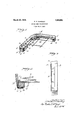
Figure 1 is a perspective View of my improved rim, showing part of a conventional grille base attached thereto.
Figure 2 is a sectional View of the run, enlarged, showing the upholstery material attached to the wooden insert of the rim, and a grille base with part of a spring thereon.
Figure 3 is a bottom plan of the rim strip, also enlarged.
In the drawings, A represents the rim as a whole, B is the grille base, C is a spring thereon and D, the upholstery material.
The rim A is made of a strip of metal, constituting the vertical wall 1, bent longitudinally back upon itself to form the vertical wall 2, of less height than the wall 1, then bent at right angles to form a horizontally disposed wall 3, a vertical wall 4, and a short bottom wall 5.
A filler, or insert of wood or other suitable material, indicated at 6, is securely held between the walls 2, 3, 4'and 5. The bottom 5 is pressed up againstthe' inse-rte, so as to slightly bite into the wood or other material.
The border wire 7 ofthegri-lle base 13 is supported-upon the top wall 3 and rests against the inner surface of the wall. 1, and, lSfCOIlIlBClEBCllZO the rim A by-spot Welding, indicated-at 8 on Figure 1.
The upholstery material 1) is brought downwardly over the front of the cushion and arranged-over the sniootli,-rounded edge 9 ofthe metal rim;A,and-theedge 10 of the material D, in-turned if desired, is securely tacked to the insert 6 by'taok 11. V
The construction shown and described is' @very simple but "various advantages result therefrom, which are of importance in the production of the spring cushion.
By attaching the grille base B to the metal rim A by spot welding, I am enabled to dispense with integral hooks, tongues or other fasteningsheretofore employed, and which it has been customary to stamp out from the metal of the rim and bend over the border Wire of the grille base.
The fiat top wall 3 and that portion of the wall 1 which extends above the wall 4, afford a firm support for the grille base B. The smooth front surface of the wall 1 extending considerably above the wall 4t presents a desirable backing for the upholstery material and prevents it from wearing out. The wall 1 extends sufficiently above the grille base B to hold the upholstery material away from the grille wire and. the body springs, which would otherwise rubagainst it and produce wear.
-This construction, wherein the wood insert rim is exposed at the bottom of the strip in-- stead of at the side, permits me to tack the upholstery material to the insert without the use of a trim strip or gimp.
I claim as my invention:
1. In a spring seat construction, a base frame comprising a metallic member bent longitudinally between its margins to form a vertically disposed outwardly facing wall and bent to form walls substantially U- shaped in cross section to provide a downwardly opening channel adjacent-the inner surface of said outwardly facing wall, said ported upon the upper wall of the channel vertical outer wall extending above the top wall of the channel, and a tacking strip within the channel.
2. In a spring seat construction, a base for body springs, a base frame therefor, comprising a metallic member bent longitudinally between its margins to form a smooth,
vertically disposed outwardly facing wall,
and bent to form walls substantially U shaped in cross section to provide a downwardly opening channel adjacent the inner surface of said outwardly facing wall, the vertically disposed outer wall extending above the top wall of the channel, and a tacking strip within the channel, said base for body springs being connected to'the base frame by spot'welding.
" 3. In a spring seat construction, a base member and abutting the inner surface of the vertical wall and held in position by spot welding.
4. A base frame for spring seat construction, comprising a strip of metal bent longitudinally between its side margins to form an upright front wall and bent back upon itself to form an integral channel member of inverted U-shape in cross section adjacent said upright wall, the height of the channel member being less than the height of the upright front wall, and a tacking strip within the channel.
5. A base framefor spring seat construc t'ion, comprising a strip of metal bent longitudinally between its side margins to form an upright front wall and bent back upon itself to form an integral channel member of inverted U-shape in cross section adjacent said upright wall, the height of the channel member being less than the height of the upright front wall, a tacking strip withinthechannel, and a retaining flange on one of the walls of the channel member.
In testimony that-I claim the foregoing as my invention I afiix my signature, this 3d day of May, 1927.
FRANK P. GHESLEY.
Priority Applications (1)
| Application Number | Priority Date | Filing Date | Title |
|---|---|---|---|
| US189960A US1663001A (en) | 1927-05-09 | 1927-05-09 | Spring seat construction |
Applications Claiming Priority (1)
| Application Number | Priority Date | Filing Date | Title |
|---|---|---|---|
| US189960A US1663001A (en) | 1927-05-09 | 1927-05-09 | Spring seat construction |
Publications (1)
| Publication Number | Publication Date |
|---|---|
| US1663001A true US1663001A (en) | 1928-03-20 |
Family
ID=22699482
Family Applications (1)
| Application Number | Title | Priority Date | Filing Date |
|---|---|---|---|
| US189960A Expired - Lifetime US1663001A (en) | 1927-05-09 | 1927-05-09 | Spring seat construction |
Country Status (1)
| Country | Link |
|---|---|
| US (1) | US1663001A (en) |
Cited By (2)
| Publication number | Priority date | Publication date | Assignee | Title |
|---|---|---|---|---|
| US2560688A (en) * | 1946-02-08 | 1951-07-17 | John M Dorton | Adjustable chair |
| US2909216A (en) * | 1957-09-03 | 1959-10-20 | Stubnitz Greene Spring Corp | Spring seat |
-
1927
- 1927-05-09 US US189960A patent/US1663001A/en not_active Expired - Lifetime
Cited By (2)
| Publication number | Priority date | Publication date | Assignee | Title |
|---|---|---|---|---|
| US2560688A (en) * | 1946-02-08 | 1951-07-17 | John M Dorton | Adjustable chair |
| US2909216A (en) * | 1957-09-03 | 1959-10-20 | Stubnitz Greene Spring Corp | Spring seat |
Similar Documents
| Publication | Publication Date | Title |
|---|---|---|
| US2186301A (en) | Upholstered seat back structure | |
| US1663001A (en) | Spring seat construction | |
| US2646840A (en) | Upholstered seat structure | |
| US2117748A (en) | Spring cushion structure | |
| US2637137A (en) | Upholstery | |
| US2572591A (en) | Metal chair | |
| US1840275A (en) | Chair back construction | |
| US1906233A (en) | Chair and supporting device | |
| US1719532A (en) | Chair | |
| US1756579A (en) | Base frame for spring-cushion seats | |
| US1700022A (en) | Folding chair | |
| US2125519A (en) | Seat spring cover anchor | |
| US1696937A (en) | Top construction | |
| US1454577A (en) | Attachment for seat covers | |
| US1785359A (en) | Spring structure | |
| US1147287A (en) | Chair-seat. | |
| US1230948A (en) | Sheet-metal seating. | |
| JPH0246797Y2 (en) | ||
| US2702221A (en) | Metal trim | |
| US1159477A (en) | Spring structure. | |
| US2175674A (en) | Container | |
| US1221976A (en) | Cushion structure. | |
| US196824A (en) | Improvement in chair seats and backs | |
| US2147611A (en) | Structural member for seat construction and the like | |
| US1480074A (en) | Spring seat |