US1662012A - Feeding mechanism for stamp presses - Google Patents
Feeding mechanism for stamp presses Download PDFInfo
- Publication number
- US1662012A US1662012A US93980A US9398026A US1662012A US 1662012 A US1662012 A US 1662012A US 93980 A US93980 A US 93980A US 9398026 A US9398026 A US 9398026A US 1662012 A US1662012 A US 1662012A
- Authority
- US
- United States
- Prior art keywords
- shelf
- sheet
- sheets
- shaft
- feed
- Prior art date
- Legal status (The legal status is an assumption and is not a legal conclusion. Google has not performed a legal analysis and makes no representation as to the accuracy of the status listed.)
- Expired - Lifetime
Links
- 230000007246 mechanism Effects 0.000 title description 104
- 239000002184 metal Substances 0.000 description 45
- 239000000314 lubricant Substances 0.000 description 11
- 241000282472 Canis lupus familiaris Species 0.000 description 4
- 238000010276 construction Methods 0.000 description 3
- 238000005034 decoration Methods 0.000 description 3
- 101100340610 Mus musculus Igdcc3 gene Proteins 0.000 description 2
- 238000007792 addition Methods 0.000 description 2
- 230000000694 effects Effects 0.000 description 2
- 239000000463 material Substances 0.000 description 2
- 230000003534 oscillatory effect Effects 0.000 description 2
- 239000011435 rock Substances 0.000 description 2
- 230000035882 stress Effects 0.000 description 2
- 238000006066 Comins reaction Methods 0.000 description 1
- 241000381592 Senegalia polyacantha Species 0.000 description 1
- ATJFFYVFTNAWJD-UHFFFAOYSA-N Tin Chemical compound [Sn] ATJFFYVFTNAWJD-UHFFFAOYSA-N 0.000 description 1
- 239000000853 adhesive Substances 0.000 description 1
- 230000001070 adhesive effect Effects 0.000 description 1
- 230000032683 aging Effects 0.000 description 1
- 238000005452 bending Methods 0.000 description 1
- 230000009286 beneficial effect Effects 0.000 description 1
- CBYWMRHUUVRIAF-UHFFFAOYSA-N diethylthiambutene Chemical compound C=1C=CSC=1C(=CC(C)N(CC)CC)C1=CC=CS1 CBYWMRHUUVRIAF-UHFFFAOYSA-N 0.000 description 1
- 238000006073 displacement reaction Methods 0.000 description 1
- 230000005484 gravity Effects 0.000 description 1
- 239000004922 lacquer Substances 0.000 description 1
- 230000001050 lubricating effect Effects 0.000 description 1
- 238000004519 manufacturing process Methods 0.000 description 1
- 229920000136 polysorbate Polymers 0.000 description 1
- 230000002250 progressing effect Effects 0.000 description 1
- 238000004080 punching Methods 0.000 description 1
- 239000000126 substance Substances 0.000 description 1
- 230000000153 supplemental effect Effects 0.000 description 1
Images

Classifications
-
- B—PERFORMING OPERATIONS; TRANSPORTING
- B21—MECHANICAL METAL-WORKING WITHOUT ESSENTIALLY REMOVING MATERIAL; PUNCHING METAL
- B21D—WORKING OR PROCESSING OF SHEET METAL OR METAL TUBES, RODS OR PROFILES WITHOUT ESSENTIALLY REMOVING MATERIAL; PUNCHING METAL
- B21D43/00—Feeding, positioning or storing devices combined with, or arranged in, or specially adapted for use in connection with, apparatus for working or processing sheet metal, metal tubes or metal profiles; Associations therewith of cutting devices
- B21D43/20—Storage arrangements; Piling or unpiling
- B21D43/24—Devices for removing sheets from a stack
Definitions
- My invention relates to feeding mechanisms for stamp presses, and more particularly to a mechanism adapted to feed sheet metal in relation to the punch or ram of 5 the press.
- feeding mechanisms for stamp presses have included therein a feed shelf adapted to receive a pile of metal sheets, and have associated therewith means whereby the lowermost sheet is removed from the pile and advanced with a step by step movement following the down ward strokes of the ram, the sheets being fed from the bottom of the pile one after another. While the actual feeding of the sheets by such mechanisms is automatic, nevertheless the number of sheets which can be mounted upon the feed shelf is limited by reason of the fact that the weight of a pile of sheets isso great that, even when the sheets in a pile are only some thirty or forty in number, when these sheets have a decorated surface there is likelihood of marring this surface even though each of the sheets as to the decorated surface be lubricated.
- one side of the sheet is decorated and the other side is coated with a lacquer to facilitate the bonding of a cushion disk within the made shell.
- a lacquer to facilitate the bonding of a cushion disk within the made shell.
- the presence of oil upon this laquered surface interferes with the proper bonding action of the adhesive used, so that extreme care is required in the use of the lubricant upon the decorated, and in some instances the plain, surface of the tin sheet.
- the presence of this lubricant is beneficial to the dies.
- the sheets in a feeding mechanism embodying my invention are removed from the top of a ile by means of certain old and well known ceding mechanisms and are intermittently advanced in relation to the punch press at intervals determined by the progress of a sheet along the feed shelf of said press, the deliver of the sheets one at a time to this shelf bemg controlled as a result of the movement of the sheet along the feed shelf and towards the ram, and the punches carried thereby.
- the mechanism for transporting the sheets from the pile from which they are removed is so constructed, and timed in its operation, that immediately following the delivery of a sheet thereby to the feed shelf of the press, a succeeding sheet will be brought into a position to be fed upon the shelf with a speed which will bring it in close juxtaposition to the sheet being acted upon by the punches so as to permit a continuous operation of the press without loss of strokes of the ram.
- I provide guide means which will accurately center each sheet with relation to the ram and the feed shelf, thus minimizing possibility of lateral displacement of the sheet in its travel from the pile to the feed shelf which might result in inaccuracy in the location of the decorations upon the sheet with relation to the punches.
- this accuracy in the positioning of the sheets is not so important, although it will permit extreme nicety in the laying out of the punches in relation to the sheet and avoid excessive wastage of the material of the sheet.
- the actuation of this guard is also controlled as a result of the progress of a sheet along the feed shelf and toward the punches.
- I preferably also provide means whereby a lubricating substance may, while the sheet is progressing from the pile to the feed shelf of the press, be applied to one surface thereof, that surface presented toward the feed shelf and the female dies, thus not only securing the advantage of the automatic application of the lubricant to the sheets, but avoiding contact of a lubricated face of one sheet, with a lacquered or plain face of another sheet.
- the invention consists primarily in the combination with the feed shelf of a stamp press, means whereby a metal sheet may be moved along said shelf, and means adapted to remove and advance one metal sheet at a time from the top of a ile of sheets, of a feeding mechanism including therein a support adapted to receive sheets moved from said pile, means for moving sheets along said support and delivering them to said feed shelf in operative relation to the means for moving them along said shelf, and means controlled by a late upon said shelf whereby said means or moving the sheets along said support is intermittently actuated; and in such other novel features of construction and combination of parts as are hereinafter set forth and described, and more particularly pointed out in the claims hereto appended.
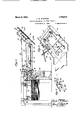
- Fig. 1 is a longitudinal section through a feeding mechanism embodying the invention, illustrating diagrammatically an old and well known mechanism by which sheets are removed one at a time from a pile and advanced toward the feed shelf, and also showing the feed shelf construction, but no other part of the stamp or punch press;
- Fig. 2 is a. plan view thereof
- Fig. 3 is a perspective view of a fragmentary portion of the feed shelf
- Fig. 4 is a detail view of the cam co-operating with the mechanism controlled by the metal sheet and causing the intermittent actuation of the various co-operating mechanisms in the machine;
- Fig. 5 is a detail view of the clutch mechanism through which such intermittent operation is imparted to the mechanism.
- a feed shelf 13 of an ordinary punch or stamp press To the right of Fig. 1 of the drawings. is shown a fragmentary portion of a feed shelf 13 of an ordinary punch or stamp press, the ordinary reci rocatory feeding racks 14 being shown, ut the actuating means therefor being omitted as such are old and well known in the art.
- the feed shelf 13 is provided with the usual side gauge bars 15 and front gauge bar 16, the latter being spaced above the feed shelf a sufficient distance to permit the free passa e of a sheet below same and along the she f into operative relation to the punches not shown, and the former having straightening guides 15.
- a sheet Arranged intermediate the rollers 10 and 11 and the shelf 13 are supports for a sheet consisting of parallel bars 17 of a length to permit a sheet to be brought with its forward edge closely adjacent the feed shelf.
- a bell crank lever 25 Pivotally mounted with relation to the feed shelf 13 is a bell crank lever 25, one arm 26 of which is downturned with its end projecting toward and adapted to pass through an opening 13 in the feed shelf 13, the said arm being provided with a notched web 26 for limiting the amount of movement of the arm towards the shelf 13.
- the other arm 27 of the bell crank lever 25 is connected by a link 28 with a crank 29 upon the shaft 30.
- This shaft is also provided with a second crank arm 31 carrying a roller co-operating with a cam 32 upon the shaft 12, as shown more particularly in Fig.
- the arms 27 and 29 have spaced openings therein as shown, and the end of the link 28 co-operating with the arm 27 also has similar openings therein, these openings being provided merely for the purpose of permitting adjustment to ensure a proper relative movement of the arm 26, the shaft 30 and other mechanisms in the machine controlled through said shaft 30 or through said arm 29, which last named mechanisms are not illustrated.
- the cam 32 with which the arm 31 cooperates has a long rise 32" thereon, a long fall 32', and a short rise 32 followed by a short fall 32.
- the feeding mechanism 14 and parts associated therewith when a sheet is once delivered to the shelf 13, will operate in the usual manner to advance a sheet along the inclined shelf 13 or to the right, Fig. 1, the conditions arising from the use of the feeding mechanism of my invention being such, however, that only one sheet at a time is delivered to, or is present upon the shelf 13, so that the sheet which is thus being advanced will be subjected to no material pressure from above.
- the guard 35 is alternately raised to a position above the bars 17, and out of engagement with the shelf 13, and permitted to descend into engagement with said shelf by means of an oscillatory lever 36 pivote at 37, one arm of this bar being connected to the guard 35 by means of the short link 38 pivoted to said guard and to the long arm of said lever.
- the other and shorter arm of said lever carries a roller engageable y a cam 39 carried by and rotatable with the shaft 12, the rise and fall of this cam being so will be raised immediatel itial movement of the s aft 12 with each intermittent feeding movement of the rollers 18, 20 and 22, and will be held in this elevated position until the entire sheet has passed from the supports 17 to upon the shelf 13, the guard 35 then being allowed to descend into engagement with the sheet upon the shelf 13 immediately to, or substantially simultaneously with, the initial feeding movement of the sheet by the racks 14.
- I provide a trough 40 having a wiper pad 40 extending transversely of the supporting bars 17 and having idly mounted therein a roller 41, the upper surface of which roller is on substantiall the following the inproportioned that the guard 35 prior plane of the supporting bars 17 an has a light frictional contact with the plate passing thereover.
- Power is applied to the machine from the motor 42 through a gear train acting upon a gear 43 idly mounted upon the shaft 12, this car being continuously rotated and carrying a plurality of spring-pressed dogs 44 adapted to engage a co-operating tooth 45 upon.
- a cam 47 Slidably mounted upon the main frame and adjacent said disk is a cam 47, the slide 48 of which has a slot therein engageable by a cam plate 49 carried by the shaft 30.
- the cam 47 is normally maintained in a position where it will be in engaging relation with the do 44 to hold them out of engagement with t ieir co-operating tooth 45, during a part of a continuous rotation of the gear 43, and permit the closing of the clutch formed by said dogs 44 and said tooth 45, with movement of the shaft 30 as determined by the movement of a sheet upon the shelf 13.
- the operation of the herein described mechanism is substantially as follows Assumin that a run of a stamp or punch press is to e started, and no metal sheet is upon the shelf 13 or supports 17, the spring 34 will have actuated the shaft 30, the downturned end 26 of the bell crank lever having entered the opening 13 to permit this movement of the shaft 33. The turning of the said shaft 30 will have actuated certain valves through the movement of the crank 29 to control the suction and air jet devices of the mechanism A when power is applied to the mechanism, so that a metal sheet will he raised from the pile 15 and moved into engaging relation with the feed rollers 10 and 11. This is the initial step in the feeding of the sheet.
- the actuation of the shaft 30 will also have actuated the cam 47, as a result of the movements of the cam plate 49, in a manner to move it out of engaging relation with the dogs 44, so that with the rotation of the gear 43, said dogs will be set in relation to the tooth 45 and thus, through the gear 43, cause the rotation of the shaft 12 and the cams 32 and 39 carried thereby, as well as the rotation of others, and the usual controlling devices carried by this shaft and operative in relation to the mechanism A.
- Such other controlling devices are not shown in the drawings, nor herein described as they are all old and well known in this art.
- the turning of the feed rollers 10 and 11 from the shaft 12 will cause a simultaneous turning of the sets of feed rollers 18 and 19, 20 and 21, 22 and 23 through the chain 24.
- the cam 39 will oscillate the lever 36, raising the end thereof with which the link 38 is connected, and through said link also raising the guard 35 to the position indicated in dotted lines, Fig. 1, with the free edge thereof above the meeting line of the rollers 22 and 23.
- the length of the rise upon this cam 39 will hold the guard 35 in this position for a sufficient interval to permit t e delivery of a sheet from the supports 17 to the shelf 13, although when starting a run, no such plate will be delivered with the first actuation of the guard.
- the fall 32 of the cam 32 will permit the shaft 30 to remain in the position above referred to, for a sufficient interval to ensure the delivery of a sheet to the rollers 10 and 11 by the mechanism A, the rise 32 becoming operative following the delivery of this sheet, and having the effect of oscillating the shaft 30 in a manner to raise the downturned end 26 of the lever 25 to permit the assage of a sheet between this lever and tide shelf 13.
- the following fall 32 imparts a short oscillatory movement to the lever 25 which will have a tendency to force the sheet at this point. against the shelf 13 if it has not already been hrought to this position by the guard 35, or through the inherent tendency of the forward edge of the sheet to fall upon the shelf.
- the rise 32 will again raise the downturned end 26 and hold it raised until a sheet has been fully positioned upon the shelf 13.
- the roller 11 is driven as are the feed rollers 18, the chain 24, however.
- the feeding movement of the sheets from the pile B to the sup orts 17, and from these supports to the she f 13, is a more rapid movement than the feeding movement of the sheets along the shelf 13, the entire movement of the sheet from the supports 17 to the shelf 13 occurring in a. fraction of the time re uired to feed a sheet fromthe shelf 13 to t 1e punches, in fact in about onesixth of the time.
- This higher speed of a sheet passing to the shelf in relatlon to the sheet passin therefrom to the punches permits succee ing sheets to be brought into close juxtaposition upon the shelf and thus ensures continuity in the punching operation upon a succession of sheets.
- This centering 1s highly desirable as permitting reat accuracy in the icing out of the punc es with relation to the cot from which objects are to be out, and will also ensure great accuracy in the positioning of the decorative ortion of a sheet in relation to such ,punc 16S.
- a sheet is thus delivered from a file to a supportbetween this pile and the eed shelf of a punch press, comin to rest closely adjacent the feed shelf ant i remainin in this position durin a dwell corresponding with a number of r ciprocations of the ram of a press and until a precedin sheet has been almost completely consume whereupon the automatical y actuated starting or controlling mechanism is actuated to start this sheet from its condition of rest and deliver it upon the feed shelf in close juxtaposition to the sheet previously fed upon this shelf.
- This intermittent action of the feedin mechanisms permits acontinued operation 0 the punch press and hence high output capacity.
- the guard 35 will hold the sheet perfectly flat in relation to the feed shelf 13 and the racks 14, andwill prevent any such buckling of the. sheet as might cause variation in the quantity of feeding movement thereof ad acent the punches.
- the supplemental fixed ards as heretofore stated prevent buc mg of the sheet during that interval when a fresh sheet is bein delivered to the shelf and the uard 35 is necessarily moved away from t e shelf to afford clearance for the oncoming sheet.
- the feeder may be applied to punch presses of a' design now commonly used and of course may be varied in its details to adapt it to different designs of presses.
- a feeding mechanism embodying therein the combination with the feed shelf of a stam press means whereby a metal sheet may moved along said shelf, and means adapted to remove and advance one metal sheet at a time from the top of a pile of sheets, of a support adapted to receive sheets moved from said pile, means for moving sheets along said support and delivering them to said feed shel 1n opprative relation to the means for moving 1; em along said shelf, and intermittently operative means controlled by a late upon said shelf whereby said means or moving the sheets along said support is successively made operative to deliver a sheet to said shelf, and inoperative for an interval to afford a dwell during which a sheet may be fed along said shelf.
- a feeding mechanism embodying therein the combination with the feed shelf of a stamp pres means whereby a metal sheet may be moved along said shelf, and means adapted to remove and advance one metal sheet at a time from the top of a pile/of sheets of a support adapted to receive sheets moved from said pile, means for moving sheets along said support and delivering them to said feed shel in operative relation to the means for moving them along said shelf, means controlled by a plate upon said shelf whereby said means for moving the sheets along said support is intermittently actuated, a ard movably supported in enfiing relation with a sheet upon said feed f, and means whereby said guard will be port is successive moved away from said shelf while said last named means are operative, and will be moved toward said shelf and in engaging relation with a sheet, when said last named means become inoperative.
- a feeding mechanism embodying therein the combination with the feed shelf of a stamp press means whereby a metal sheet may be moved along said shelf, and means adapted to remove and advance one metal sheet at a time from the top of a pile of sheets, of a support adapted to receive sheets moved from said pile, means for moving sheets along said support and delivering them to said feed shelf in operative relation to the means for movingthem along said shelf, intermittently operative means controlled by a plate upon said shelf whereby said means for movin the sheets along said supf made operative to deliver a sheet to said shelf, and inoperative for an interval to afford a dwell during which a sheet may be fed alongsaid shelf, and fixed guards operative upon a sheet upon said shelf.
- said feed shelf in operative relation to the means for moving them along said shelf, centering devices operative upon a sheet as it passes from said support to the shelf, and intermittently operative means controlled by a late upon said shelf whereby said meansor moving the sheets along said support is successively.
- Afeeding mechanism embodyin therein the combination with the feed sie'lf of a stamp press means whereby a metal sheet may be moved along said shelf, and means adapted to remove and advance one metal sheet at a time from the top of a pile of sheets, of'a support adapted to receive sheets moved from said pile, means for moving sheets alon said support and delivering them to sai feed shelf in Operative relation to the means for moving them along said shelf, a shaft a source of power, a clutch mechanism adapted to connect said shaft with said source of power, 0 rativc connections between said shaft an said means, a member movablymounted adjacent said feed shelf adapted to have a normal tendency to move toward said shelf or into engagement with a plate thereon, said shelf having an opening therethrough to receive said member, a second shaft, means carried by said shaft and operative upon said clutch mechanism, connections between said member and said shaft, a spring acting upon said shaft to normally move said member toward said feed shelf and simultaneously actuate said clutch mechanism whereby the actuation of said clutch
- clutch mechanism is controlled by the engagement of said member with a sheet upon said shelf, means whereby during the feeding movement of a sheet from said support to said shelf, said member is moved out of enga ing position with relation to said sheet an said shelf, and said clutch mechanism is made inoperative at the conclusion of said feeding movement, a guard movably supported in on aging relation with a sheet upon saidfeed s elf, an intermittently actuated cam, and a lever, one arm of which is acted upon by said cam and the other arm of which is connected with said guard whereby said guard will be moved away from said shelf while said last named means are operative, and will be moved toward said shelf and in engagin relation with a sheet, when said last name means become ino rative.
- a feeding mechanism em odyin therein the combination with the feed shelf of a stamp press means whereby a metal sheet may be moved along said shelf, and means adapted to remove and advance one metal sheet at a time from the top of a pile of sheets, of a support adapted to receive sjheets moved from said pile, means for moving sheets along said sup ort and delivering them to said feed she f in operative rela tion to the means for moving them along said shelf, means controlled by a tplate upon said shelf whereby said means or moving the sheets along said support is intermittently actuated, a guard movably supported in engaging relation 'a-sheetuponsaid f ed t, means whereby, a dguardewill be moved away shelfwhilesaid last named means are 'operfltiwi and willube moved toward said shelf and in engaging relation with a sheet, when said last named means become inoperative, and fixed guards operative upon a sheet upon said shelf.
- a feeding mechanism embodying therein the combination with the feed shelf of a stamp press means whereby a metal sheet ma be moved along said shelf, and means a apted to remove and advance one metal sheet at a time from the top of a pile of sheets, of a support adapted to receive sheets moved from said pile, means for moving sheets along said support and delivering them to said feed shelf in operative relation to the means for moving them along said shelf, a shaft, a source of power, a clutch mechanism adapted to connect said shaft with said source of power, operative connections betweensaid shaft and said means, a member movably mounted adjacent said feed shelf adapted to have a normal tendency to move toward said shelf or into engagement with a plate thereon, said shelf having an opening therethrough to receivesaid memher, a second shaft, means carried by said shaft and operative upon said clutch mechanism, connections between said membervand said shaft, a spring acting upon said shaft to normally move said member toward said feed shelf and simultaneously actuate said clutch mechanism whereby the actuation of said clutch mechanism is controlled by
- a feeding mechanism embodying therein the combination with the feed shelf of a stamp press means whereby a metal sheet may be moved along said shelf, and means adapted to remove and advance one metal sheet at a time from the top of a pile of sheets, of a support adapted to receive sheets moved from said pile, means for moving sheets along said support and delivering them to said feed shelf in operative relation to the means for moving them along said shelf, a shaft, a source of power, a clutch mechanism adapted to connect said shaft with said source of power, operative connections between said shaft and said means, a member movably mounted adjacent said feed shelf adapted to have a normal tendency to move toward said shelf or into engagement with a plate thereon, said shelf having an opening therethrough to receive said member, a second shaft, means carried by said shaft and operative upon said clutch mechanism, connections between said member and said shaft, a spring acting upon said shaft to normally move said member toward said feed shelf and simultaneously actuate said clutch mechanism whereby the actuation of said clutch mechanism is con trolled by the engagement of said member
- guard movably supported in engaging relation with a sheet upon said feed shelf, an intermittently actuated cam, a lever, one arm of which is acted upon by said cam and the other arm of which is connected with said guard, whereby said guard will be moved away from said shelf while said last named means are operative, and will be moved toward said shelf and in engagin relation with a sheet, when said last named means become inoperative, and centering devices operative upon a sheet as it passes from said sup ort to said shelf.
- a fee ing mechanism embodying therein the combination with. the feed shelf of a stamp press, means whereby a metal sheet may be moved along said shelf, and means adapted to remove and advance one metal sheet at a time from the top of a pile of sheets, of a""support adapted to receive sheets moved from said pile, means for moving sheets along said support and delivering them to said feed shelf in operative relation to the means for moving them along said shelf, intermittently operative means controlled by a plate upon said shelf whereby said means for moving the sheets along said support is successivel made operative to deliver a sheet to said shelf, and inoperative for an interval to afford a dwell during which a sheet ma be fed along said shelf, a trough below said.
- a feeding mechanism embodying therein in combination with the feed shelf of a stamp press including therein a front gauge spaced away from said shelf, and side auges, means whereby a metal sheet may e moved along said shelf and along said front gauge, and means adapted to remove and advance one metal sheet at a time from the top of a pile of sheets, of a support adapted to receive sheets moved from said pile, means for moving sheets along said su ort and delivering them to said feed she f in operative relation to the means for moving them alon said shelf, a shaft, a source of power, a cutch mechanism ada ted to connect said shaft with said source 0 power, operative connections between said shaft and said means, a member movably mounted adjacent said feed shelf adapted to have a normal tendency to move toward said shelf or into engagement with a plate thereon, said shelf having an opening therethrough to receive said member, a second shaft, means carried by said shaft and operative upon said clutch mechanism, connections between said member and said shaft, a spring acting upon said shaft to normally move
- a shaft a source of power, a clutch mechanism adapted to connect said shaft with said source of power, operative connections between said shaft and said means, a member movably mounted adjacent said feed shelf adapted to have a normal tendency to move toward said shelf or into engagement with a plate thereon, said shelf having an opening therethrmigh to receive said memher, a second shaft, means carried by said shaft and operative upon said clutch mechanism, connections between saidmember and said shaft, a spring acting upon said shaft to normally move said member toward said feed shelf and simultaneously actuate said clutch mechanism whereby the actuation of said clutch mechanism is controlled by the engagement of said member with a sheet upon said shelf, means whereby during the feeding movement of a sheet from said support to said shelf, said member is moved out of engaging position with relation to said sheet and said shelf, and said clutch mechanism is made inoperative at the conclusion of said feeding movement, a guard movably supported in engaging relation with a sheet upon said feed shelf, and means whereby said guard will be moved away from said shelf while said last named means are operative,
- said feed shelf an intermittently actuated cam, and a lever, one arm of which is acted upon by said cam and the other arm of which is connected with said guard, whereby said guard will be moved away from said shelf while said last named means are operative, and will be moved toward said shelf and in engaging relation with a sheet, when said last named means become inoperative.
- a shaft a source of power, a clutch mechanism adapted to connect said shaft with said source of power, operative connections between said shaft and said means, a member movably mounted adjacent said feed shelf adapted to have a normal tendency to move toward said shelf or into engagement with a plate thereon, said shelf having an opening therethronprh to receive said memher, a second shaft, means carried by said shaft and operative upon said clutch mechanism, connections between said member and said shaft, a spring acting upon said shaft to normally move said member toward said feed shelf and simultaneously actuate said clutch mechanism whereby the actuation of said clutch mechanism is controlled by the engagement of said member with a sheet upon said shelf, means whereby during the feeding movement of a sheet from said support to said shelf, said member is moved out of engaging position with relation to said sheet and said shelf, and said clutch mechanism is made inoperative at the conclusion of said feeding movement, a guard movably supported in engaging relation with a sheet upon said feed shelf, and means whereby said guard will be moved away from said shelfwhile said last named means are
Landscapes
- Engineering & Computer Science (AREA)
- Mechanical Engineering (AREA)
- Sheets, Magazines, And Separation Thereof (AREA)
Description
'March 6, 1928.
C. E. M MANUS FEEDING MECHANISM FOR STAMP PRESSES Filed March 11. 1926 2 Sheets-Sheet 1 0M. 5: MLW
ATTORNEZ March 6, 1928. 1,662,012
c. E. MCMANUS FEEDING MECHANISM FOR STAMP PRESSES Filed March ll. 1926 2 Sheets-5heet 2 waif/6M INVENTOR Patented Mar. 6, 1928.
UNITED STATES PATENT OFFICE.
CHARLES E. MGMANUS, OF NEW YOIZK, N. Y., ASSIGNOR TO GROWN CORK & SEAL COK- PANY, INQ, OF NEW YORK, N. Y., A CORPORATION 01 NEW YORK.
FEEDING MECHANISM FOR STAMP PRESSES.
Application filed March 11, 1926. Serial No. 93,980.
My invention relates to feeding mechanisms for stamp presses, and more particularly to a mechanism adapted to feed sheet metal in relation to the punch or ram of 5 the press.
Heretofore, feeding mechanisms for stamp presses have included therein a feed shelf adapted to receive a pile of metal sheets, and have associated therewith means whereby the lowermost sheet is removed from the pile and advanced with a step by step movement following the down ward strokes of the ram, the sheets being fed from the bottom of the pile one after another. While the actual feeding of the sheets by such mechanisms is automatic, nevertheless the number of sheets which can be mounted upon the feed shelf is limited by reason of the fact that the weight of a pile of sheets isso great that, even when the sheets in a pile are only some thirty or forty in number, when these sheets have a decorated surface there is likelihood of marring this surface even though each of the sheets as to the decorated surface be lubricated.
The necessity for the frequent addition of plates to the pile upon the feed shelf not anly requires frequent attention from a press man, but there are frequent stoppages of the press from failure to properly feed the sheets with relation to the punches. There is furthermore, an absence of precision and uniformity in the positioning of different sheets, causing imperfections in the product.
In some classes of work, as for example in the stamping up of the metal shells used in the production of bottle seals, one side of the sheet is decorated and the other side is coated with a lacquer to facilitate the bonding of a cushion disk within the made shell. The presence of oil upon this laquered surface interferes with the proper bonding action of the adhesive used, so that extreme care is required in the use of the lubricant upon the decorated, and in some instances the plain, surface of the tin sheet. In addi tion to facilitating a free sliding movement of the lowermost sheet of a pile, the presence of this lubricant is beneficial to the dies.
With the above conditions in mind, I have constructed and used a. feeding mech anism for stamp presses whereby metal sheets are delivered one at a time to the feed shelf of a punch or stam press and to the step by step feeding mec anism associated therewith, so that in its travel along the feed shelf, and in relation to the punches, the sheet will not be subject to pressure from a pile of sheets and will thus have great freedom of movement which will minimize likelihood of the marring of the decorations upon the sheet, and at the same time permit that accuracy in the movements of the sheet with relation to the punches, desirable for securing a uniform quality in the output of the press. This condition results from the fact that where the sheet meets with practically no resistance to its sliding movement, it has no tendency to buckle under the stresses of the thrusts imparting the step by step movement thereof, and hence there will be a full feeding movement of the sheet with each such thrust. This will ensure an accurate centering of the designs upon the sheet in relation to the punches, and avoid that off-center location of a design which is commonly encountered in round objects having a skirt.
The sheets in a feeding mechanism embodying my invention, are removed from the top of a ile by means of certain old and well known ceding mechanisms and are intermittently advanced in relation to the punch press at intervals determined by the progress of a sheet along the feed shelf of said press, the deliver of the sheets one at a time to this shelf bemg controlled as a result of the movement of the sheet along the feed shelf and towards the ram, and the punches carried thereby.
The mechanism for transporting the sheets from the pile from which they are removed, is so constructed, and timed in its operation, that immediately following the delivery of a sheet thereby to the feed shelf of the press, a succeeding sheet will be brought into a position to be fed upon the shelf with a speed which will bring it in close juxtaposition to the sheet being acted upon by the punches so as to permit a continuous operation of the press without loss of strokes of the ram.
In conjunction with the feed shelf and said mechanism, I provide guide means which will accurately center each sheet with relation to the ram and the feed shelf, thus minimizing possibility of lateral displacement of the sheet in its travel from the pile to the feed shelf which might result in inaccuracy in the location of the decorations upon the sheet with relation to the punches. Of course if there are no decorations, this accuracy in the positioning of the sheets is not so important, although it will permit extreme nicety in the laying out of the punches in relation to the sheet and avoid excessive wastage of the material of the sheet.
To avoid buckling of the sheet during the thrust thereon by the feed mechanism associated with the feed shelf, I provide a guard which will hold the sheet perfectly flat upon the shelf and particularly adjacent the rack which imparts the feeding movement thereto, means being provided whereby this guard will be automatically moved away from the feed shelf during that interval when a sheet is being delivered to the shelf and toward the shelf immediately following the delivery of a sheet thereto. The actuation of this guard is also controlled as a result of the progress of a sheet along the feed shelf and toward the punches.
I preferably also provide means whereby a lubricating substance may, while the sheet is progressing from the pile to the feed shelf of the press, be applied to one surface thereof, that surface presented toward the feed shelf and the female dies, thus not only securing the advantage of the automatic application of the lubricant to the sheets, but avoiding contact of a lubricated face of one sheet, with a lacquered or plain face of another sheet.
I have found that a feed mechanism embodying my invention, in addition to the advantages above referred to, permits the press to be operated substantially uninterruptedly, thus materially increasing its output capacity.
The invention consists primarily in the combination with the feed shelf of a stamp press, means whereby a metal sheet may be moved along said shelf, and means adapted to remove and advance one metal sheet at a time from the top of a ile of sheets, of a feeding mechanism including therein a support adapted to receive sheets moved from said pile, means for moving sheets along said support and delivering them to said feed shelf in operative relation to the means for moving them along said shelf, and means controlled by a late upon said shelf whereby said means or moving the sheets along said support is intermittently actuated; and in such other novel features of construction and combination of parts as are hereinafter set forth and described, and more particularly pointed out in the claims hereto appended.
Referring to the drawings,
Fig. 1 is a longitudinal section through a feeding mechanism embodying the invention, illustrating diagrammatically an old and well known mechanism by which sheets are removed one at a time from a pile and advanced toward the feed shelf, and also showing the feed shelf construction, but no other part of the stamp or punch press;
Fig. 2 is a. plan view thereof;
Fig. 3 is a perspective view of a fragmentary portion of the feed shelf;
Fig. 4 is a detail view of the cam co-operating with the mechanism controlled by the metal sheet and causing the intermittent actuation of the various co-operating mechanisms in the machine; and
Fig. 5 is a detail view of the clutch mechanism through which such intermittent operation is imparted to the mechanism.
Like numerals refer to like parts throughout the several views.
In the embodiment of the invention shown in the drawings, it is illustrated in connection with an old and well known suction actuated feeding mechanism shown at the left of Fig. 1 and indicated by the reference letter A, this mechanism being adapted to lift one metal sheet at a time from the pile B and transport it to the right of Fig. l a sufficient distance to permit its engagement by the feed rollers 10 and 11. This mechanism in its entirety, well as the means for controlling the suction and the air jets utilized in lifting and removin the sheet, are all old and well known in this and other arts, and a detailed description thereof is unnecessary. Suffice it to say, that all of the controls for the mechanism A are carried by a shaft 12 excepting the main control, which is novel to my herein described mechanism, the operative effect of which is determined by the position of the plate upon the feed shelf of a punch or stamp press.
To the right of Fig. 1 of the drawings. is shown a fragmentary portion of a feed shelf 13 of an ordinary punch or stamp press, the ordinary reci rocatory feeding racks 14 being shown, ut the actuating means therefor being omitted as such are old and well known in the art. The feed shelf 13 is provided with the usual side gauge bars 15 and front gauge bar 16, the latter being spaced above the feed shelf a sufficient distance to permit the free passa e of a sheet below same and along the she f into operative relation to the punches not shown, and the former having straightening guides 15.
Arranged intermediate the rollers 10 and 11 and the shelf 13 are supports for a sheet consisting of parallel bars 17 of a length to permit a sheet to be brought with its forward edge closely adjacent the feed shelf.
Operating upon the sheet between said bars 17 are three sets of feed rollers 18 and 19, 20 and 21, 22 and 23, the upper rollers 19, 21 and 23 of each set being mounted ad acent a suitable frame, spring-pressed toward the co-operating lower roller 18, 20 and 22 of each set respectively. The lower rollers 18, 20 and 22 are all positively driven by means of the chain indicated at 24. The rollers 20 and 21, and 22 and 23 are so spaced as to simultaneously engage a sheet adjacent the rear and forward edges thereof, which engagement will occur not only during the travel of a sheet, but when it is at rest upon the bars 17 preparatory to the next actuation of the feeding mechanism, which will ensure its delivery to the feed shelf 13.
Pivotally mounted with relation to the feed shelf 13 is a bell crank lever 25, one arm 26 of which is downturned with its end projecting toward and adapted to pass through an opening 13 in the feed shelf 13, the said arm being provided with a notched web 26 for limiting the amount of movement of the arm towards the shelf 13. The other arm 27 of the bell crank lever 25 is connected by a link 28 with a crank 29 upon the shaft 30. This shaft is also provided with a second crank arm 31 carrying a roller co-operating with a cam 32 upon the shaft 12, as shown more particularly in Fig. 4 of the drawings, and with a third arm upon by a spring 34 having a normal tendency to impart a thrust to the link 28 in a direction forcing the downturned end of the arm 26 toward the shelf 13, and into engagement with a metal sheet if it be upon said shelf and interposed between the arm 26 and the opening 13.
The arms 27 and 29 have spaced openings therein as shown, and the end of the link 28 co-operating with the arm 27 also has similar openings therein, these openings being provided merely for the purpose of permitting adjustment to ensure a proper relative movement of the arm 26, the shaft 30 and other mechanisms in the machine controlled through said shaft 30 or through said arm 29, which last named mechanisms are not illustrated.
The cam 32 with which the arm 31 cooperates has a long rise 32" thereon, a long fall 32', and a short rise 32 followed by a short fall 32. a
The feeding mechanism 14 and parts associated therewith, when a sheet is once delivered to the shelf 13, will operate in the usual manner to advance a sheet along the inclined shelf 13 or to the right, Fig. 1, the conditions arising from the use of the feeding mechanism of my invention being such, however, that only one sheet at a time is delivered to, or is present upon the shelf 13, so that the sheet which is thus being advanced will be subjected to no material pressure from above.
The sheets, however, possess considerable weight, and are of comparatively thin gauge, so that the thrust exerted thereupon by the 33 acted b racks 14, two such racks being ordinarily used, will have a tendency to buckle the sheet to an extent which will seriously interfere with its movement in relation to the punches, were no means provided sufficient to overcome this tendency to buckle, and thus hold the sheets flat in relation to said shelf 13. To prevent this buckling of the sheets, I pivotally mount a guard 35 upon the front gauge 16, or in any other suitable position, which guard has parallel side bars above and in alinement with the reciprocatory racks 14. This guard 35 descends by gravity toward the shelf 13, and has sufficient weight and rigidity to withstand the stresses arising from the tendency of the metal sheet to buckle.
The guard 35 is alternately raised to a position above the bars 17, and out of engagement with the shelf 13, and permitted to descend into engagement with said shelf by means of an oscillatory lever 36 pivote at 37, one arm of this bar being connected to the guard 35 by means of the short link 38 pivoted to said guard and to the long arm of said lever. The other and shorter arm of said lever, carries a roller engageable y a cam 39 carried by and rotatable with the shaft 12, the rise and fall of this cam being so will be raised immediatel itial movement of the s aft 12 with each intermittent feeding movement of the rollers 18, 20 and 22, and will be held in this elevated position until the entire sheet has passed from the supports 17 to upon the shelf 13, the guard 35 then being allowed to descend into engagement with the sheet upon the shelf 13 immediately to, or substantially simultaneously with, the initial feeding movement of the sheet by the racks 14.
To apply a suitable lubricant to that face of each sheet which is presented toward the shelf 13 as it is delivered thereto, and also toward the female dies upon the bolster of the press, I provide a trough 40 having a wiper pad 40 extending transversely of the supporting bars 17 and having idly mounted therein a roller 41, the upper surface of which roller is on substantiall the following the inproportioned that the guard 35 prior plane of the supporting bars 17 an has a light frictional contact with the plate passing thereover.
Power is applied to the machine from the motor 42 through a gear train acting upon a gear 43 idly mounted upon the shaft 12, this car being continuously rotated and carrying a plurality of spring-pressed dogs 44 adapted to engage a co-operating tooth 45 upon. a disk 46 upon the s left 12. Slidably mounted upon the main frame and adjacent said disk is a cam 47, the slide 48 of which has a slot therein engageable by a cam plate 49 carried by the shaft 30. The cam 47 is normally maintained in a position where it will be in engaging relation with the do 44 to hold them out of engagement with t ieir co-operating tooth 45, during a part of a continuous rotation of the gear 43, and permit the closing of the clutch formed by said dogs 44 and said tooth 45, with movement of the shaft 30 as determined by the movement of a sheet upon the shelf 13.
To avoid possible buckling of the sheet while the guard 35 is in its elevated position, I provide the front gauge 16 with a plurality of suitably spaced fixed guards 50 so spaced with relation to the shelf 13 as to prevent any possible buckling of the sheet during the final feeding movements thereof.
The operation of the herein described mechanism is substantially as follows Assumin that a run of a stamp or punch press is to e started, and no metal sheet is upon the shelf 13 or supports 17, the spring 34 will have actuated the shaft 30, the downturned end 26 of the bell crank lever having entered the opening 13 to permit this movement of the shaft 33. The turning of the said shaft 30 will have actuated certain valves through the movement of the crank 29 to control the suction and air jet devices of the mechanism A when power is applied to the mechanism, so that a metal sheet will he raised from the pile 15 and moved into engaging relation with the feed rollers 10 and 11. This is the initial step in the feeding of the sheet. The actuation of the shaft 30 will also have actuated the cam 47, as a result of the movements of the cam plate 49, in a manner to move it out of engaging relation with the dogs 44, so that with the rotation of the gear 43, said dogs will be set in relation to the tooth 45 and thus, through the gear 43, cause the rotation of the shaft 12 and the cams 32 and 39 carried thereby, as well as the rotation of others, and the usual controlling devices carried by this shaft and operative in relation to the mechanism A. Such other controlling devices are not shown in the drawings, nor herein described as they are all old and well known in this art. The turning of the feed rollers 10 and 11 from the shaft 12 will cause a simultaneous turning of the sets of feed rollers 18 and 19, 20 and 21, 22 and 23 through the chain 24.
\Vith the initial turning movement of the shaft 12, the cam 39 will oscillate the lever 36, raising the end thereof with which the link 38 is connected, and through said link also raising the guard 35 to the position indicated in dotted lines, Fig. 1, with the free edge thereof above the meeting line of the rollers 22 and 23. The length of the rise upon this cam 39 will hold the guard 35 in this position for a sufficient interval to permit t e delivery of a sheet from the supports 17 to the shelf 13, although when starting a run, no such plate will be delivered with the first actuation of the guard. The fall 32 of the cam 32 will permit the shaft 30 to remain in the position above referred to, for a sufficient interval to ensure the delivery of a sheet to the rollers 10 and 11 by the mechanism A, the rise 32 becoming operative following the delivery of this sheet, and having the effect of oscillating the shaft 30 in a manner to raise the downturned end 26 of the lever 25 to permit the assage of a sheet between this lever and tide shelf 13. The following fall 32 imparts a short oscillatory movement to the lever 25 which will have a tendency to force the sheet at this point. against the shelf 13 if it has not already been hrought to this position by the guard 35, or through the inherent tendency of the forward edge of the sheet to fall upon the shelf. The rise 32 will again raise the downturned end 26 and hold it raised until a sheet has been fully positioned upon the shelf 13.
\Vhen the roller upon the arm 31 passes from its engagement with the rise 32, the spring 34 will rock said shaft, and through the crank 29, link 28 and arm 27 of the bell crank lever 25, impart a downward thrust to the downturned end 26 of said lever 25, which will, in the event that a sheet has been delivered to the shelf 13, engage this sheet and thus check further rotation of the shaft 30. \Vhen starting a run, no sheet having been delivered to said shelf, the end 26 will pass through the opening 13 and thus actuate said shaft 30 in a manner to cause a repetition of the operations above referred Prior to the disengagement of the rise 32 with the arm 31, the rise of the cam 39 will have passed out of engaging relation with the short arm of the lever 36, thus permittin the guard 35 to descend toward the shelf 13, the cam 39 being brought to a position where, with the initial subsequent rotation of the shaft 12, said guard will be again raised.
The roller 11 is driven as are the feed rollers 18, the chain 24, however.
During this first cycle of operations, a sheet will be removed from the pile B and delivered to the rollers 10 and 11 by the mechanism A. the continued rotation of the shaft 12, will advance this sheet so as to cause it to be successively engaged by the rollers 18 and 19, and 20 and 21, but just prior to its engagement by the rollers 22 and 23, the rotation of the shaft 12 will be discontinued as a result of the clutch mechanism connecting same with the gear train 43 being made inoperative. This is the condition and relation of parts as shown in Fig. 1, with the from the shaft 12, 20 and 22 through Said rollers 10 and 11 with rated sheet is used.
exception that in this figure a sheet is shown upon the shelf 13.
With the following repetition of the above operations, with the initial movement of thcshaft 12. the rollers 20 and 21 will advance the sheet so. as to cause it to be engaged by the rollers 22 and 23, this occurring immediately following the raising of the guard 35. Hence during the next complete rotation of the shaft 12, a sheet will be forced from the supports 17 and delivered upon the shelf 13, substantially simultaneous] with the deliverv of a succeeding sheet I'Olll the pile B to the supports 17 and its advance along said supports.
The forward edge of the sheet, as it is delivered to theshelf .13, will pass beneath the fixed uards 50 which will prevent buckling of t l6 sheet during the final step by step feeding movements thereof by the racks 14, which feeding movements will occur while the guard is in its elevated position and a succeeding sheet is passing upon the shelf 13.
The feeding movement of the sheets from the pile B to the sup orts 17, and from these supports to the she f 13, is a more rapid movement than the feeding movement of the sheets along the shelf 13, the entire movement of the sheet from the supports 17 to the shelf 13 occurring in a. fraction of the time re uired to feed a sheet fromthe shelf 13 to t 1e punches, in fact in about onesixth of the time. This higher speed of a sheet passing to the shelf in relatlon to the sheet passin therefrom to the punches, permits succee ing sheets to be brought into close juxtaposition upon the shelf and thus ensures continuity in the punching operation upon a succession of sheets.
As a sheet is fed along the shelf 13, during a greater portion of this feeding movement, it will be inte osed between the clownturned end 26 of t e lever 25 and the opening 13 through said shelf. Duringthis time all parts of the feeding mechanism will be inoperative excepting the driving mechanism which rotates continuously. Immcdiately that the rear ed e of a sheet, however, passes from beneat the end '26, the spring 34 will rock the lever 25 and this set in motion the various mechanisms. In this manner the control of the feeding mechanism is determined by the feeding movement of the sheet upon the shelf 13 throu h a controlling mechanism including therem the lever 25 or its equivalent.
hen the trough 40 and roller 41 are used, as each sheet passes along the supports 17 it will engage this roller w ich is turned by the chain 24, the turning movement re sulting in the application of a lubricant from the trough 40 to the under or lithographed surface of the sheet when a deco- The flared ides 15 will correct any slight lateral 1 lacement of the sheets occurring during t air travel along the su ports 17 and accurately center the sheets in relation to the ram or unch and to the shelf 13. This centering 1s highly desirable as permitting reat accuracy in the icing out of the punc es with relation to the cot from which objects are to be out, and will also ensure great accuracy in the positioning of the decorative ortion of a sheet in relation to such ,punc 16S.
By means of a feeding mechanism constructed and operating as herein described a sheet is thus delivered from a file to a supportbetween this pile and the eed shelf of a punch press, comin to rest closely adjacent the feed shelf ant i remainin in this position durin a dwell corresponding with a number of r ciprocations of the ram of a press and until a precedin sheet has been almost completely consume whereupon the automatical y actuated starting or controlling mechanism is actuated to start this sheet from its condition of rest and deliver it upon the feed shelf in close juxtaposition to the sheet previously fed upon this shelf. This intermittent action of the feedin mechanisms permits acontinued operation 0 the punch press and hence high output capacity. The guard 35 will hold the sheet perfectly flat in relation to the feed shelf 13 and the racks 14, andwill prevent any such buckling of the. sheet as might cause variation in the quantity of feeding movement thereof ad acent the punches. The supplemental fixed ards as heretofore stated prevent buc mg of the sheet during that interval when a fresh sheet is bein delivered to the shelf and the uard 35 is necessarily moved away from t e shelf to afford clearance for the oncoming sheet.
The mechanism by which a sheet is held out of engagement with the racks 14 and by which the rear edge of the sheet is downturned suificiently to engage these racks, andthe sheet lowered into engag ment with the racks, is not shown in detai as such is old and well known and is merely a characteristic of the type of feed in connection with which my invention is shown.
All of these mechanisms rovided for use with the shelf 13 when a pi e of sheets is delivered thereto, are of course dispensed with as being unnecessary.
In a feeding mechanism the invention, it is to be noted that e ubricated face of one sheet never contacts with the lacquered face of another sheet. It will also be noted that no limitation is placed upon the height of the pile B of sheets, 80 that a very largs number of these sheets may be included in t e pile and thus permlt a continued run of the machine without requiring the attention of a feeder. In fact one man III may care for a large number of presses equipped with feeding mechanisms embodying my invention.
The possibility of feeding mishaps requiring frequent shutdowns of the press are reduced to a minimum, and are limited to an infrequent failure to properly feed a sheet due to the bending of the forward edge of the sheet to an extent to prevent its passage below the front gauge 16. The foregoing statements are based upon actual experience in the use of a feeder, and even these infrequent stoppages may be avoided by slight changes in the design of the mechamsm.
The feeder may be applied to punch presses of a' design now commonly used and of course may be varied in its details to adapt it to different designs of presses.
It is not my intention to limit the invention to the precise details of construction shown in the drawings, it being apparent that such may be varied without departing from the spirit and scope of the invention, and while still preserving the essential characteristics thereof.
Having described the invention, what I claim as new and desire to have protected by Letters Patent, is
1. A feeding mechanism embodying therein the combination with the feed shelf of a stam press, means whereby a metal sheet may moved along said shelf, and means adapted to remove and advance one metal sheet at a time from the top of a pile of sheets, of a support adapted to receive sheets moved from said pile, means for moving sheets along said support and delivering them to said feed shel 1n opprative relation to the means for moving 1; em along said shelf, and intermittently operative means controlled by a late upon said shelf whereby said means or moving the sheets along said support is successively made operative to deliver a sheet to said shelf, and inoperative for an interval to afford a dwell during which a sheet may be fed along said shelf.
2. A feeding mechanism embodying therein the combination with the feed shelf of a stamp pres, means whereby a metal sheet may be moved along said shelf, and means adapted to remove and advance one metal sheet at a time from the top of a pile/of sheets of a support adapted to receive sheets moved from said pile, means for moving sheets along said support and delivering them to said feed shel in operative relation to the means for moving them along said shelf, means controlled by a plate upon said shelf whereby said means for moving the sheets along said support is intermittently actuated, a ard movably supported in enfiing relation with a sheet upon said feed f, and means whereby said guard will be port is successive moved away from said shelf while said last named means are operative, and will be moved toward said shelf and in engaging relation with a sheet, when said last named means become inoperative.
3. A feeding mechanism embodying therein the combination with the feed shelf of a stamp press, means whereby a metal sheet may be moved along said shelf, and means adapted to remove and advance one metal sheet at a time from the top of a pile of sheets, of a support adapted to receive sheets moved from said pile, means for moving sheets along said support and delivering them to said feed shelf in operative relation to the means for movingthem along said shelf, intermittently operative means controlled by a plate upon said shelf whereby said means for movin the sheets along said supf made operative to deliver a sheet to said shelf, and inoperative for an interval to afford a dwell during which a sheet may be fed alongsaid shelf, and fixed guards operative upon a sheet upon said shelf.
4. A feeding mechanism embodying therein the combination with the feed shelf of a stam press, means whereb a metal sheet may e moved along said s elf, and means adapted to remove and advance one metal sheet at a time from the top of a pile of sheets, of a support adapted to receive sheets moved from said pile, means for moving sheets alon said support and delivering them to sai feed shelf in operative relation to the means for moving them along said shelf, intermittently operative means controlled by a plate upon said shelf whereby said means for moving the sheets along said support is successively made operative to deliver a sheet to said shelf, and inoperative for an interval to afford, a dwell durin which a sheet may be fed along said shel and means applying a lubricant to one face of a sheet while it is having movement along said sup ort.
5. A ceding mechanism embodying therein the combination with the feed shelf of a stam press, means whereby a metal sheet may be moved along said shelf, and means adapted to remove and advance one metal sheet at a time from the top of a pile of sheets, of a support adapted to receive sheets moved from said pile, means for moving sheets along said support and delivering them. to said feed shelf in operative relation to the means for moving them along said shelf, centering devices operative upon a sheet as it passes from said support to the shelf, and intermittently operative means controlled by a late upon said shelf whereby said meansor moving the sheets along said support is successively. made. operative to deliver a sheet to said shelf, and inoperative for an interval to afl'ord a dwell durmay e moved along said shelf, and means adapted to remove and advance one metal sheet at a time from the top of a pile of sheets, of a support adapted to receive sheets moved from said pile, means for moving sheets along said support and delivering them to said feed shelf in operative relation to the means for moving them along said shelf, a shaft, a source of power, a clutch mechanism adapted to connect said shaft with said source of power, operative connections between said shaft and said means, a member movatlzlj' mounted adjacent said feed shelf adap to have a normal tendency to move toward said shelf or into engagement with a plate thereon, said shelf having an opening therethrough to receive said member, and connections between said member and said clutch mechanism, whereby said clutch mechanism is controlled by the position of a sheet upon said feed shelf in relat ion to said memher to successively make said means for movm sheets along said sup rt operative to v dc iver a sheet to said she] and inoperative for an interval to afford a dwell during which a sheet may be fed alongosaid shelf.
'7. A feeding mechanism em dying therein the combination with the feed shelf of a stem press, means wherebya metal sheet may moved along said shelf, and means adapted to remove and advance one metal sheet at a time from the top of a pile of sheets, of a support adapted to'receive sheets moved from said pile, means for moving sheets along said support and delivering them to said feed shelf in o erative relation to the means for moving t em along said shelf, a shaft, a source of power, a clutch mechanism adapted to connect said shaft with said source of power, operative connections be tween said shaft and said means, a member movably mounted adjacent said feed shelf adapted to have a normal tendency to move toward said shelf or into engagement with a plate thereon, said shelf having an opening therethrough to receive said member, a'second shaft, means carried by said shaft and I operative upon said clutch mechanism, connections between said member and said shaft, :1 spring acting upon said shaft to normally move said member toward said feed shelf and simultaneously actuate said clutch mechanism whereby the actuation of said clutch mechanism is controlled by the engagement of said member with a sheet upon said shelf, and means whereby during the feeding movement of a sheet from said support to said shelf, said member is moved out of engaging position with relation to said sheet and said shelf, and said clutchmechanism is made inoperative at the conclusion of said feeding movement.
8. Afeeding mechanism embodyin therein the combination with the feed sie'lf of a stamp press, means whereby a metal sheet may be moved along said shelf, and means adapted to remove and advance one metal sheet at a time from the top of a pile of sheets, of'a support adapted to receive sheets moved from said pile, means for moving sheets alon said support and delivering them to sai feed shelf in Operative relation to the means for moving them along said shelf, a shaft a source of power, a clutch mechanism adapted to connect said shaft with said source of power, 0 rativc connections between said shaft an said means, a member movablymounted adjacent said feed shelf adapted to have a normal tendency to move toward said shelf or into engagement with a plate thereon, said shelf having an opening therethrough to receive said member, a second shaft, means carried by said shaft and operative upon said clutch mechanism, connections between said member and said shaft, a spring acting upon said shaft to normally move said member toward said feed shelf and simultaneously actuate said clutch mechanism whereby the actuation of said clutch mechanism is controlled by the engagement of said member with a sheet upon said shelf, a cam u on said first named shaft, and means carrie by said other shaft co-operating therewith, whereby during the feeding movement of a sheet from said support to said: shelf, said member is moved out of engaging position with relation to said sheet and said shelf, and said clutch in the combination with the feed shelf of a stamp press, means whereb a metal sheet may be moved along said s ielf, and means adapted to remove and advance one metal sheet at a time from the top of a pile of sheets of asupport adapted to receive sheets moved from said pile, means for moving sheets alon said support and delivering them to sai feed shelf in operative relation to the means for moving them along said shelf, means controlled by a late upon said shelf whereby said means or moving the sheets along said support is intermittently actuated,.a guard movably supported in engaging relatlon with a sheet upon said feed shelf, an intermittently actuated cam, and a lever, one arm of which is acted upon by said cam and the other arm of which is connected with said guard, whcreb said guard will be moved away from said shelf while said last named means are operative, and will be moved toward said shelf and in last named means become inoperativethem to said feed shelf in o erative relation shel to the means for moving tiem along said shelf, a shaft, :1 source of power, a clutch mechanism adapted to connect said shaft with said source of power, operative conections between said shaft and said means, =-a member movably mounted adjacent said feed shelf adapted to have a normal tendency to move toward said shelf or into engagement with a plate thereon, said shelf having an opening therethrough to receive said member, a second shaft, means carried by said shaft and operative upon said clutch mechanism connections between said member and said shaft, a spring acting upon said shaft to normally move said member toward said feed shelf and simultaneously actuate said clutch mechanism whereby the actuation of said. clutch mechanism is controlled by the engagement of said member with a sheet upon said shelf, means whereby during the feeding movement of a sheet from said support to said shelf, said member is moved out of enga ing position with relation to said sheet an said shelf, and said clutch mechanism is made inoperative at the conclusion of said feeding movement, a guard movably supported in on aging relation with a sheet upon saidfeed s elf, an intermittently actuated cam, and a lever, one arm of which is acted upon by said cam and the other arm of which is connected with said guard whereby said guard will be moved away from said shelf while said last named means are operative, and will be moved toward said shelf and in engagin relation with a sheet, when said last name means become ino rative.
11. A feeding mechanism em odyin therein the combination with the feed shelf of a stamp press, means whereby a metal sheet may be moved along said shelf, and means adapted to remove and advance one metal sheet at a time from the top of a pile of sheets, of a support adapted to receive sjheets moved from said pile, means for moving sheets along said sup ort and delivering them to said feed she f in operative rela tion to the means for moving them along said shelf, means controlled by a tplate upon said shelf whereby said means or moving the sheets along said support is intermittently actuated, a guard movably supported in engaging relation 'a-sheetuponsaid f ed t, means whereby, a dguardewill be moved away shelfwhilesaid last named means are 'operfltiwi and willube moved toward said shelf and in engaging relation with a sheet, when said last named means become inoperative, and fixed guards operative upon a sheet upon said shelf.
12. A feeding mechanism embodying therein the combination with the feed shelf of a stamp press, means whereby a metal sheet ma be moved along said shelf, and means a apted to remove and advance one metal sheet at a time from the top of a pile of sheets, of a support adapted to receive sheets moved from said pile, means for moving sheets along said support and delivering them to said feed shelf in operative relation to the means for moving them along said shelf, a shaft, a source of power, a clutch mechanism adapted to connect said shaft with said source of power, operative connections betweensaid shaft and said means, a member movably mounted adjacent said feed shelf adapted to have a normal tendency to move toward said shelf or into engagement with a plate thereon, said shelf having an opening therethrough to receivesaid memher, a second shaft, means carried by said shaft and operative upon said clutch mechanism, connections between said membervand said shaft, a spring acting upon said shaft to normally move said member toward said feed shelf and simultaneously actuate said clutch mechanism whereby the actuation of said clutch mechanism is controlled by the engagement of said member with a sheet upon said shelf, means whereby during the feeding movement of a sheet from said support to said shelf, said member is moved out of engaging position with relation to said sheet and said shelf, and said clutch mechanismis'made inoperative at the conclusion of said feeding movement, a guard movably supported in en a -ng relation with a sheet upon said feed 515i, an intermittently actuated cam, a lever, one arm of which'is acted upon by said cam and the other arm of which 18 connected with said guard, whereb said guard will be moved away from sai shelf g while said last named means are operative,
and will bemoved toward said shelf and in engagingrelation with a sheet, when said a last named means become inoperative, and
means ap lying a lubricant to-one face of a sheet whl e support. I
trolled by a plate upon said shelf whereby said means for moving the sheets along said support is successively made operative to deliver a sheet to said shelf, and inoperative for an interval to afford a dwell during which a sheet may be fed along said shelf, a trough below said support adapted'to receive a lubricant, and a roller mounted in said trough and projecting into engagement with a sheet upon said support whereby a lubricant is applied to one face of a sheet while it is having movement along said support.
14. A feeding mechanism embodying therein the combination with the feed shelf of a stamp press, means whereby a metal sheet may be moved along said shelf, and means adapted to remove and advance one metal sheet at a time from the top of a pile of sheets, of a support adapted to receive sheets moved from said pile, means for moving sheets along said support and delivering them to said feed shelf in operative relation to the means for moving them along said shelf, a shaft, a source of power, a clutch mechanism adapted to connect said shaft with said source of power, operative connections between said shaft and said means, a member movably mounted adjacent said feed shelf adapted to have a normal tendency to move toward said shelf or into engagement with a plate thereon, said shelf having an opening therethrough to receive said member, a second shaft, means carried by said shaft and operative upon said clutch mechanism, connections between said member and said shaft, a spring acting upon said shaft to normally move said member toward said feed shelf and simultaneously actuate said clutch mechanism whereby the actuation of said clutch mechanism is con trolled by the engagement of said member with a sheet upon said shelf, means whereby during the feeding movement of a sheet from said support to said shelf, said member is moved out of engaging position with relation to said sheet and said shelf, and said clutch mechanism is made inoperative at the conclusion of said feeding movement, a
guard movably supported in engaging relation with a sheet upon said feed shelf, an intermittently actuated cam, a lever, one arm of which is acted upon by said cam and the other arm of which is connected with said guard, whereby said guard will be moved away from said shelf while said last named means are operative, and will be moved toward said shelf and in engagin relation with a sheet, when said last named means become inoperative, and centering devices operative upon a sheet as it passes from said sup ort to said shelf.
15. A fee ing mechanism embodying therein the combination with. the feed shelf of a stamp press, means whereby a metal sheet may be moved along said shelf, and means adapted to remove and advance one metal sheet at a time from the top of a pile of sheets, of a""support adapted to receive sheets moved from said pile, means for moving sheets along said support and delivering them to said feed shelf in operative relation to the means for moving them along said shelf, intermittently operative means controlled by a plate upon said shelf whereby said means for moving the sheets along said support is successivel made operative to deliver a sheet to said shelf, and inoperative for an interval to afford a dwell during which a sheet ma be fed along said shelf, a trough below said. support ada ted to receive a lubricant, a roller mounte in said troughand projecting into engagement with a sheet upon saidsupport whereby a lubricant is applied to. one face of a sheet while it is having movement along said support, and centering devices operative upon a sheet as it passes from said support to said shelf.
16. A feeding mechanism embodying therein in combination with the feed shelf of a stamp press including therein a front gauge spaced away from said shelf, and side auges, means whereby a metal sheet may e moved along said shelf and along said front gauge, and means adapted to remove and advance one metal sheet at a time from the top of a pile of sheets, of a support adapted to receive sheets moved from said pile, means for moving sheets along said su ort and delivering them to said feed she f in operative relation to the means for moving them alon said shelf, a shaft, a source of power, a cutch mechanism ada ted to connect said shaft with said source 0 power, operative connections between said shaft and said means, a member movably mounted adjacent said feed shelf adapted to have a normal tendency to move toward said shelf or into engagement with a plate thereon, said shelf having an opening therethrough to receive said member, a second shaft, means carried by said shaft and operative upon said clutch mechanism, connections between said member and said shaft, a spring acting upon said shaft to normally move said member toward said feed shelf and simultaneously actuate said clutch mechanism whereby the actuation of said clutch mechanism is controlled by the engagement of said member with a sheet u on said shelf, means whereby during the feeding movement of a sheet from said support to said shelf, said member is moved out of engaging position with relation to said sheet and said shelf, and said clutch mechanism is made inoperative at the conclusion of said feeding movement, fixed guards adjacent said front auge, a guard pivotally supported by said ront gauge and in engaging relation with the sheet upon said feed shelf, an intermittently actuated cam, and a lever, one arm of which is acted upon by said cam and the other arm of which is connected with said guard, whereby said guard will be moved away from said shelf while said last named means are operative, and will be moved toward said shelf and in engaging relation with a sheet, when said last named means become inoperative.
17 A feeding mechanism embodying therein the combination with the feed shelf of a stamp press, means whereby a metal sheet may be moved along said shelf, and means adapted to remove and advance one metal sheet at a time from the top of a pile of sheets, of a support adapted to receive sheets moved from said pile, means for moving sheets along said support and delivering them to said feed shelf in operative relation to the means for moving them along said shelf. a shaft, a source of power, a clutch mechanism adapted to connect said shaft with said source of power, operative connections between said shaft and said means, a member movably mounted adjacent said feed shelf adapted to have a normal tendency to move toward said shelf or into engagement with a plate thereon, said shelf having an opening therethrmigh to receive said memher, a second shaft, means carried by said shaft and operative upon said clutch mechanism, connections between saidmember and said shaft, a spring acting upon said shaft to normally move said member toward said feed shelf and simultaneously actuate said clutch mechanism whereby the actuation of said clutch mechanism is controlled by the engagement of said member with a sheet upon said shelf, means whereby during the feeding movement of a sheet from said support to said shelf, said member is moved out of engaging position with relation to said sheet and said shelf, and said clutch mechanism is made inoperative at the conclusion of said feeding movement, a guard movably supported in engaging relation with a sheet upon said feed shelf, and means whereby said guard will be moved away from said shelf while said last named means are operative, and will be moved toward said shelf and in engaging relation with a sheet, when said last named means become inoperative.
In witness whereof I have hereunto affixed my signature, this 20th day of February, 1926.
FRANCIS H. MoCORMICK.
said feed shelf, an intermittently actuated cam, and a lever, one arm of which is acted upon by said cam and the other arm of which is connected with said guard, whereby said guard will be moved away from said shelf while said last named means are operative, and will be moved toward said shelf and in engaging relation with a sheet, when said last named means become inoperative.
17. A feeding mechanism embodying therein the combination with the feed shelf of a stamp press, means whereby a metal sheet may be moved along said shelf, and means adapted to remove and advance one metal sheet at a time from the top of a pile of sheets, of a support adapted to receive sheets moved from said pile, means for moving sheets along said support and delivering them to said feed shelf in operative relation to the means for moving them along said shelf. a shaft, a source of power, a clutch mechanism adapted to connect said shaft with said source of power, operative connections between said shaft and said means, a member movably mounted adjacent said feed shelf adapted to have a normal tendency to move toward said shelf or into engagement with a plate thereon, said shelf having an opening therethronprh to receive said memher, a second shaft, means carried by said shaft and operative upon said clutch mechanism, connections between said member and said shaft, a spring acting upon said shaft to normally move said member toward said feed shelf and simultaneously actuate said clutch mechanism whereby the actuation of said clutch mechanism is controlled by the engagement of said member with a sheet upon said shelf, means whereby during the feeding movement of a sheet from said support to said shelf, said member is moved out of engaging position with relation to said sheet and said shelf, and said clutch mechanism is made inoperative at the conclusion of said feeding movement, a guard movably supported in engaging relation with a sheet upon said feed shelf, and means whereby said guard will be moved away from said shelfwhile said last named means are operative, and will be moved toward said shelf and in engaging relation with a sheet, when said last named means become inoperative.
In witness whereof I have hereunto atiixed my signature, this 20th day of February, 1926.
FRANCIS H. MCCORMICK.
CERTIFICATE OF CORREGTION.
Patent No. l, 662, 012.
Granted March 6, 1928, to
CHARLES E. McMANUS.
It is hereby certified that the signature of the patentee at the end of the printed specification in the above numbered patent was erroneously printed as Francis H. McCormick, whereas said signature should have been printed as Charles E. McManns; and that the said Letters Patent should be read with this correction therein that the same may conform to the record of the case in th Patent Office.
Signed and sealed this 10th day of April, A. l). 1928.
M. J Moore,
(Seal) Acting Commissioner of Patents.
CERTIFICATE OF CORRECTION.
Patent No'. 1.661012. Granted March 6, 1928, to
CHARLES E. McMANUS.
It is hereby certified that the signature of the patentee at the end of the printed specification in the above numbered patent was erroneously printed as Francis H. McCormick, whereas said signature should have been printed as Charles E. McManus; and that the said Letters Patent should be read with this correction therein that the same may conform to the record of the ease in the Patent Office.
Signed and sealedthis 10th day of April, A. D. 1928.
M. J Moore,
( Acting Commissioner of Patents.
Priority Applications (1)
| Application Number | Priority Date | Filing Date | Title |
|---|---|---|---|
| US93980A US1662012A (en) | 1926-03-11 | 1926-03-11 | Feeding mechanism for stamp presses |
Applications Claiming Priority (1)
| Application Number | Priority Date | Filing Date | Title |
|---|---|---|---|
| US93980A US1662012A (en) | 1926-03-11 | 1926-03-11 | Feeding mechanism for stamp presses |
Publications (1)
| Publication Number | Publication Date |
|---|---|
| US1662012A true US1662012A (en) | 1928-03-06 |
Family
ID=22242052
Family Applications (1)
| Application Number | Title | Priority Date | Filing Date |
|---|---|---|---|
| US93980A Expired - Lifetime US1662012A (en) | 1926-03-11 | 1926-03-11 | Feeding mechanism for stamp presses |
Country Status (1)
| Country | Link |
|---|---|
| US (1) | US1662012A (en) |
-
1926
- 1926-03-11 US US93980A patent/US1662012A/en not_active Expired - Lifetime
Similar Documents
| Publication | Publication Date | Title |
|---|---|---|
| US1717231A (en) | Printing machine | |
| US4090703A (en) | Feeding apparatus for sheet material | |
| US2623590A (en) | Apparatus for cutting scrolled sheets from continuously fed metal strips | |
| US1731834A (en) | Feed mechanism for embossing presses and the like | |
| US1662012A (en) | Feeding mechanism for stamp presses | |
| US1809341A (en) | Automatic container-cap lining machine | |
| US2191586A (en) | Carton feeding mechanism | |
| US1882531A (en) | Creasing and folding machine | |
| US2682344A (en) | Mechanism for stacking sheet material | |
| US2001009A (en) | Envelope stuffing machine | |
| US1805246A (en) | Feeding device for presses | |
| US2520493A (en) | Sandwich making machine | |
| US1990579A (en) | Machine for making sheet metal containers | |
| US2156015A (en) | Method and apparatus for punching metal sheets | |
| US2029558A (en) | Can feeding apparatus | |
| US1846319A (en) | Apparatus for preparing drumhead can bodies | |
| US1806391A (en) | Skip-feed attachment for slotting and creasing machines | |
| US2392728A (en) | Seaming machine | |
| US1748572A (en) | Sheet-feeding apparatus | |
| US1261690A (en) | Machine for applying metallic leaf. | |
| US2281295A (en) | Blank feeding mechanism | |
| US1443761A (en) | Safety device for punch presses and the like | |
| US1255114A (en) | Machine for drilling books. | |
| US641215A (en) | Machine for cutting, scoring, and embossing paper for boxes. | |
| US1569224A (en) | Fruit-marking machine |