US1661908A - Machine for flattening tubular materials - Google Patents
Machine for flattening tubular materials Download PDFInfo
- Publication number
- US1661908A US1661908A US153717A US15371726A US1661908A US 1661908 A US1661908 A US 1661908A US 153717 A US153717 A US 153717A US 15371726 A US15371726 A US 15371726A US 1661908 A US1661908 A US 1661908A
- Authority
- US
- United States
- Prior art keywords
- conduit
- machine
- receptacle
- flattening
- dies
- Prior art date
- Legal status (The legal status is an assumption and is not a legal conclusion. Google has not performed a legal analysis and makes no representation as to the accuracy of the status listed.)
- Expired - Lifetime
Links
- 239000000463 material Substances 0.000 title description 6
- 230000007246 mechanism Effects 0.000 description 15
- 230000008859 change Effects 0.000 description 3
- 230000015572 biosynthetic process Effects 0.000 description 2
- 238000010276 construction Methods 0.000 description 2
- 230000004075 alteration Effects 0.000 description 1
- 238000009435 building construction Methods 0.000 description 1
- 230000006835 compression Effects 0.000 description 1
- 238000007906 compression Methods 0.000 description 1
- 239000004020 conductor Substances 0.000 description 1
- 230000001419 dependent effect Effects 0.000 description 1
- 238000006073 displacement reaction Methods 0.000 description 1
- 230000006872 improvement Effects 0.000 description 1
- 230000004048 modification Effects 0.000 description 1
- 238000012986 modification Methods 0.000 description 1
- 230000008093 supporting effect Effects 0.000 description 1
Images

Classifications
-
- B—PERFORMING OPERATIONS; TRANSPORTING
- B21—MECHANICAL METAL-WORKING WITHOUT ESSENTIALLY REMOVING MATERIAL; PUNCHING METAL
- B21D—WORKING OR PROCESSING OF SHEET METAL OR METAL TUBES, RODS OR PROFILES WITHOUT ESSENTIALLY REMOVING MATERIAL; PUNCHING METAL
- B21D53/00—Making other particular articles
-
- H—ELECTRICITY
- H01—ELECTRIC ELEMENTS
- H01B—CABLES; CONDUCTORS; INSULATORS; SELECTION OF MATERIALS FOR THEIR CONDUCTIVE, INSULATING OR DIELECTRIC PROPERTIES
- H01B13/00—Apparatus or processes specially adapted for manufacturing conductors or cables
- H01B13/22—Sheathing; Armouring; Screening; Applying other protective layers
Definitions
- FREDERICK PALMER F BROOKLYN, NEW YORK, ASSIGNOR TO TRIANGLE CONDUI'I 00., 0] BROOKLYN, NEW YORK, A CORPORATION OF NEW YORK.
- This invention relates to machines for fiattening tubular materials and has particularly to do with means or mechanism for flattening spirally wound cable armors.
- Such armor is made first in cylindrical form and is then flattened by my improved mechanism, which is preferably although not essentially so arranged as to work in unison with the machine which forms the conduit and which functions as an additional operation as a part of said machine.
- Fla-ttened conduits are desirable in many places in building constructions, and such conduits usually contain a pair of insulated contacts, and while my invention has particularly to do with the flattening of this type of conduit and will be described in connection with the same, it is to be distinctly understood that the invention is broad enough to cover other forms of tubular material which it is desirable to flatten.
- An object of the invention is to provide means of this character which will exert uniform pressure at op osite sides of the conduit through the me ium of dies which conform in shape to the shape of a flattened conduit, the flattening operation being carried out step by step as the conduit is moved between the pressure dies, so that the compression of the several convolutions is gradually carried out to bring the convolutions from cylindrical form to a flattened 0r elliptical form.
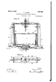
- Figure 1 is a side view in elevation, partly broken away, illustrating my improved mechanism in connection with a machine for forming aspirally wound conduit;
- Figure 2 is a view in vertical or longitudinal section illustrating my improved mechanism per se
- FIG. 3 is a top plan view of the upper portion only of the mechanism shown in Flgure- 2;
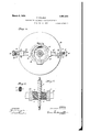
- FIG. 4 is an inverted plan view on the l1ne 44 of Figure 2;
- Figure 5 is a view partly in section and partly 1n elevation illustrating on an enlarged scale the shape of the pressure dies with the conduit therein during tlTe o-perat1on of flattening the conduit;
- Figure 6 is a view in transverse section through the flattened conduit, taken on the line 66 of Figure 5.
- A represents a machine for making or forming a spirally wound conduit of the type referred to.
- Said conduit indicated b the reference numeral 1 is composed of strips 2, 2, properly shaped and spirally wound around a pa1r of insulated conductors 3, 3, which said conduit encloses.
- the convolutions of the conduit are interengaged or interlocked so that they will not accidentally separate, and, as is customary, the machine A makes this conduit of general cylindrical form, and it is the purpose of my improved mechanism to flatten this conduit either as the conduit comes from the machine A or, of course, from any other source.
- This receptacle 4 has blocks 5, 5 projecting downwardly from its bottom and at opposite sides thereof, and is supported centrally by the enlarged or flanged upper end 6 of a vertically disposed shaft 7, said receptacle being secured by screws, bolts, or other attaching means 8 to the said flanged or enlarged end 6, as clearly shown in Figure 2.
- a hub 9 is mounted to turn, and this hub at its lower end has an annular flange 10 which is fixedly secured to a base 11 so that the hub is held against turning movement.
- a pair of 100 oppositely disposed eccentrics 12, 13 are located and fixedly secured or made integral with the hub.
- Crossbars 18 connect theouter ends of the pairs of rods 16 and 17, respectively, and
- These rods 19 are slotted, as indicated at 20, to receive the rounded lower ends of levers 21.
- These levers21 are located at opposite sides of the receptacle 4 and are pivotally supported near their upper ends in brackets 22, the latter being fixed to upri hts 23 mounted on aplate 24 which constitutes the bottom of the receptacle 4 and extends outwardly beyond the side walls of said receptacle.
- These rods 23 are arranged in pairs and they are connected at their upper ends by guide bars 25, 25, which are spaced apart or located in parallelism and are disposed the proper distance above the top 26 of receptac e 4. This top 26 has a 'receptacle opening 27 therein through which the flattened conduit 1 is permitted to feed into the receptacle.
- the guide bars 25, 25 provide mounting for a pair of sliding blocks 28, 29, respectively, said blocks being grooved to receive the bars and permitted a free reciprocating movement between the bars but held against lateral displacement.
- each convolution receives in regular succession a sequence of pressure contacts, so that while the first contact of a convolution flattens said convolution slightly, the last contact of said convolution by said dies completes the flattening operation.
- the invention is not limited to the particular shape of the die as this is capable of modification, the function being of course to change the shape of the conduit from cylindrical to flattened or elliptical form, but I believe the arrangement illustrated is prefarable.
- the bars 25, 25 support a frame 32 which is provided with guides 34 and 35 above and below the horizontal plane of the dies 31, as indicated clearly in Figure 2. The conheld thereby for properly positioning them in contact with the dies, the upper guide 34 having an internal shape to receive the cylindrical conduit, and the lower guide 35 having an internal shape to receive the flattened conduit, and said conduit passing freely through said guides during the operation of the mechanism.
- shaft 7 above described is operatively connectcd to turn with the moving parts of the machine A, and while I have illustrated by dot and dash lines in the lower portion of Figure 1 intermcshing gearing for operatively connecting the shaft 7 to the mechanism of machine A it is obvious that the invention is not limited to any particular driving means but, as stated above, it is entirely practicable and in many cases desirable to have my mechanism flatten the conduit as it was received from the machine which makes the conduit, so that there may be a synchronism or co-ordination of the movements of the several parts in order to carry out the operation with precision and secure a uniform product.
- duit 1 passes through these guides and is including a pair of reciprocating members we havin rotary mounting and between which a turning conduit is adapted to be positioned, and dies on said mem ers adapted to engage opposite sides of the conduit and flatten the same, said dies so shaped as to subject the independent convolutions of the conduit to a step by step pressure operation.
- a mechanism of the character described including a pair of reciprocating members adapted to receive a conduit between them, a ppir of levers pivoted between their ends, lin s connecting the levers and said reciprocating members, a receptacle ada ted to turn and carry the levers with it, sai receptacle adapted to receive the conduit and 0011 the same therein, and means for imparting pivotal movement to the levers.
- a mechanism of the character described including a rotary receptacle, a shaft sup porting said receptacle, u rights on the receptacle, levers fulcrumed etween their ends on the u rights, guide bars connecting the upper en s of the uprights, blocks mounted to slide between said bars, conduit engaging dies on said blocks, links connecting the blocks and the upper ends of the levers, fixed eccentrics below the rece tacle, straps or hands on said eccentrics, locks de endin from the receptacle, and rods guided in sai blocks and connected to the straps and the lower ends of the levers respectivel 4.
- said attachment In combination with a mac ine for forming spirally wound conduits, of an attachment for flattening said conduits, said attachment including reciprocatin dies for engagement with opposite sides 0 the conduit, and means connecting the conduit formmachine and said attachment whereby said machine and dies are caused to operate in synchronism and unison.
Landscapes
- Engineering & Computer Science (AREA)
- Mechanical Engineering (AREA)
- Manufacturing & Machinery (AREA)
- Shaping Of Tube Ends By Bending Or Straightening (AREA)
Description
March 6, 1928. 1,661,908
F. PALMER MACHINE FOR FLATTENING TUBULAR MATERIALS Filed Dec. 9. 1926 s Sheets-Sheet 1 c J E J I EM/ENTOR HTHESSES 7/ FREDERICK PALMER v V ,y 964 A a 1/ a B Y jWC'iEZ W LMMMA ATTORNEY March 6, 1928.
F. PALMER mourns FOR FLATTENING TUBULAR MATERIALS Filed Dec. 9. 1926 5 Sheets-Sheet 2 IIIIIIIIIII iNVENTOR FEEIZSEIOKJ /JLMEIZ w Mai a LL ATTORNEY Patented Mar. 6, 1928.
UNITED STATES PATENT OFFICE.
FREDERICK PALMER, F BROOKLYN, NEW YORK, ASSIGNOR TO TRIANGLE CONDUI'I 00., 0] BROOKLYN, NEW YORK, A CORPORATION OF NEW YORK.
MACHINE FOR FLATTENING TUBULAR MATERIALS.
Application filed December 9, 1926. Serial N0. 168,717.
This invention relates to machines for fiattening tubular materials and has particularly to do with means or mechanism for flattening spirally wound cable armors.
I Such armor is made first in cylindrical form and is then flattened by my improved mechanism, which is preferably although not essentially so arranged as to work in unison with the machine which forms the conduit and which functions as an additional operation as a part of said machine.
It is of course to be understood that my improved mechanism is not dependent upon any particular type of machine which forms the conduit but has to do solely with the means for flattening the conduit.
Fla-ttened conduits are desirable in many places in building constructions, and such conduits usually contain a pair of insulated contacts, and while my invention has particularly to do with the flattening of this type of conduit and will be described in connection with the same, it is to be distinctly understood that the invention is broad enough to cover other forms of tubular material which it is desirable to flatten.
An object of the invention is to provide means of this character which will exert uniform pressure at op osite sides of the conduit through the me ium of dies which conform in shape to the shape of a flattened conduit, the flattening operation being carried out step by step as the conduit is moved between the pressure dies, so that the compression of the several convolutions is gradually carried out to bring the convolutions from cylindrical form to a flattened 0r elliptical form.
With these and other objects in view, the
invention consists in certain novel features of construction and combinations and arrangements of parts, which will be more fully hereinafter described and pointed out in the claims.
In the accompanying drawings- Figure 1 is a side view in elevation, partly broken away, illustrating my improved mechanism in connection with a machine for forming aspirally wound conduit;
Figure 2 is a view in vertical or longitudinal section illustrating my improved mechanism per se;
L Figure 3 is a top plan view of the upper portion only of the mechanism shown in Flgure- 2;
I Figure 4 is an inverted plan view on the l1ne 44 of Figure 2;
Figure 5 is a view partly in section and partly 1n elevation illustrating on an enlarged scale the shape of the pressure dies with the conduit therein during tlTe o-perat1on of flattening the conduit;
Figure 6 is a view in transverse section through the flattened conduit, taken on the line 66 of Figure 5.
A represents a machine for making or forming a spirally wound conduit of the type referred to. Said conduit indicated b the reference numeral 1 is composed of strips 2, 2, properly shaped and spirally wound around a pa1r of insulated conductors 3, 3, which said conduit encloses. The convolutions of the conduit are interengaged or interlocked so that they will not accidentally separate, and, as is customary, the machine A makes this conduit of general cylindrical form, and it is the purpose of my improved mechanism to flatten this conduit either as the conduit comes from the machine A or, of course, from any other source.
I have indicated,.however, in Figure 1 my improved mechanism as constituting a part of or a continuation of the machine A, 10- eating my improved mechanism below the machine A so that the conduit will feed downwardly, and after being flattened will coil within a receptacle 4.
This receptacle 4 has blocks 5, 5 projecting downwardly from its bottom and at opposite sides thereof, and is supported centrally by the enlarged or flanged upper end 6 of a vertically disposed shaft 7, said receptacle being secured by screws, bolts, or other attaching means 8 to the said flanged or enlarged end 6, as clearly shown in Figure 2.
On this shaft 7, a hub 9 is mounted to turn, and this hub at its lower end has an annular flange 10 which is fixedly secured to a base 11 so that the hub is held against turning movement. On the hub 9 a pair of 100 oppositely disposed eccentrics 12, 13 are located and fixedly secured or made integral with the hub.
On these eccentrics 12 and 13 bands or straps 14 and 15, respectively, are mounted, the and 14 being secured to a pair of reciprocating rods 16 aided in their movement through one o the blocks 5, and the other band or strap 15 is fixedly secured to a pair of rods 17 which are guided in their movement through the other block 5.
Crossbars 18 connect theouter ends of the pairs of rods 16 and 17, respectively, and
to each of these crossbars 18 relatively short rods 19 are secured and are disposed between the pairs of eccentric rods above described and parallel therewith, and are also guided in their movements through the blocks 5.
These rods 19 are slotted, as indicated at 20, to receive the rounded lower ends of levers 21. These levers21 are located at opposite sides of the receptacle 4 and are pivotally supported near their upper ends in brackets 22, the latter being fixed to upri hts 23 mounted on aplate 24 which constitutes the bottom of the receptacle 4 and extends outwardly beyond the side walls of said receptacle. These rods 23 are arranged in pairs and they are connected at their upper ends by guide bars 25, 25, which are spaced apart or located in parallelism and are disposed the proper distance above the top 26 of receptac e 4. This top 26 has a 'receptacle opening 27 therein through which the flattened conduit 1 is permitted to feed into the receptacle.
The guide bars 25, 25 provide mounting for a pair of sliding blocks 28, 29, respectively, said blocks being grooved to receive the bars and permitted a free reciprocating movement between the bars but held against lateral displacement.
The blocks 28, 29 are connected by links 30 with the upper ends of levers 21, and said blocks carry die members 31 on their inner faces which are of the shape indicated most clearly in Figure 5. As these dies move toward each other their function is to change the shape of the cylindrical conduit to a flattened or elliptical conduit, and this change of shape is brought about gradually step by step. In other words, each convolution receives in regular succession a sequence of pressure contacts, so that while the first contact of a convolution flattens said convolution slightly, the last contact of said convolution by said dies completes the flattening operation.
It is of course to be understood that the invention is not limited to the particular shape of the die as this is capable of modification, the function being of course to change the shape of the conduit from cylindrical to flattened or elliptical form, but I believe the arrangement illustrated is prefarable.
The bars 25, 25 support a frame 32 which is provided with guides 34 and 35 above and below the horizontal plane of the dies 31, as indicated clearly in Figure 2. The conheld thereby for properly positioning them in contact with the dies, the upper guide 34 having an internal shape to receive the cylindrical conduit, and the lower guide 35 having an internal shape to receive the flattened conduit, and said conduit passing freely through said guides during the operation of the mechanism.
In Figure 1 I illustrate my improvement in connection with the machine A, which forms the conduit, and when so used, the
The operation is as follows:
Assuming that the machine A is forming the conduit and that the latter is moving' downwardly, at the same timemotion is transmitted to the shaft 7 to revolve the receptacle 4, and this movement of the receptacle 4 carries with it a turning or retary movement of standards 23, levers 21, bars 25, blocks 5 and rods 16; hence, as these parts turn the straps 14 and 15 on the eccentrices 12 and 13, respectively, they cause a reciprocating movement to be imparted to the rods 16 and 17 and of course to the rods 19 as well.
As these rods 19 move inwardl and outwardly, the levers 21 are move on their pivots to impart a reciprocating movement to the blocks 28 and 29 and the die members 31 so as to bring said die members into contact with the opposite sides of the conduit to flatten the same, as above explained. As the flattened conduit moves downwardly through the opening 27 in the revolving receptacle 4, it will be caused to coil in said receptacle as it accumulates, as will be readily understood.
While I have illustrated what I believe to be a preferred embodiment of my invention it is to be distinctly understood that I do not limit myself to the specific construction set forth but consider myself at liberty to make such changes and alterations as fairly fall within the spirit and scope of the appended claims.
I claim:
1. A. mechanism of the character described,
2. A mechanism of the character described, including a pair of reciprocating members adapted to receive a conduit between them, a ppir of levers pivoted between their ends, lin s connecting the levers and said reciprocating members, a receptacle ada ted to turn and carry the levers with it, sai receptacle adapted to receive the conduit and 0011 the same therein, and means for imparting pivotal movement to the levers.
3. A mechanism of the character described, including a rotary receptacle, a shaft sup porting said receptacle, u rights on the receptacle, levers fulcrumed etween their ends on the u rights, guide bars connecting the upper en s of the uprights, blocks mounted to slide between said bars, conduit engaging dies on said blocks, links connecting the blocks and the upper ends of the levers, fixed eccentrics below the rece tacle, straps or hands on said eccentrics, locks de endin from the receptacle, and rods guided in sai blocks and connected to the straps and the lower ends of the levers respectivel 4. In combination with a mac ine for forming spirally wound conduits, of an attachment for flattening said conduits, said attachment including reciprocatin dies for engagement with opposite sides 0 the conduit, and means connecting the conduit formmachine and said attachment whereby said machine and dies are caused to operate in synchronism and unison.
5. In combination with a machine for forming spirally wound conduits and imparting a turning motion ,to the conduits during the formation thereof, of a rotary support, and reciprocating dies on the rotary support for engagement with opposite sides of the conduit while the latter is turn- 1n In combination with a machine for forming spirally wound conduits and imparting a turning motion to the conduits during the formation thereof, of a rotary support, and reciprocating dies on the rotary support for engagement with the opposite sides of the conduit while the latter is turning, said support including a receptacle in which the conduit is coiled.
FREDERICK PALMER.
Priority Applications (1)
| Application Number | Priority Date | Filing Date | Title |
|---|---|---|---|
| US153717A US1661908A (en) | 1926-12-09 | 1926-12-09 | Machine for flattening tubular materials |
Applications Claiming Priority (1)
| Application Number | Priority Date | Filing Date | Title |
|---|---|---|---|
| US153717A US1661908A (en) | 1926-12-09 | 1926-12-09 | Machine for flattening tubular materials |
Publications (1)
| Publication Number | Publication Date |
|---|---|
| US1661908A true US1661908A (en) | 1928-03-06 |
Family
ID=22548429
Family Applications (1)
| Application Number | Title | Priority Date | Filing Date |
|---|---|---|---|
| US153717A Expired - Lifetime US1661908A (en) | 1926-12-09 | 1926-12-09 | Machine for flattening tubular materials |
Country Status (1)
| Country | Link |
|---|---|
| US (1) | US1661908A (en) |
Cited By (3)
| Publication number | Priority date | Publication date | Assignee | Title |
|---|---|---|---|---|
| US2430210A (en) * | 1945-04-17 | 1947-11-04 | Griscom Russell Co | Method and apparatus for making finned tubing |
| US2452125A (en) * | 1945-06-12 | 1948-10-26 | Titeflex Inc | Method of forming and changing the cross section of convoluted metal tubing |
| US3643484A (en) * | 1969-12-18 | 1972-02-22 | Nikolai Nikolaevich Orlov | Device for forming projections on sides of hollow details |
-
1926
- 1926-12-09 US US153717A patent/US1661908A/en not_active Expired - Lifetime
Cited By (3)
| Publication number | Priority date | Publication date | Assignee | Title |
|---|---|---|---|---|
| US2430210A (en) * | 1945-04-17 | 1947-11-04 | Griscom Russell Co | Method and apparatus for making finned tubing |
| US2452125A (en) * | 1945-06-12 | 1948-10-26 | Titeflex Inc | Method of forming and changing the cross section of convoluted metal tubing |
| US3643484A (en) * | 1969-12-18 | 1972-02-22 | Nikolai Nikolaevich Orlov | Device for forming projections on sides of hollow details |
Similar Documents
| Publication | Publication Date | Title |
|---|---|---|
| US2741079A (en) | Apparatus for continuous production of filled and sealed tetrahedral packages of paper or the like | |
| US1661908A (en) | Machine for flattening tubular materials | |
| US3009510A (en) | Apparatus and method for corrugating sheet metal strip | |
| US1917359A (en) | Can making machine | |
| US3930440A (en) | Device for conveying rolled food | |
| US2378058A (en) | Apparatus to change the length of corrugated wires | |
| US2305266A (en) | Wire bending machine | |
| US2798416A (en) | Box making die | |
| US2483865A (en) | Sinusoidal spring forming machine | |
| US2440792A (en) | Method and means for forming rectangular flexible metal tubing | |
| US1594326A (en) | Blank-reversing device for drawing presses | |
| US2308591A (en) | Conveyer | |
| US3525096A (en) | Method of forming u-shaped clips of noncircular cross section | |
| US2170289A (en) | Mechanism for feeding sheet material and the like | |
| US2676621A (en) | Wire forming machine | |
| US2456353A (en) | Wire-bending machine | |
| US3128961A (en) | wickwire | |
| US1576011A (en) | Ice-cream-cone-rolling machine | |
| US1327467A (en) | Machine for making fabricated wire | |
| US2160020A (en) | Wire bending machine | |
| US3208484A (en) | Wire coil binding machines | |
| US1758699A (en) | Straightening machine | |
| SU387769A1 (en) | YSSOYUZKAL | |
| US2691714A (en) | Welding machine | |
| US1388428A (en) | Machine for making packing |