US1646292A - Method op directing light rats upon light sensitive elements - Google Patents
Method op directing light rats upon light sensitive elements Download PDFInfo
- Publication number
- US1646292A US1646292A US1646292DA US1646292A US 1646292 A US1646292 A US 1646292A US 1646292D A US1646292D A US 1646292DA US 1646292 A US1646292 A US 1646292A
- Authority
- US
- United States
- Prior art keywords
- light
- orifice
- rays
- rats
- directing
- Prior art date
- Legal status (The legal status is an assumption and is not a legal conclusion. Google has not performed a legal analysis and makes no representation as to the accuracy of the status listed.)
- Expired - Lifetime
Links
- 238000000034 method Methods 0.000 title description 5
- 241000700159 Rattus Species 0.000 title 1
- 239000000463 material Substances 0.000 description 4
- 230000005540 biological transmission Effects 0.000 description 3
- 238000010276 construction Methods 0.000 description 3
- 239000000428 dust Substances 0.000 description 3
- 239000011521 glass Substances 0.000 description 2
- 230000003287 optical effect Effects 0.000 description 2
- 229920001342 Bakelite® Polymers 0.000 description 1
- 241000283690 Bos taurus Species 0.000 description 1
- 101100025924 Caenorhabditis elegans gei-8 gene Proteins 0.000 description 1
- 244000025254 Cannabis sativa Species 0.000 description 1
- 235000012766 Cannabis sativa ssp. sativa var. sativa Nutrition 0.000 description 1
- 235000012765 Cannabis sativa ssp. sativa var. spontanea Nutrition 0.000 description 1
- 239000004637 bakelite Substances 0.000 description 1
- 235000009120 camo Nutrition 0.000 description 1
- 235000005607 chanvre indien Nutrition 0.000 description 1
- 239000011248 coating agent Substances 0.000 description 1
- 238000000576 coating method Methods 0.000 description 1
- 239000012141 concentrate Substances 0.000 description 1
- 239000010432 diamond Substances 0.000 description 1
- 229910003460 diamond Inorganic materials 0.000 description 1
- 239000011487 hemp Substances 0.000 description 1
- 239000002184 metal Substances 0.000 description 1
- 238000012986 modification Methods 0.000 description 1
- 230000004048 modification Effects 0.000 description 1
- 239000003973 paint Substances 0.000 description 1
- 239000002245 particle Substances 0.000 description 1
- 239000010453 quartz Substances 0.000 description 1
- 239000010979 ruby Substances 0.000 description 1
- 229910001750 ruby Inorganic materials 0.000 description 1
- VYPSYNLAJGMNEJ-UHFFFAOYSA-N silicon dioxide Inorganic materials O=[Si]=O VYPSYNLAJGMNEJ-UHFFFAOYSA-N 0.000 description 1
- MLGCXEBRWGEOQX-UHFFFAOYSA-N tetradifon Chemical compound C1=CC(Cl)=CC=C1S(=O)(=O)C1=CC(Cl)=C(Cl)C=C1Cl MLGCXEBRWGEOQX-UHFFFAOYSA-N 0.000 description 1
Images
Classifications
-
- H—ELECTRICITY
- H04—ELECTRIC COMMUNICATION TECHNIQUE
- H04N—PICTORIAL COMMUNICATION, e.g. TELEVISION
- H04N1/00—Scanning, transmission or reproduction of documents or the like, e.g. facsimile transmission; Details thereof
- H04N1/024—Details of scanning heads ; Means for illuminating the original
Definitions
- ..Aifurther object of my :invention is to lar outline. It isiinponcant that the light i provide a construction or' oritioe .for direct -he concentrated forthe purpose of .making ving liglit-irays in a, concentrated beam upon n V definite .record on i the filmjnndgthat thea light sensitive object, where light may be orifice or aperture does not clog 'up .,witli Vfree1y passed through the orifice while an fparticles of diist.
- -It is also important that .opaque wall is provided nroiiiidthe orifice ,the light or1fice ,y does notscratch thelfilm i for concentrating the rays of lightl ⁇ throiigh rind that it be in vclose proximityvtorthe film' fthe orifice against the light sensitive-object. in order to obtain ajsharp record. pf-1;? i y
- My invention consists of ay transparent 30 to provide a. construction of orifice foi-.dimaterial such as glass, quartz.
- the materuil hasy a transparent lateral' photographic transmission and reception of axis through which the light rnys may be telegrnphic signals.
- light is ⁇ used'as passedq while anlopaqu@ Surface 15 provxde 1 .i the medium for reproducing an object 0n for concentratin the light rays in the diff a sensitized film or plate or for vaprying the reciion of the critico.
- i i p degree of conductivity of a light'sehsitive Mv ⁇ invention will he more clearly mmm.. eell. It is well known in the nrt of tiansstood from the speciilcation hereinafter :FDL
- a sensitive film may be moving in orifice constructed in accordance with myV y order to record the vibrations or changes in invention and arranged with lnton them.
- 105 4 y light intensity which correspond to the freto;
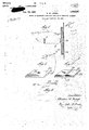
- Fig. 2. is o, perspective viewof one form 1 y f quency of sound vibrations or to the elein which the light orifice of my invention f f il Y ments of ictures or messages. In some may be constructed: Fig.
- Sissi perspective methods sheam of light is swung back and view 0f a further mo'de cgngtriictionof M forth over a slit and results in a wavy line light Orifice; and
- Fig is an end view of 11o' l5 is hen mounted in a holder of any suitable a source-mt li ht rays, means for concen- :g3 Y Leganes the light orifice of the form of my inventhat in practice the orifice is extremel mition shown in Fig. 3. nute.
- the surface 24 of the plate 23 may be renvention are intended other than are imposed ,10 dered opaque by a covering of paint or bythe scope ofthe appended claims.y . ⁇ enarnel applied to the surface or by means lVhat I claim ns new and desire to secure a color such as ruby or orange or other by Letters Patent of the United States is asf safe light which ma be flashed on or follows: tire/d in the surface o? the plate.V The cone 1.
- the combination oi material such as glass', bakelite, metal of any tratingsaid lig t rays in a beam, means dikind or any other material which will 'suprectly adjacent a lig t sensitive element for 60 port the plateadjacent the film "8. directing said beam of light rays thereupon, n
- the transparent plate 23 is' formed with a comprising a fiat transparent sheet of ma-v ein sli ht. oirit 26 or longitudinally extending terial, a raised-portion in the shape of a ⁇ v ri gei 8 as shown in ⁇ Figs. 3 and 4 and the ⁇ 'lght orifice on one side'of said flat sheet of opaque color 24 applied t6 the surface ofthe material and located directly adjacent said. e5 l e p ate 23.
- the point 26 or ridge 28 may light sensitive element, and an opaque coat- 1 l then be ground od flush with the remaining ing on the side of said plate surrounding 26 surface therebyv providing a transparent said orifice for directing all of saiddght ⁇ lightl rays..
- the light rays may be further 2.
- the plate 23 conforming means direct y adjacent a lig t sensitive elee l A '35 closely adiaceni'l the film' forming a small tion thereof raised out o pinic4 dr line for the transmission of the ⁇ rays throu h said orifice.
- the lens portion 27 may be circular or it thereupon, comprising a. .fiat sheet of ma- 'I5 l "f may extend laterally across the plate 23.
Landscapes
- Engineering & Computer Science (AREA)
- Multimedia (AREA)
- Signal Processing (AREA)
- Optical Elements Other Than Lenses (AREA)
Description
` 1 wh??? l', l 'XK/C( czymknnuslri l, d
METHOD oF DIREGTINGLIGHT Rus vrou 4.LIGHT SENSITIVE ELEMENTS origiggl Filed ook. 22.l 1925 l j* i or radio signals to cause ii -beam of light to drawing. in which; A
enemies oci. is, 19er. 1,645,292 @New STATES 'Pemieuise- CLI'NTON W. BOUGE. OF BOONVILLENEW YORK, ASSIGNQBO WIRED BADIU, man 0F l New your, N. Y., AconPonA'rIoN or'fpnnnwnsin.` .j ,j' A- I METHOD or Dmnc'riive morir nAYs upon Liann-SENSITIVE miams. 'i'
Application ined october 2a, 192s, sensi no. .64,153. Renewed .ingaat imiter. My invention relates broadly to optics and o f light being impressed on the-moving senmore particularly to methods of directing sitized film. In other systems the intensity light upon light sensitive elements, such as of the light beam is varied and-a line/of sensitized films, plates or light sensitive va ing intensity* or of intermittent bands t ce ls. S a. `r l i 1w 1 or ots of` light are recorded on the film. V In Y One of the obje ts of my invention 'is tommking slits or openings,` through which the 1' `provide a metho of directing light upon hemp of light gasses to the sensitive film,it ight sensitive elements, such as sensitive is ditlicult to a just these accurately because 51mg, plates or igt/segsgiyells in siiclreof` the rather small" dimensions of the slit, lo manner that the orifice through which the and in operation the slit or other shaped orii y Llight passes is maintained clear of dust parfice rapidly vbecomes clogged with particles "ticlcsV or other foreign matter at all times lof dust or fronrparticles ofthe film sotht f to prevent interference .with theiree passai: the volume of light passing through isp-rej --if the rays of light therethrough; g duced or entirely shut/E.` Light apertures l5' Still another object of my invention is to of ,various shapes fand' dimensions are :rev rovide 'n construction of orifice `for directquired. ,They may be in the shape of a, longiing light in a. beam of a desired shape and tudiniil line of light of'any required width issize, while preventing interferenceby `dust "nnd length orin thejsha'peof si.concentriited,` `particles or foreign matter. ,with-thc, free ivhichmay becircular.=oval,` squaijeyi" 2o passage of li glit rays through the orifice. -pf-rectanfznlar or ofany v,geometrical or irrepgii;`
..Aifurther object of my :invention is to lar outline. It isiinponcant that the light i provide a construction or' oritioe .for direct -he concentrated forthe purpose of .making ving liglit-irays in a, concentrated beam upon n V definite .record on i the filmjnndgthat thea light sensitive object, where light may be orifice or aperture does not clog 'up .,witli Vfree1y passed through the orifice while an fparticles of diist. -It is also important that .opaque wall is provided nroiiiidthe orifice ,the light or1fice ,y does notscratch thelfilm i for concentrating the rays of lightl` throiigh rind that it be in vclose proximityvtorthe film' fthe orifice against the light sensitive-object. in order to obtain ajsharp record. pf-1;? i y A still further object of my invention is My invention consists of ay transparent 30 to provide a. construction of orifice foi-.dimaterial such as glass, quartz. diamond or rectiiig light against ii light sensitive object other substancehaving nl portion thereoll where various shapes sind sizcs mavgbe rezid- .rendered opaque. to thetraiismission of light ily im tdther'ficeand the light conrays and a portion arranged to concentrate ned in a"path'tl6ugh`the orifice bv on light rays in ii predetermined direction. 85 opaque surface covering located aroun the The transparent materriihmntalre any de orifice. sired shape in accordance withthshape of My invention' has particular reference to orifice which it is necessary to present to television, the transmission and reception of the sensitive filin. plate or 4light sensitive` pictures by line wire orspace radio. and the cell. The materuil hasy a transparent lateral' photographic transmission and reception of axis through which the light rnys may be telegrnphic signals. where light is` used'as passedq while anlopaqu@ Surface 15 provxde 1 .i the medium for reproducing an object 0n for concentratin the light rays in the diff a sensitized film or plate or for vaprying the reciion of the critico. i i p degree of conductivity of a light'sehsitive Mv` invention will he more clearly mmm.. eell. It is well known in the nrt of tiansstood from the speciilcation hereinafter :FDL
:uiittingA pictures or images by telegraph lowing. by reference tothe accompanying' ".r
pass through a UITOW slit o r orifice hehind ilgiire lshowsnn optical system and light 1 Y which a sensitive film may be moving in orifice constructed in accordance with myV y order to record the vibrations or changes in invention and arranged with lnton them. 105 4 y light intensity which correspond to the freto; Fig. 2. is o, perspective viewof one form 1 y f quency of sound vibrations or to the elein which the light orifice of my invention f f il Y ments of ictures or messages. In some may be constructed: Fig. Sissi perspective methods sheam of light is swung back and view 0f a further mo'de cgngtriictionof M forth over a slit and results in a wavy line light Orifice; and Fig, is an end view of 11o' l5 is hen mounted in a holder of any suitable a source-mt li ht rays, means for concen- :g3 Y Leganes the light orifice of the form of my inventhat in practice the orifice is extremel mition shown in Fig. 3. nute. In order to-properlyillustrate t e in- 45j Referrin to the drawings in more detail# vgintion, however, I have multiplied thesize reference c aracter 1 'represents a source o iof' the orifice many times. 5 iight rays which are focused through lens 2. I have illustrated my invention in certain and directed upon the light orifice 23. As referred embodiment-s, but I desire that it shown more articularly 1n Fig. 2 the light e understood that modifications" may' be 60 orifice may e formed from flat materlal. made and that no limitations upon the in- The surface 24 of the plate 23 may be renvention are intended other than are imposed ,10 dered opaque by a covering of paint or bythe scope ofthe appended claims.y .\enarnel applied to the surface or by means lVhat I claim ns new and desire to secure a color such as ruby or orange or other by Letters Patent of the United States is asf safe light which ma be flashed on or follows: tire/d in the surface o? the plate.V The cone 1. In an optical system the combination oi material such as glass', bakelite, metal of any tratingsaid lig t rays in a beam, means dikind or any other material which will 'suprectly adjacent a lig t sensitive element for 60 port the plateadjacent the film "8. directing said beam of light rays thereupon, n
I The transparent plate 23 is' formed with a comprising a fiat transparent sheet of ma-v ein sli ht. oirit 26 or longitudinally extending terial, a raised-portion in the shape of a` v ri gei 8 as shown in `Figs. 3 and 4 and the^'lght orifice on one side'of said flat sheet of opaque color 24 applied t6 the surface ofthe material and located directly adjacent said. e5 l e p ate 23. `The point 26 or ridge 28 may light sensitive element, and an opaque coat- 1 l then be ground od flush with the remaining ing on the side of said plate surrounding 26 surface therebyv providing a transparent said orifice for directing all of saiddght` lightl rays.. The light rays may be further 2. In a ight directing system f 30 'opposite surface of. the plate 23 conforming means direct y adjacent a lig t sensitive elee l A '35 closely adiaceni'l the film' forming a small tion thereof raised out o pinic4 dr line for the transmission of the `rays throu h said orifice.
concentrated through the orifice by meanso nation of a source. of light rays, means for a lens 27 or 29 which may be formed on the 'concentratin said light ra s in a beam,l f"
in shape with the point 26 or ridge 28, that ment for directing said beam of light rays f is the lens portion 27 may be circular or it thereupon, comprising a. .fiat sheet of ma- 'I5 l "f may extend laterally across the plate 23. terial transparent to l he passage of light The raised portion.26 or 28 is positioned rays, said material having an integral or y the plane o itsv 1 light slit which dust or other articles from surface and sha ed to provide a light orifice fr the lm cannot clog up and w ich will eontransparent to -ie passa e of li ht rays and S0 vcentrate the light u on the sound record oi" an opaque coating on he surace of said the film for repro uction of sound therelate immediately surroundin said orifice 40 from at maximum ampiitude. f or restricting the passage of ht through "It will be understood that the size of the said plate to the area of said or' ce. Y
light orifices have been shown greatly ex- In testimony whereofI aiiix Img i G ture- H sggmed in Size and it wie be understood CLINTON W.
Publications (1)
| Publication Number | Publication Date |
|---|---|
| US1646292A true US1646292A (en) | 1927-10-18 |
Family
ID=3413606
Family Applications (1)
| Application Number | Title | Priority Date | Filing Date |
|---|---|---|---|
| US1646292D Expired - Lifetime US1646292A (en) | Method op directing light rats upon light sensitive elements |
Country Status (1)
| Country | Link |
|---|---|
| US (1) | US1646292A (en) |
Cited By (4)
| Publication number | Priority date | Publication date | Assignee | Title |
|---|---|---|---|---|
| US2420503A (en) * | 1944-08-31 | 1947-05-13 | Bell & Howell Co | Optical reticle |
| US5665957A (en) * | 1995-08-30 | 1997-09-09 | Samsung Electronics Co., Ltd. | Lens device comprising light blocking means and an optical pickup apparatus using the lens device |
| US5907530A (en) * | 1995-08-30 | 1999-05-25 | Samsung Electronics Co., Ltd. | Optical pickup device |
| USRE39025E1 (en) * | 1995-08-30 | 2006-03-21 | Samsung Electronics Co., Ltd. | Lens device including a light controlling mechanism and an optical pickup apparatus using a lens device |
-
0
- US US1646292D patent/US1646292A/en not_active Expired - Lifetime
Cited By (6)
| Publication number | Priority date | Publication date | Assignee | Title |
|---|---|---|---|---|
| US2420503A (en) * | 1944-08-31 | 1947-05-13 | Bell & Howell Co | Optical reticle |
| US5665957A (en) * | 1995-08-30 | 1997-09-09 | Samsung Electronics Co., Ltd. | Lens device comprising light blocking means and an optical pickup apparatus using the lens device |
| US5822135A (en) * | 1995-08-30 | 1998-10-13 | Samsung Electronics Co., Ltd. | Lens device including a light controlling mechanism and an optical pickup apparatus using a lens device |
| US5907530A (en) * | 1995-08-30 | 1999-05-25 | Samsung Electronics Co., Ltd. | Optical pickup device |
| US5987924A (en) * | 1995-08-30 | 1999-11-23 | Samsung Electronics Co., Ltd. | Lens mold and method of manufacturing a lens |
| USRE39025E1 (en) * | 1995-08-30 | 2006-03-21 | Samsung Electronics Co., Ltd. | Lens device including a light controlling mechanism and an optical pickup apparatus using a lens device |
Similar Documents
| Publication | Publication Date | Title |
|---|---|---|
| US1646292A (en) | Method op directing light rats upon light sensitive elements | |
| US2118894A (en) | Apparatus for producing combined sound and motion picture films | |
| US2031835A (en) | Recording and reproduction of electrical impulses | |
| US2097141A (en) | Photophonographic apparatus | |
| US2095317A (en) | Photographic sound recorder | |
| US2283545A (en) | Light modulating method and apparatus | |
| US2220198A (en) | Monitoring system | |
| US1801472A (en) | Sound-reproducing system | |
| US2095909A (en) | Universal screen for preparing half tones | |
| US1980223A (en) | Light valve for translation of sound effects | |
| US2354295A (en) | Sound recording system | |
| US2097657A (en) | Photographic recording of sound | |
| US1912156A (en) | Optical system | |
| US1659570A (en) | Transmission of pictures by electricity | |
| US2044188A (en) | Method of modulating light for the photoelectric impression of sound on a photosensitive surface | |
| US1917653A (en) | Sound track mechanism | |
| US2165777A (en) | Impulse recorder | |
| US2468049A (en) | Photographic sound recording system and aperture plate therefor | |
| US1940937A (en) | Sound recording and reproducing system | |
| US1683451A (en) | Sound recording and reproducing apparatus | |
| US2073773A (en) | Photoelectric converter | |
| US1859243A (en) | Means and method for recording photographic sound records | |
| US2042619A (en) | Noiseless recording | |
| US2268097A (en) | Sound recording apparatus | |
| US2299024A (en) | Optical system |