US1631908A - Rigid airship - Google Patents
Rigid airship Download PDFInfo
- Publication number
- US1631908A US1631908A US741240A US74124024A US1631908A US 1631908 A US1631908 A US 1631908A US 741240 A US741240 A US 741240A US 74124024 A US74124024 A US 74124024A US 1631908 A US1631908 A US 1631908A
- Authority
- US
- United States
- Prior art keywords
- girders
- truss
- rigid
- ring
- airship
- Prior art date
- Legal status (The legal status is an assumption and is not a legal conclusion. Google has not performed a legal analysis and makes no representation as to the accuracy of the status listed.)
- Expired - Lifetime
Links
Images

Classifications
-
- B—PERFORMING OPERATIONS; TRANSPORTING
- B64—AIRCRAFT; AVIATION; COSMONAUTICS
- B64B—LIGHTER-THAN AIR AIRCRAFT
- B64B1/00—Lighter-than-air aircraft
Definitions
- My invention relates to the hulls of rigid air-ships which are made up of longltudinal and cross members, particularly to the construction of the cross members which are called rings and generally have apolygonal shape.
- the sides of the polygon cons1st of girders, and such girders are braced'by 1nternal wire bracing. All this construction is situated in one plane and this plane is.
- a ring construction embodying my invention ermits of loads to be distributed on the ower arts thereof, especially when the rings orm corridors e2;- tending at right angles from the longitudinal corridor usual with ri d airships.
- the provision of a number 0 [such cross corridors facilitates the supervision of the hull structure .and especially that of the walls of the gas cells during the flights, which is of hi hest importance.
- a longitudinal corridor at the ridge of the ship will permit supervision of the operated valves during flight, which is an advantage of greatest value.
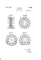
- Fig. 1 is a cross section through a rigid airship showing a ring member.
- Fig. 2 is a vertical section through the middle of Fig. 1 looking to the left.
- Figs. 3 and 4 correspond to Figs. 1 and 2 respectively .but show another example of ring construction according to my iners b.
- the corners of the rings are numbered 1 to 12.
- Girders 0 are provided connectingoppos'itel-y situated ring corners, for examplejcorner 1 to corner 6, 12 to 7, 3 to 10 and i'to 9. These 'rders care not situated in the plane of this ring. but they project out of that plane and are provided in pairs, creating points of intersection 13, 13', 14, 14', 15, 15' and 16,16. These points are situated symmetrically with regard to the original ring plane, as may be seen from Fig. 2.
- Posts p may be provided connecting 13 to 13, 14 to 14',”15 to 15 and 16 to 16', and it is useful to brace the points of intersection and the ring corners by wires 03.
- the whole cross member constitutes a substantially ring shaped truss of lentillike cross section.
- Figs. 7 and 8 show variations of this construction.
- two longitudinal corridors i: and 2' are provided and ladders k are shown making the upper part of the ring truss accessible.
- Fig. 8 gives three longitudinal corridors z, z and 11 Here the shape of the ship is flattened at its lower part between the corridors 13' and 2' which may be useful under certain conditions.
- A. rigid airship comprising a lon itudinal member and a cross member, sai cross member comprising a plurality of girders, part of said girders being so arranged in one common plane substantially at right angles to the longitudinal axis of said airship as to form a substantially polygonal, truss with rigid circumferential members, another part of said girders being situated out of the planeof said polygonal truss and being arranged in pairs substantially symmetrically thereto.
- a rigid airship comprising a 1011 'tudinal member and a cross member; sai cross member comprising a plurality of girders, part of said girders being so arranged in one common plane substantially at right angles to the ships longitudinal axis as to form a substantially polygonal truss-with rigid circumferential members, another part of said girders being so arranged as to form two other substantially polygonal trusses with rigid circumferential girders, said two other polygonal trusses being arranged substantilally symmetrically to said first truss and its p ane.
- a rigid airship comprising a lon 'tudinal member and a cross member; sai cross .tiall tom of the airship member comprising a plurality of 'rders, part of said girders being so arrange in one common plane substantially at right angles to the shi s longitudinal axis as to form a substantia ly poly onal truss with rigid circumferential mem ers, another part of said polygonal trusses being arranged substantially symmetrically to said first truss and their diameters being substantially equal but substantially larger than the diameter of said first truss a third partof said girders being so arranged as to connect said first polygonal truss with said other two polygonal trusses.
- a rigid airship comprising a lon 'tudinal member and a cross member; sai cross member comprising a plurality of substantially polygonal trusses each arranged in a different plane and made up of rlgid cir cumferential girders, and girders connecting said trusses with each other; said truss forming girders and said connecting girders being so arranged in relation to each other that the structure of said cross member made up of all said girders is substantially sym- .metrical to a plane drawn at right angles to the ships longitudinal axis.
- a rigid airship comprising a plurality of longitudinal members and a cross member; said cross member comprising three polygonal trusses with rigid circumferential girders, one of said trusses bein of substansmaller diameter than t e diameters of t e other two trusses, and girders connecting said smaller truss with said other two trusses; said longitudinal members being connected to the corners of said two other larger trusses.
- a rigid airship comprising members extending longitudinall thereof, said members includlng a longitu inally extending corridor disposed at each side of the airship below the medial horizontal plane bisecting the airship, and a transversely disposed truss construction forming a gangway extending circumferentially of the lower portion of the airshi and intersecting each longitudinal corn or.
- a rigid airship comprising members extending longitudinally thereof, said members including a longitudmally extending corridor disposed at each side of the airship below the medial horizontal plane bisectin the Iairship, and a transversely disposed p0 ygonal truss construction forming a gangway extending circumferentially from top to hotand intersecting each longitudinal corridor.
Landscapes
- Engineering & Computer Science (AREA)
- Mechanical Engineering (AREA)
- Aviation & Aerospace Engineering (AREA)
- Rod-Shaped Construction Members (AREA)
Description
1 2 1631-908 JgnG 71 9 7 I K. ARNSTEIN y RIGID AIRSHIP I Filed Oct. 2, 1924 2 Sheets-Sheet 1 T 2 El a i 6/, //Z. I a? /Z d ,C 2 M u ,4 a; I
. dm WP d d j P M a 9 J c d 5 J a d a j H w 4 INVENTQR I ATTORNEYS June 7, 1927. 1,63h908 KKKKKKKK IN RIGID A IIIII P Patented June 7, 1927.
UNITED STATES PATENT oFFicE.
KARL ARNSTEIN, OF FEIEDRIGHSHAFEN, GERMANY, ASSIGN OR TO LUFTSCHIFFBAU ZELPPELIN GESELLSCHAFT MIT BESCHRKNKTER HAFTUNG, F FREDRICHSHAFEN,
BODENSEE, GERMANY.
RIGID AIRSHIP.
Application filed October 2, 1924, Serial No.
My invention relates to the hulls of rigid air-ships which are made up of longltudinal and cross members, particularly to the construction of the cross members which are called rings and generally have apolygonal shape. The sides of the polygon cons1st of girders, and such girders are braced'by 1nternal wire bracing. All this construction is situated in one plane and this plane is.
1 rectangular to the ships longitudinal axis. According to my invention .the strength and resistance of such cross member construction is im roved by adding structural members exten ing out of the rings plane, thereby developing the cross member to azspatial truss. With increased size and diameter" of the ship, and with increased gas pressure, this ring construction will be of great advantage. The possible occurrence of surplus pressure on one side of a cross member will be much better resisted and the danger of distortion will be lessened.
Furthermore, a ring construction embodying my invention ermits of loads to be distributed on the ower arts thereof, especially when the rings orm corridors e2;- tending at right angles from the longitudinal corridor usual with ri d airships. The provision of a number 0 [such cross corridors facilitates the supervision of the hull structure .and especially that of the walls of the gas cells during the flights, which is of hi hest importance.
For t e purpose of increasing the advantage with such cross corridors it may be useful to provide'not only the usual longitudinal corridor at the lowest part of the ship, but to add other longitudinal corridors at any place of the ships circumference,
40 which now will be easily accessible by means of the new cross corridors according to my invention. For'example, a longitudinal corridor at the ridge of the ship will permit supervision of the operated valves during flight, which is an advantage of greatest value.
Having described my invention in a general way, I now want to point out the details thereof referring to the annexed drawto ing showing examples embodying my invention.
Fig. 1 is a cross section through a rigid airship showing a ring member.
741,240, and in Germany October 1a, 1923.
Fig. 2 is a vertical section through the middle of Fig. 1 looking to the left.
. Figs. 3 and 4 correspond to Figs. 1 and 2 respectively .but show another example of ring construction according to my iners b. The corners of the rings are numbered 1 to 12. Girders 0 are provided connectingoppos'itel-y situated ring corners, for examplejcorner 1 to corner 6, 12 to 7, 3 to 10 and i'to 9. These 'rders care not situated in the plane of this ring. but they project out of that plane and are provided in pairs, creating points of intersection 13, 13', 14, 14', 15, 15' and 16,16. These points are situated symmetrically with regard to the original ring plane, as may be seen from Fig. 2. Posts p may be provided connecting 13 to 13, 14 to 14',"15 to 15 and 16 to 16', and it is useful to brace the points of intersection and the ring corners by wires 03. Thus the whole cross member constitutes a substantially ring shaped truss of lentillike cross section.
Instead of spacingaparit the middle art of a formerly in Figs. 1 an 2, you may as well space apart the outer annular part, which means duplicating the ring. girders and providing an inside structure to connect them together. This connection ismade by a ring shaped truss of triangular cross section forming a corridor, as may be seen from Fig. 5, in which 6' and e designate the girders of the (plane ring structure, as one two outer rings and g the additional girders for constituting the ring truss. The inner corners of this ring truss are braced by wires h, shown in Fig. 6. In this figure a longitudinal corridor c on the top of the ship is marked.
Figs. 7 and 8 show variations of this construction. In Fig. 7 two longitudinal corridors i: and 2' are provided and ladders k are shown making the upper part of the ring truss accessible. Fig. 8 gives three longitudinal corridors z, z and 11 Here the shape of the ship is flattened at its lower part between the corridors 13' and 2' which may be useful under certain conditions.
In Figs. 3 and 4 not only the middle part ofthe ring, as in Figs. 1 and 2, or its outer parts, as in Figs. 5 to 8, are spaced apart, but the whole ring structure is duplicated and the two rings situated at a comparatively short distance apart are each provided with intersecting girders e and braced by wires (1. The points of intersection of these girders 13 and 13, 14 and l4, l5 and 15, 16 and 16, are connected by posts h, and the structure is braced by wires f.
It is to be understood thatI do not limit myself to the exact details described or.
shown in the drawing as many variations will occur to persons skilled in the art.
What I claim is: g
1. A. rigid airship comprising a lon itudinal member and a cross member, sai cross member comprising a plurality of girders, part of said girders being so arranged in one common plane substantially at right angles to the longitudinal axis of said airship as to form a substantially polygonal, truss with rigid circumferential members, another part of said girders being situated out of the planeof said polygonal truss and being arranged in pairs substantially symmetrically thereto. 2. A rigid airship comprising a 1011 'tudinal member and a cross member; sai cross member comprising a plurality of girders, part of said girders being so arranged in one common plane substantially at right angles to the ships longitudinal axis as to form a substantially polygonal truss-with rigid circumferential members, another part of said girders being so arranged as to form two other substantially polygonal trusses with rigid circumferential girders, said two other polygonal trusses being arranged substantilally symmetrically to said first truss and its p ane.
3. A rigid airshipcomprisinga lon itudinal member and a cross member; sai cross member comprlslng a plurality of 'rders, part of said girders being so'arrange in one common plane substantially at right angles to the shi s longitudinal. axis as to form a substantia ly poly onal truss with rigid circumferential mem rs,lanother part of said girders being so arranged as to form two other substantially poly nal trusses with rigid circumferential gir ers, saidtwo other polygonal trusses being. arranged substantially symmetrically to said first truss and their diameters bein substantially equal but substantially larger t an the diameter of said, first truss.
4. A rigid airship comprising a lon 'tudinal member and a cross member; sai cross .tiall tom of the airship member comprising a plurality of 'rders, part of said girders being so arrange in one common plane substantially at right angles to the shi s longitudinal axis as to form a substantia ly poly onal truss with rigid circumferential mem ers, another part of said polygonal trusses being arranged substantially symmetrically to said first truss and their diameters being substantially equal but substantially larger than the diameter of said first truss a third partof said girders being so arranged as to connect said first polygonal truss with said other two polygonal trusses.
5. A rigid airship comprising a lon 'tudinal member and a cross member; sai cross member comprising a plurality of substantially polygonal trusses each arranged in a different plane and made up of rlgid cir cumferential girders, and girders connecting said trusses with each other; said truss forming girders and said connecting girders being so arranged in relation to each other that the structure of said cross member made up of all said girders is substantially sym- .metrical to a plane drawn at right angles to the ships longitudinal axis.
6. A rigid airship comprising a plurality of longitudinal members and a cross member; said cross member comprising three polygonal trusses with rigid circumferential girders, one of said trusses bein of substansmaller diameter than t e diameters of t e other two trusses, and girders connecting said smaller truss with said other two trusses; said longitudinal members being connected to the corners of said two other larger trusses.
7. A rigid airship comprising members extending longitudinall thereof, said members includlng a longitu inally extending corridor disposed at each side of the airship below the medial horizontal plane bisecting the airship, and a transversely disposed truss construction forming a gangway extending circumferentially of the lower portion of the airshi and intersecting each longitudinal corn or.
8. A rigid airship comprising members extending longitudinally thereof, said members including a longitudmally extending corridor disposed at each side of the airship below the medial horizontal plane bisectin the Iairship, and a transversely disposed p0 ygonal truss construction forming a gangway extending circumferentially from top to hotand intersecting each longitudinal corridor.
In testimony whereof I aflix my signature.
KARL ARNSTEIN.
III
Applications Claiming Priority (1)
| Application Number | Priority Date | Filing Date | Title |
|---|---|---|---|
| DE1631908X | 1923-10-13 |
Publications (1)
| Publication Number | Publication Date |
|---|---|
| US1631908A true US1631908A (en) | 1927-06-07 |
Family
ID=7737670
Family Applications (1)
| Application Number | Title | Priority Date | Filing Date |
|---|---|---|---|
| US741240A Expired - Lifetime US1631908A (en) | 1923-10-13 | 1924-10-02 | Rigid airship |
Country Status (1)
| Country | Link |
|---|---|
| US (1) | US1631908A (en) |
Cited By (1)
| Publication number | Priority date | Publication date | Assignee | Title |
|---|---|---|---|---|
| US2428656A (en) * | 1941-06-18 | 1947-10-07 | Arthur J Elliott | Dirigible airship |
-
1924
- 1924-10-02 US US741240A patent/US1631908A/en not_active Expired - Lifetime
Cited By (1)
| Publication number | Priority date | Publication date | Assignee | Title |
|---|---|---|---|---|
| US2428656A (en) * | 1941-06-18 | 1947-10-07 | Arthur J Elliott | Dirigible airship |
Similar Documents
| Publication | Publication Date | Title |
|---|---|---|
| US3182932A (en) | Simulated variable thickness balloon | |
| US1631908A (en) | Rigid airship | |
| US1763835A (en) | Airship | |
| US1691818A (en) | Keel column | |
| US1669592A (en) | Rigid airship | |
| US1364596A (en) | Pneumatically-reinforced casing for aeronautic carriers | |
| US1762845A (en) | Dirigible | |
| US1551983A (en) | Hydroaeroplane | |
| US1548336A (en) | Gas cell of airships | |
| US1513591A (en) | Floating plant or harbor for airships and giant flying machines | |
| US1900743A (en) | Airship | |
| US2073297A (en) | Ring bracing of rigid airships | |
| US2258134A (en) | Aircraft wing structure | |
| US1313689A (en) | Fuselage | |
| US1998380A (en) | Airship | |
| US1298487A (en) | Airship. | |
| US1925133A (en) | Aircraft | |
| US1700096A (en) | Gas cell for rigid airships | |
| US1528122A (en) | Airship | |
| US2267912A (en) | Building construction | |
| US1721499A (en) | Rigid airship | |
| US1505689A (en) | Rigid frame for airships | |
| US1456497A (en) | Skeleton frame construction for airships and the like | |
| US2282173A (en) | Lightweight girder | |
| USRE15905E (en) | Airship |