US1624924A - Brake mechanism - Google Patents
Brake mechanism Download PDFInfo
- Publication number
- US1624924A US1624924A US127572A US12757226A US1624924A US 1624924 A US1624924 A US 1624924A US 127572 A US127572 A US 127572A US 12757226 A US12757226 A US 12757226A US 1624924 A US1624924 A US 1624924A
- Authority
- US
- United States
- Prior art keywords
- lever
- brake
- staff
- arm
- multiplying
- Prior art date
- Legal status (The legal status is an assumption and is not a legal conclusion. Google has not performed a legal analysis and makes no representation as to the accuracy of the status listed.)
- Expired - Lifetime
Links
Images

Classifications
-
- B—PERFORMING OPERATIONS; TRANSPORTING
- B61—RAILWAYS
- B61H—BRAKES OR OTHER RETARDING DEVICES SPECIALLY ADAPTED FOR RAIL VEHICLES; ARRANGEMENT OR DISPOSITION THEREOF IN RAIL VEHICLES
- B61H13/00—Actuating rail-vehicle brakes
- B61H13/02—Hand or other personal actuation
-
- B—PERFORMING OPERATIONS; TRANSPORTING
- B61—RAILWAYS
- B61H—BRAKES OR OTHER RETARDING DEVICES SPECIALLY ADAPTED FOR RAIL VEHICLES; ARRANGEMENT OR DISPOSITION THEREOF IN RAIL VEHICLES
- B61H13/00—Actuating rail-vehicle brakes
- B61H13/20—Transmitting mechanisms
- B61H13/24—Transmitting mechanisms for cars with two axles or bogies with two axles and braking cylinder(s) for each bogie, the mechanisms at each side being interconnected
-
- Y—GENERAL TAGGING OF NEW TECHNOLOGICAL DEVELOPMENTS; GENERAL TAGGING OF CROSS-SECTIONAL TECHNOLOGIES SPANNING OVER SEVERAL SECTIONS OF THE IPC; TECHNICAL SUBJECTS COVERED BY FORMER USPC CROSS-REFERENCE ART COLLECTIONS [XRACs] AND DIGESTS
- Y10—TECHNICAL SUBJECTS COVERED BY FORMER USPC
- Y10T—TECHNICAL SUBJECTS COVERED BY FORMER US CLASSIFICATION
- Y10T74/00—Machine element or mechanism
- Y10T74/20—Control lever and linkage systems
- Y10T74/20558—Variable output force
- Y10T74/20564—Flexible
Definitions
- a still further objectot the invention is the provision of a new and improved brake operating mechanism that is simple and rugged in construction, efficient in operation, composed of few moving. parts, and that is not likely. to become broken or get out of order.
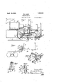
- FIG. 1 is a side elevation of aporltioniof a hopper car showing my invention :in position thereon, with parts broken away and parts in section, with :the brake operating mechanism in brake setting position;
- Fig. 2 is a diagrammatic view of a truck and brake mechanism
- Fig. Si a view similar to Fig. 1, showing the mechanism in brake releasing position;
- Fig. 4 is a horizontal section on line oiFig3; i
- FIG. 5 is a section on line 5- 5 of Fig. 3;
- Fig. 6 is a perspective" view of the j.aw member
- Fig. .7 is a perspective view Oflthe yoke member; v and I 8 is a perspective view of the multiplying lever.
- the present invention contemplates a construction in which :the power operating mechanism is operating mechbraake' rod 1 the limited space available he unineumbered in its operation by the hand operated'attachment.
- the numeral 1'0 designates 'a' railway ar-J1 the inclined bottom wall of the hopper-portion of the car, and 12 the cylinder lever which is pivoted to the bracket- 13 secured to'the upper portion of said wall.
- ⁇ Che brake cylinder is shown at let and'its push rod 15 is operatively connected to the lever 12 as by means of the pin and slot connection 16, the slot permitting a relative vertical movement of the lever due to its oscillation.
- the lever 12 is so mounted that it may swing from the full line position shown in Fig. :3 through the dotted line position shown in said figure into engagement with the cross member 60. While' the brake shoes are new the lever will move but a short distance'past'the dotted line position shown in said figure but as they become worn, the lever will move nearer and nearer to the transverse member 60. In any event, the'angular niovemen t of the lever 12 will be comparatively small so that in the application of the brakes, the line of movement of the push rod isabout normal to said lever iv-hereby the maximum lever efi'ect is obtained in setting thebrakes.
- Abrakerod 17 is connected atone end to the-brake lever 211 01 at its other end to the lower endofthe cylinder lever 12'whereby when the push rod15 is forced outward, the I 7 will be movedto apply the bra-kc shoes 30 to the'w heels in the usual manner. i i It is desirable that neansbeprovided for o. erating the brakes independently by hand.
- the hand ope rated 'n'iec hanism is c onnectedto, the brake lever for operating the same and ⁇ comprises the usual brakestaii ,18 and s 1 iral w-inding dr-nm 19.
- An expansible contraqtible connection is provided-between-the brake staff I8 and llever '12.
- As showmfthis connection comprises what for convenience "of description ⁇ will be termed-a multiplying lever 9 having the two arms-20 and 21', and rotatably mounted in a jaw member 22.
- the arm 20 will be termed the staff arm and the arm 21 the anchor arm. These arms are preferably rigidly connect-ed together and are rotatably mounted in what will be termed, the inner end of the jaw member 22.
- the jaw member 22 comprises the two side members 23 and. 24: which may be united by the connector member 25 and by the,
- arched member 26 The member 26 is arched to permit the rotation of the lever 9. It is provided with laterally and downwardly extending lugs 27 and 28 for engaging the inclined supporting bars 29 and 31 which are rigidly secured to the under-framing of the car and which are adapted to support the multiplying lever.
- the front end of the jaw member 22 is supported from the lever 12 in such manner that the lever 12 may be moved to brake applying position by the push rod 15 with out affecting the manually operated multiplying lever. As shown, this is accomplished by providing a hanger or yoke member 32 which straddles the lever 12 and is pivoted to the same as at 33.
- the yoke member is provided at each side thereof with outwardly extending alined trunnions 34 which are adapted to be pivoted to the ends 35 and 36 of the members 23 and 24 of the aw 22, see
- the trunnions 34 may be provided with heads permanently connected to the yoke member.
- the outer ends of the jaw member are slotted, and after they are slid on to the trunnions 34:, blocks 37, see Figs. 1 and 3, are inserted in the outer ends of the slots and rigidly secured therein by suitable means as the rivets or bolts 38.
- the staff arm 20 of the multiplying lever is preferably though not necessarily in the form of a segment having a comparatively long radius and provided with a substantially radial leading face all which merges into a drum surface 42 of comparatively short radius.
- the segment, face and drum are provided with a groove l3 for receiving the staff chain 44 which is secured at one end to the spiral drum 19, and its other end extends about the drum fl-2 and segmental arm 20 and is secured to said arm as at 4.5.
- the arm 21 merges into a grooved drum sur face 16 having a radius shorter than said arm.
- An anchor chain 50 hasone end secured to said arm, and has its opposite end adjustably secured to an anchor member 47.
- the arm 21 is arranged atan angle to the leading face 41 of the arm 20 whereby during the initial movement of the multiplying lever the staff cable will be operating on what may be'termed the short arm of the lever, and the anchor cable on the long arm of the lever, and vice versa during the final movement of the brake operating mechanism.
- the anchor member 47 comprises a plate 48 for securing the anchor to the underframing of the 'car. Rigidly mounted on the plate 48 is a vertically arranged sleeve 1-9 having the lower portion of its wall provided with open slots 51 and 52 for receiving a link of the chain or cable 50 which is threaded through said sleeve.
- the slot 51 is longer than the slot but the difference in length is less than the length of one of the links whereby a fine adjustment in the effective length of chain or cable 50 may be effected.
- the axle 53 on which the double lever 20, 21 is rotatably mounted, is extended at each end thereof in order that the same may engage the bars 29 and 31 should the aw member tend to raise during the application of the hand operated brake mechanism.
- the connecting portion 54 of the yoke 32 is adapted to engage the lever 12 and move the same in the direction of the brake staff when said staff is operated.
- the brake staff In applying the brakes by hand power, the brake staff is rotated whereupon the staff cable operating on the shorter radius of the drum 4-2 will rapidly rotate themultiplying lever, thus causing the arm 21 to take'up the slack very rapidly during the initial operation in applying the brakes.
- the cable 44 will be operating on the segment 20 of long radius and the anchor cable will be in engagement with the drum surface 46 and consequently the brakes may be set with powerful leverage.
- a brake mechanism for railway cars a brake staff, a brake lever, a contractible and expansible connection between said staff and lever comprising a cylinder lover,
- a brake operating mechanism for railway cars a brake staff, a brake lever, an eXpa-nsible and contractible connection between said staff and lever, said connection comprising a cylinder lever, a yoke pivotally connected to said cylinder lever, and a multiplying lever associated with'said yoke for operating said yoke and cylinder lever.
- a cylinder lever In a brake mechanism for railway cars, a cylinder lever, a yoke straddling said lever and pivoted thereto, a jaw member pivoted to said yoke, a multiplying lever journaled in said jaw member, a brake staff, an anchor member and a flexible member between said multiplying lever and said staff and anchor member.
- a hopper car having an inclined wall, a cylinder lever pivoted at its upper end, a brake lever, means for connecting the lower end of said cylinder lever to said brake lever, a push rod for operating said cylinder lever, an inclined guide, a jaw member slidably mounted on said guide, a multiplying lever journaled in one end of said jaw member, a yoke member straddling said cylinder lever and pivoted thereto, means for pivotally connecting said jaw member to said yoke member, a brakestaff, an anchor member, and flexible means between said multiplying lever and said staff and anchor.
- a brake operating mechanism for a hopper car comprising a cylinder lever pivoted at one end to said car, a brake rod connected to the opposite end of said lever, a push rod connected to said lever between said ends, a pair of inclined supporting rods, a jaw member slidably mounted on said rods, means for movably connecting said jaw to said lever, and expansible and contractable means hea brake staff, a brake lever,
- said means comprising a multiplying lever mounted rotatably in said jaw member.
- a brake lever power operated means including a cylinder lever for operating said brake lever, a brake staff and means for operatively connecting said staff and lever, said means including a multiplying lever and means for movably connecting said multiplying lever to said cylinder lever, whereby said cylinder lever may be operated without moving said ,multiplying lever.
- a cylinder lever pivoted to the inclined wall of said car, a brake rod pivoted to said lever,-a push rod for operating said lever, a yoke pivoted to said lever and straddling the same, inclined supporting members, a jaw member slidably mounted on said inclined members and pivotally connected to said yoke member, a multiplying lever pivoted in said yoke member, said multiplying lever comprising a staff arm and an anchor arm, each merging into a drum surface of short radius, a brake staff, a cable secured to said staff and to said staff arm, and adapted to engage said drum surface during the initial movement in applying the brakes, an anchormember and a cable adj ustably secured to said anchor member and having its opposite end secured to said anchor arm and adapted to engage the drum of said arm during the final movement in applying the brakes.
- a jaw member'for a railway brake operating mechanism comprising a pair of members, an arched brace connected to said members and outwardly and downwardly extending supports rigidly connected to said members, each end of said members being formed to engage journal members.
- An attachment for railway brake mechanism comprising a yoke member adapted to be pivoted to a cylinder lever, a jaw member pivoted to said yoke member, and a multiplying lever pivoted in said jaw member.
Landscapes
- Engineering & Computer Science (AREA)
- Mechanical Engineering (AREA)
- Braking Arrangements (AREA)
Description
April 19, 19 27. 7 1,624,924
P. B. CAMP BRAKE rmcmmxsm File d Aug. e. 1926 2 sheets-sheet i Patented Apr. 19, 1927.
PERCY 3. camp,
' ATTACHMENT 0 A ILLINOIS, ass enl a 1 9 vm msat 193mm ease .oom onarion or I moIs.
'BBMFE Application filed August 6, 1926 Serial 119. 127,572
is the power which power operating mechanism may be employed iin-' dependently of the hand anism.
A still further objectot the invention is the provision of a new and improved brake operating mechanism that is simple and rugged in construction, efficient in operation, composed of few moving. parts, and that is not likely. to become broken or get out of order.
(Ether and further objects and advantages of the invention'will appearffroin the 01- lowing description taken in connection with the accompanying drawings, in which- Fig. 1 is a side elevation of aporltioniof a hopper car showing my invention :in position thereon, with parts broken away and parts in section, with :the brake operating mechanism in brake setting position;
Fig. 2 is a diagrammatic view of a truck and brake mechanism; V
Fig. Sis a view similar to Fig. 1, showing the mechanism in brake releasing position;
Fig. 4 is a horizontal section on line oiFig3; i
5 is a section on line 5- 5 of Fig. 3;
Fig. 6 is a perspective" view of the j.aw member;
Fig. .7 is a perspective view Oflthe yoke member; v and I 8 is a perspective view of the multiplying lever.
p-Owing to neath hopper cars it .rlS extremely difficult to arrange brake operating mechanism heneath the sameso-that it may he operated either bypower or by hand. The present invention contemplates a construction in which :the power operating mechanism is operating mechbraake' rod 1 the limited space available he unineumbered in its operation by the hand operated'attachment.
Reference now being had to the draw ings in which the same reference characters designate the same parts throughout the drawings, the numeral 1'0 designates 'a' railway ar-J1 the inclined bottom wall of the hopper-portion of the car, and 12 the cylinder lever which is pivoted to the bracket- 13 secured to'the upper portion of said wall. {Che brake cylinder is shown at let and'its push rod 15 is operatively connected to the lever 12 as by means of the pin and slot connection 16, the slot permitting a relative vertical movement of the lever due to its oscillation.
The lever 12 is so mounted that it may swing from the full line position shown in Fig. :3 through the dotted line position shown in said figure into engagement with the cross member 60. While' the brake shoes are new the lever will move but a short distance'past'the dotted line position shown in said figure but as they become worn, the lever will move nearer and nearer to the transverse member 60. In any event, the'angular niovemen t of the lever 12 will be comparatively small so that in the application of the brakes, the line of movement of the push rod isabout normal to said lever iv-hereby the maximum lever efi'ect is obtained in setting thebrakes.
Abrakerod 17 is connected atone end to the-brake lever 211 01 at its other end to the lower endofthe cylinder lever 12'whereby when the push rod15 is forced outward, the I 7 will be movedto apply the bra-kc shoes 30 to the'w heels in the usual manner. i i It is desirable that neansbeprovided for o. erating the brakes independently by hand. in the :torm of' the device selected 'to illus crate one enrbodimentlof the invention the hand ope rated 'n'iec hanism is c onnectedto, the brake lever for operating the same and {comprises the usual brakestaii ,18 and s 1 iral w-inding dr-nm 19. An expansible contraqtible connection is provided-between-the brake staff I8 and llever '12. As showmfthis connection comprises what for convenience "of description {will be termed-a multiplying lever 9 having the two arms-20 and 21', and rotatably mounted in a jaw member 22. The arm 20 will be termed the staff arm and the arm 21 the anchor arm. These arms are preferably rigidly connect-ed together and are rotatably mounted in what will be termed, the inner end of the jaw member 22.
The jaw member 22 comprises the two side members 23 and. 24: which may be united by the connector member 25 and by the,
The front end of the jaw member 22 is supported from the lever 12 in such manner that the lever 12 may be moved to brake applying position by the push rod 15 with out affecting the manually operated multiplying lever. As shown, this is accomplished by providing a hanger or yoke member 32 which straddles the lever 12 and is pivoted to the same as at 33. The yoke member is provided at each side thereof with outwardly extending alined trunnions 34 which are adapted to be pivoted to the ends 35 and 36 of the members 23 and 24 of the aw 22, see
Figs. 1 and 6. For convenience of assembly,
and in order to permanently hold the parts assembled, and to avoid the use of detachable members in connecting the parts which would likely become accidentally detached and lost, the trunnions 34 may be provided with heads permanently connected to the yoke member. In order to do this, the outer ends of the jaw member are slotted, and after they are slid on to the trunnions 34:, blocks 37, see Figs. 1 and 3, are inserted in the outer ends of the slots and rigidly secured therein by suitable means as the rivets or bolts 38.
The staff arm 20 of the multiplying lever is preferably though not necessarily in the form of a segment having a comparatively long radius and provided with a substantially radial leading face all which merges into a drum surface 42 of comparatively short radius. The segment, face and drum are provided with a groove l3 for receiving the staff chain 44 which is secured at one end to the spiral drum 19, and its other end extends about the drum fl-2 and segmental arm 20 and is secured to said arm as at 4.5. The arm 21 merges into a grooved drum sur face 16 having a radius shorter than said arm. An anchor chain 50 hasone end secured to said arm, and has its opposite end adjustably secured to an anchor member 47.
The arm 21 is arranged atan angle to the leading face 41 of the arm 20 whereby during the initial movement of the multiplying lever the staff cable will be operating on what may be'termed the short arm of the lever, and the anchor cable on the long arm of the lever, and vice versa during the final movement of the brake operating mechanism.
The anchor member 47 comprises a plate 48 for securing the anchor to the underframing of the 'car. Rigidly mounted on the plate 48 is a vertically arranged sleeve 1-9 having the lower portion of its wall provided with open slots 51 and 52 for receiving a link of the chain or cable 50 which is threaded through said sleeve. The slot 51 is longer than the slot but the difference in length is less than the length of one of the links whereby a fine adjustment in the effective length of chain or cable 50 may be effected.
By providing the two levers 20 and 21 and so arranging them that one of the cables will be disposed along one side of the lever 12 and the other on the other side of said lever, there will be no tendency of the jaw member to rotate horizontally, which would probably be the case were a single reversible lever employed with both cables on the same side of the lever 12.
The axle 53 on which the double lever 20, 21 is rotatably mounted, is extended at each end thereof in order that the same may engage the bars 29 and 31 should the aw member tend to raise during the application of the hand operated brake mechanism.
The connecting portion 54 of the yoke 32 is adapted to engage the lever 12 and move the same in the direction of the brake staff when said staff is operated.
In the operation of the brake by power, the lever 12 is forced forwardly by the push rod 15, the hanger or yoke 32 being pivoted at '33 will swing counter clockwise until the pivots 33, 34 and 53 come into alinement, without otherwise affecting the hand operated mechanism. \Vhen the brake shoes are released the weight of the yoke member and the hand operated mechanism will tend to assist the brake releasing movement of the lever 12 and will tend to hold the brake shoes out of contact with the wheels.
In applying the brakes by hand power, the brake staff is rotated whereupon the staff cable operating on the shorter radius of the drum 4-2 will rapidly rotate themultiplying lever, thus causing the arm 21 to take'up the slack very rapidly during the initial operation in applying the brakes. During the final movement in setting the brakes, the cable 44 will be operating on the segment 20 of long radius and the anchor cable will be in engagement with the drum surface 46 and consequently the brakes may be set with powerful leverage.
lVhen the brakes are released, the multi plying lever and associated parts will be caused to slide downward along the rods 29 and 31 by the vibration incident to the movement of the car.
I claim as my invention:
1. In a brake mechanism for railway cars, a brake staff, a brake lever, a contractible and expansible connection between said staff and lever comprising a cylinder lover,
a multiplying lever, and means for movably connecting said multiplying lever to said cylinder lever. 1
2. In a brake operating mechanism for railway cars, a brake staff, a brake lever, an eXpa-nsible and contractible connection between said staff and lever, said connection comprising a cylinder lever, a yoke pivotally connected to said cylinder lever, and a multiplying lever associated with'said yoke for operating said yoke and cylinder lever.
3. In a brake mechanism for railway cars, a cylinder lever, a yoke straddling said lever and pivoted thereto, a jaw member pivoted to said yoke, a multiplying lever journaled in said jaw member, a brake staff, an anchor member and a flexible member between said multiplying lever and said staff and anchor member.
4:. In combination, a hopper car having an inclined wall, a cylinder lever pivoted at its upper end, a brake lever, means for connecting the lower end of said cylinder lever to said brake lever, a push rod for operating said cylinder lever, an inclined guide, a jaw member slidably mounted on said guide, a multiplying lever journaled in one end of said jaw member, a yoke member straddling said cylinder lever and pivoted thereto, means for pivotally connecting said jaw member to said yoke member, a brakestaff, an anchor member, and flexible means between said multiplying lever and said staff and anchor.
5. A brake operating mechanism for a hopper car comprising a cylinder lever pivoted at one end to said car, a brake rod connected to the opposite end of said lever, a push rod connected to said lever between said ends, a pair of inclined supporting rods, a jaw member slidably mounted on said rods, means for movably connecting said jaw to said lever, and expansible and contractable means hea brake staff, a brake lever,
tween said brake staff and brakelever, said means comprising a multiplying lever mounted rotatably in said jaw member.
6. In a brake operating mechanism for railway cars, a brake lever, power operated means including a cylinder lever for operating said brake lever, a brake staff and means for operatively connecting said staff and lever, said means including a multiplying lever and means for movably connecting said multiplying lever to said cylinder lever, whereby said cylinder lever may be operated without moving said ,multiplying lever.
7. In a railway brake operating mechanism for a hopper car, a cylinder lever pivoted to the inclined wall of said car, a brake rod pivoted to said lever,-a push rod for operating said lever, a yoke pivoted to said lever and straddling the same, inclined supporting members, a jaw member slidably mounted on said inclined members and pivotally connected to said yoke member, a multiplying lever pivoted in said yoke member, said multiplying lever comprising a staff arm and an anchor arm, each merging into a drum surface of short radius, a brake staff, a cable secured to said staff and to said staff arm, and adapted to engage said drum surface during the initial movement in applying the brakes, an anchormember and a cable adj ustably secured to said anchor member and having its opposite end secured to said anchor arm and adapted to engage the drum of said arm during the final movement in applying the brakes.
8. A jaw member'for a railway brake operating mechanism comprising a pair of members, an arched brace connected to said members and outwardly and downwardly extending supports rigidly connected to said members, each end of said members being formed to engage journal members.
9. An attachment for railway brake mechanism comprising a yoke member adapted to be pivoted to a cylinder lever, a jaw member pivoted to said yoke member, and a multiplying lever pivoted in said jaw member.
In testimony whereof I affix my signature.
PERCY B. CAMP.
Priority Applications (1)
| Application Number | Priority Date | Filing Date | Title |
|---|---|---|---|
| US127572A US1624924A (en) | 1926-08-06 | 1926-08-06 | Brake mechanism |
Applications Claiming Priority (1)
| Application Number | Priority Date | Filing Date | Title |
|---|---|---|---|
| US127572A US1624924A (en) | 1926-08-06 | 1926-08-06 | Brake mechanism |
Publications (1)
| Publication Number | Publication Date |
|---|---|
| US1624924A true US1624924A (en) | 1927-04-19 |
Family
ID=22430788
Family Applications (1)
| Application Number | Title | Priority Date | Filing Date |
|---|---|---|---|
| US127572A Expired - Lifetime US1624924A (en) | 1926-08-06 | 1926-08-06 | Brake mechanism |
Country Status (1)
| Country | Link |
|---|---|
| US (1) | US1624924A (en) |
-
1926
- 1926-08-06 US US127572A patent/US1624924A/en not_active Expired - Lifetime
Similar Documents
| Publication | Publication Date | Title |
|---|---|---|
| US2253824A (en) | Caster for application to vehicles | |
| US1624924A (en) | Brake mechanism | |
| US1964138A (en) | Brake slack adjuster | |
| US3298475A (en) | Brake mechanism | |
| US2191138A (en) | Clasp brake | |
| US1623227A (en) | Brake mechanism | |
| US2083910A (en) | Unit cylinder drum brake | |
| US1201684A (en) | Vehicle-brake. | |
| US1494976A (en) | Safety brake | |
| US1752704A (en) | Railway brake equipment | |
| US833076A (en) | Brake. | |
| US302651A (en) | conway | |
| US1726015A (en) | Brake mechanism | |
| US441015A (en) | Automatic car-brake | |
| US1603745A (en) | Brake mechanism for railway cars | |
| US737713A (en) | Brake-rigging. | |
| US412747A (en) | hawes | |
| US1820856A (en) | Brake rigging for railway cars | |
| US384870A (en) | John h | |
| US1978264A (en) | Seesaw | |
| US1421697A (en) | Brake release spring mechanism for tram and the like cars | |
| US1037090A (en) | Brake-rigging. | |
| US1726005A (en) | Sled brake | |
| US1795954A (en) | Hand-brake mechanism | |
| US695274A (en) | Means for providing brakes to railway-vehicles. |