US1619703A - Power-transmission mechanism - Google Patents
Power-transmission mechanism Download PDFInfo
- Publication number
- US1619703A US1619703A US752748A US75274824A US1619703A US 1619703 A US1619703 A US 1619703A US 752748 A US752748 A US 752748A US 75274824 A US75274824 A US 75274824A US 1619703 A US1619703 A US 1619703A
- Authority
- US
- United States
- Prior art keywords
- torque
- clutches
- members
- driving
- valve
- Prior art date
- Legal status (The legal status is an assumption and is not a legal conclusion. Google has not performed a legal analysis and makes no representation as to the accuracy of the status listed.)
- Expired - Lifetime
Links
- 230000007246 mechanism Effects 0.000 title description 48
- 239000012530 fluid Substances 0.000 description 46
- 230000005540 biological transmission Effects 0.000 description 28
- 230000001276 controlling effect Effects 0.000 description 15
- 238000010276 construction Methods 0.000 description 11
- 230000000670 limiting effect Effects 0.000 description 9
- 230000002441 reversible effect Effects 0.000 description 4
- 230000001419 dependent effect Effects 0.000 description 3
- 230000000694 effects Effects 0.000 description 3
- 230000036961 partial effect Effects 0.000 description 3
- RTZKZFJDLAIYFH-UHFFFAOYSA-N Diethyl ether Chemical compound CCOCC RTZKZFJDLAIYFH-UHFFFAOYSA-N 0.000 description 2
- 238000002485 combustion reaction Methods 0.000 description 2
- 230000003137 locomotive effect Effects 0.000 description 2
- 241000182988 Assa Species 0.000 description 1
- 240000008881 Oenanthe javanica Species 0.000 description 1
- 230000032683 aging Effects 0.000 description 1
- 230000003247 decreasing effect Effects 0.000 description 1
- 238000000034 method Methods 0.000 description 1
- 230000007935 neutral effect Effects 0.000 description 1
- 229920000136 polysorbate Polymers 0.000 description 1
- 230000000750 progressive effect Effects 0.000 description 1
- 230000002829 reductive effect Effects 0.000 description 1
- 230000001105 regulatory effect Effects 0.000 description 1
- 230000000630 rising effect Effects 0.000 description 1
- 235000002020 sage Nutrition 0.000 description 1
- 230000013707 sensory perception of sound Effects 0.000 description 1
- 230000035939 shock Effects 0.000 description 1
- 230000035882 stress Effects 0.000 description 1
Images


Classifications
-
- F—MECHANICAL ENGINEERING; LIGHTING; HEATING; WEAPONS; BLASTING
- F16—ENGINEERING ELEMENTS AND UNITS; GENERAL MEASURES FOR PRODUCING AND MAINTAINING EFFECTIVE FUNCTIONING OF MACHINES OR INSTALLATIONS; THERMAL INSULATION IN GENERAL
- F16H—GEARING
- F16H61/00—Control functions within control units of change-speed- or reversing-gearings for conveying rotary motion ; Control of exclusively fluid gearing, friction gearing, gearings with endless flexible members or other particular types of gearing
- F16H61/02—Control functions within control units of change-speed- or reversing-gearings for conveying rotary motion ; Control of exclusively fluid gearing, friction gearing, gearings with endless flexible members or other particular types of gearing characterised by the signals used
- F16H61/0262—Control functions within control units of change-speed- or reversing-gearings for conveying rotary motion ; Control of exclusively fluid gearing, friction gearing, gearings with endless flexible members or other particular types of gearing characterised by the signals used the signals being hydraulic
-
- F—MECHANICAL ENGINEERING; LIGHTING; HEATING; WEAPONS; BLASTING
- F16—ENGINEERING ELEMENTS AND UNITS; GENERAL MEASURES FOR PRODUCING AND MAINTAINING EFFECTIVE FUNCTIONING OF MACHINES OR INSTALLATIONS; THERMAL INSULATION IN GENERAL
- F16H—GEARING
- F16H2718/00—Mechanisms for speed-change of planetary gearing, the speed change control being dependent on function parameters of the gearing
- F16H2718/18—Control dependent on torque
- F16H2718/20—Control dependent on torque only the toothed wheels remain engaged
- F16H2718/24—Control dependent on torque only the toothed wheels remain engaged the control being hydraulic or pneumatic
Definitions
- This invention relates to mechanical power transmission systems and has for its primary object to protect such a system from undue stresses due for example to overloads or sudden shocks.
- the invention is more especially intended for use on an 1ov internal combustion engine locomotive for the pur ose of preventing stalling or straining of t e engine.
- a torque limiting device is connected to one member of,
- the transmission mechanism in such a manner as to be operated by variations in the torque transmitted through this member, the demos acting to control a variable driving connection in the transmission system, as for example by effecting the disengagement of a clutch mechanism when the torque exceeds a predetermined limit.
- the invention may be applied to a transmission system which includes an e icyclic variable speed gear of the kind e scribed in the present applicants prior United States of America patent application Seri al No. 724,719 in which the speed changes are brought about by means of slipping clutches of the late type preferably controlled selectively y a uid pressure system.
- the to no limiting device may act to control the uid pressure in the system and thus also the ogeration of the plate clutches.
- a further 0 ject of the invention is to provide a convenient mechanical construction for a torque limiting device, which is operative in accordance with torque variations, preferably irrespective of the speed of the member to which the device is connected.
- Another object of the invention is to provide means for progressively varying the effect of the torque limiting device in accordance with torque variations.
- a further object is to prevent damage occuring when a reversal of the torque takes place and the driven member of the system drives the drivin member.
- FIG. 1 is a. longitudinal section showing one form of torque limiting device to ether with a convenient construction of eplcyclic variable speed gear.
- Figures 2 and 3 are cross-sections on an enlarged scale on the line 2-2 of Figure 1 and show two alternative arrangements of relief passages.
- Figure 4 1 s an end view of an alternative construction of torque limiting device taken princlpallyon line 4-4 of Fig. 5,
- F1gure 5 is a. section on the line 5-5 of F1 re 4, and
- Figs. 6 shows the alternative construction of Figs. 4 and 5 in association with a variable speed gear
- I y 75 F Figfi. 7 is an elevation of a portion of n'the construction illustrated in Figure l the variable speed gear com rises a driving member A and a driven mem r B, the driv- 1ng member A being connected to a driving shaft A by means of a torque limiting device C.
- the members A and B are supported in hearings in a frame D and the member B carries at one end a bevel pinion B while its other end is connected to a member B on which are mounted the planet pinions B of the epicyclic gear.
- rotatably mounted outside the member B is a member F carr ing the toothed annulus F of the epic c is gear.
- Four plate clutches are provided a clutch 1 adapted to connect the annulus F to the frame D and thus hold the annulus stationary, a clutch 2 adapted to connect the driving member A to the member F carrying the annulus F, a clutch 3 adaptedto connect the driving member A to the sleeve E carrying 100 the sun pinion E and a. clutch 4 adapted to connect the sleeve E carrying the sun pinion E to a stationary part G of the mechanism.
- Each of the clutches 1, 2, 3 and 4 is adapted to be controlled by a series of plunger devices 1 H arranged in the end of the clutch casing.
- Each of these plunger devices is formed as a piston working within a cylinder H adapted to press on the end clutch plate so as to cause the engagement of the clutch.
- a cylinder H has o ning's H it which comuid chamber. in the'. clutch member G each have 'a'hollow bore within which is mounted to slide a valve member K, this valve member passing through the interior of the member E and beingadapted to control the flow of fluid through passages L, L, L, and L leadin respectively to the chambers J, J J and and also the flow of fluid from these chambers to relief passages L", L formed respectively in the members A and B.
- the valve member K is the valve member K, this valve member passing through the interior of the member E and beingadapted to control the flow of fluid through passages L, L, L, and L leadin respectively to the chambers J, J J and and also the flow of fluid from these chambers to relief passages L", L formed respectively in the members A and B.
- a ressure regulating device comprising a fixed piston M and a movable cylinder M fittin over it, the fluid being admitted to the cy inder through an internal assage in the piston. Means are provided hereby when the cylinder is raised beyond a predetermined limit the inlet valve M of the pump M is opened to prevent further delivery from the ump until the pressure has fallen suflicient y to enable the valve M again to close.
- the ports and recesses in the valve member K are so shaped and disposed that when the valve is in the position shown all the passages L, L, L and'L are in communication with the relief passages L and L so that all the clutches are disengaged and the gear interior of is thus in its neutral position.
- the valve member K ismoved to the position K the passages L and L remain in communication with the relief passages while the passages L and L are cut off from relief and are placed in communication with the the valve member K'so that fluid under pressure passes to these passages and thus causes the'engagement of the clutches 1 and 3.
- the torque limiting device is however adapted to open a relief passa e N and thus relieve the fluid pressure witl iin the member K so as to bring about the disengagement of all the clutches, if and when the torque transmitted through the driving member A exceeds a predetermined limit and preferably also if the member B tends to drive the member A and the reverse torque thus produced exceeds a predetermined limit.
- the torque limiting device C comprises two coaxial wheels C C which are mounted respectively on the driving shaft A and the driving member A and are connected together. by a series of springs C
- the actual arrangement of the springs C is similar to that shown in the alternative construction illustrated in Figures 4 and 5 to be described later. It will be seen that with this arrangement variations in the torque transmitted through the member C will cause relative rotation between the wheels C and C
- the driving shaft A -which is connected to the wheel C of the device C is provided with an annular extension A which is in the form of a ported sleevearranged as shown in section in Figure 2 or in Figure 3 so as to establish communication under certain conditions between the passage N and a recess N in the hub of the wheel C.
- the recess N is in constant communication with a. pas sage L leading into the relief passage L. 3
- the sleeve A is provided with two ports N and N the direction of rotation being indicated by the arrow.
- An increase in torque causes the wheel C to move relatively to the wheel C in the direction of the arrow, and if the torque increases beyond a predetermined. maximum, the relative move;
- FIG. 3 The construction shown in Figure 3 is similar to that shown in Fi re 2 except that, in addition to the ports F and N further ports N, N 5 and N are provided in the sleeve A so as to register with the passa e N at various relative positions of the whee C and C
- the port N is adapted to register with the passage N when the wheels C and C are in their no-torque position, this port being of such cross section that it perressure
- a certain amount of fluid pressure'ls admitted to the operating mechanism of the clutches in question th1s fluid pressure being su'flicient to cause a partial engagement of such clutches a certain amount of slipping being allowed to occur between the separate plates of the clutches;
- This partial engagement allows a relatively small mount of torque to be transmitted through the device C and this torque in turn causes-a small amount of relative rotation between the wheels C and C sufficat-ion with e port N.
- the port N is of 1 smaller cross section than the port N so that the amount of fluid relief is reduced and the clutches are engaged somewhat more tightly.
- This further engagement allows still further torque to be transmitted through the device C and the consequent further relative rotation brings the passage N intocommunication with the port N which is still more restricted than the. port N.
- the degree of engagement of the plates of the clutch is thus still further increased with a corresponding increase in the torque transmitted through the. device C, until finally the passage N moves out of engagement with the port N and the clutches are subjected to the full fluid pressure. It will be seen that, with this arrangement the gradual progressive engagement of the clutches is en-' sured and further the disengagement of the side of the gear.
- Figures 4 and 5 show an alternative construction of the device which can be disposed at any convenient point in the transmission s stem either on the drivin side or on the riven
- the device controls a relief valve 0 controlling a relief passage 0 which is connected to a convenient-point in the fluid pressure system controlling the gear, as for example to the main supply passage (indicated at L in Figure 1).
- the device comprises two coaxial Wheels P P which are connected together by s rings P and are mounted respectively on t e two parts P P of a shaft forming part of the transmission system, the part P being on the driving side.
- a set of planet pinions Q mounted on spindles Q journalled on the wheel P, whilst the member P carries a similar set of spindles R on which are mounted planet pinions R. Both these sets of planet pinions mesh with a common sun pinion S mounted to rotate freely on a boss P on the shaft P.
- a toothed annulus T meshes with the pinions Q and is carried by a fixed bracket U.
- a second toothed annulus T meshes with the pinions and is carried by an arm V connected at its outer end by means of a link V to one arm of a lever V pivoted at V, the other arm of this lever V? acting on the valve 0.
- the arm V carries a pin V which passes through an arcuate slot in the fixed bracket U.
- the valve 0 is preferably provided with a series of relief ports 0 O, O, O and O, which correspond to the.ports N N 'N, N and N in the construction illustrated in Figure 3.
- the pressure will be relieved to a progressively decreasing extent as the wheels P P beginvto move relatively from the zero position, until the normal running position isreached when the ports 0, O 0 will have moved past the passage 0 and this passage will be closed.
- the port In the event of'an increase in torque beyond the predetermined limit the port will 0 en. the passage 0' and completely relieve t e pressure in the system. Similarly, if a reversal of the torque takes place and there is a tendency for the shaft P to drive the shaft P, the pressure will be relieved through the port 0 when the reverse torque exceeds a predetermined limit.
- Figure 6 shows the manner in which the torque-responsive device of Figures 4 and 5 can be used to control the supply of ressure fluid to a variable speed ear 0 the kind shown in Figure 1.
- the gear is identical with that shown in Figure 1 and the same reference letters are emthe left-hand side of the ployed, the fluid supply apparatus M M eing shown on gear for convenience.
- the torque-respon sive device in Figure 6 is identical with that shown in Figure 5 and the same reference letters are employed, the valve 0 0 (shown in Figure 4) being included on a smaller scale.
- the relief passage 0 controlled by this valve is connected to the main fluid supply passage L.
- a driving member a driven member
- a clutch mechanism adapted when engaged to bring into eflect a driving connection between these two members
- a fluid pressure system for eflecting the engagement and disengagement of the clutch mechanism
- a device through which the power is transmitted comprising flexibly connected driving and'driven parts so arranged that relative movement is produced between these two parts by variations in the torque transmitted through them irrespective of their speed, and means whereby such relative movement beyond a predetermined limit acts I on the fluid pressure system so as to cause disengagement of the clutch mechanism.
- a power transmission mechanism In a power transmission mechanism the combination of a driving member, a driven member, a variable speed gear connecting these members, clutches for bringing the various gear ratios into operation, a fluid pressure system for selectively controlling the clutches, a device connected to one of the members comprising two flexibly connected parts between which relative movement is produced by variations in t e torque transmitted through the member to which the device is connected, and means whereby such relative movement beyond a predetermined limit acts on the fluid pressure systemso as to cause the disengagement of at least one of the clutches.
- a power transmission mechanism the combination of a driving member, a driven member, an epicyclic variable speed gear connecting these members, plate clutches for bringing the various gear ratios into operation, a fluid pressure system for selectlvely controlling the plate clutches, a device through which the power is transmitted comprising two flexibly connected parts so arranged that relative movement is produced between these two parts by variations in the torque transmitted through them,
- yond a predetermined limit acts to relieve the pressure in the fluid pressure system and thereby to release all the plate clutches.
- a driving member a driven member, one of these members being divided into two parts, a variable driving connection between the two members, a device forming an operative connection between. the two parts ofthe divided member and comprisand means whereby such relative movement bewheels, diflerential mechanism operated inaccordance with the relative movement between the two wheels, and means whereby such relative movement beyond a predetermined limit causes the differential mechanism to act on the fluid pressure system and thereby to disengage the clutch mechanism.
- a driving member In a power transmission mechamsm the combination of a driving member, a driven member, one of these members being divided into two parts, a variable speed gear interposed between the two members, clutches controlling the speed changes of the variable speed gear, a device forming an o erative connection between the two parts 0 the divid'ed member and com rising two coaxial wheels carried respective y by the two parts and a resilient connection between the two wheels, differential mechanism operated in accordance with the relative movement between these two wheels, and means where by such relative movement beyond a predetermined limit causes the diflerential mechanism to disengage at least one of the clutches;
- a driving member a driven member, one of these members being divided into two parts, an epicyclic variable s eed gear inter osed between the two mem ers, plate clutc es controlling the speed changes of the variable speed gear, a fluid pressure system for selectively engaging and disengaging the plate clutches, a device forming an operative connection between the two parts of the divided member and comprising two coaxial wheels carried respectively by these two parts and a spring connection between the two wheels, diflerential mechanism operated in accordance with the relative movement between the two wheels, and means whereby such relative movement beyond a predetermined limit causes the differential mechanism to relieve thepressure in the fluid pressure 5 stem and thereby to release the plate clutc es.
- variable driving connection between the two members, two coaxial wheels carried respectively by the two parts of the driving member, a resilient connection between the two wheels, two sets of planet pinions carried respectively by the two wheels, a common sun pinion with which an the planet pinions engage, two toothed annuli engaging respectivel with the two sets of planet pinions one o the annuli being held stationary, and means whereby movement of the second annulus is caused to control the variable driving connection.
- a driving shaft a driven member, an intermediate shaft, a clutch mechanism interposed between the intermediate shaft and the driven member, a fluid pressure system for controlling the clutch mechanism, two coaxial wheels carried respectively by the driving shaft and the in termediate shaft, a resilient connection between the two wheels, two sets of planet pinions carried respectively by the two wheels, a common sun PlIllOIl with which all the planet pinions engage, two toothed annuli engaging respectively with the two sets of planet pinions one of the annuli being held stat1onary, and means whereby movement of the second annulus is caused to act on the fluid pressure system and thereby to disengage the clutch mechanism.
- a power transmission mechanism the combination of a drivin member, a driven member, a variable driving connection between these members, fluid pressure operated mechanism for controlling the variabledrivin g connection, means for delivering fluid under pressure to this mechanism, a relief valve controlling the pressure of the fluid delivered and having a plurality of alternative relief assages so arranged that the pressure will be relieved to an extent dependent upon the travel of the valve, a device connected to one of the members comprising two flexibly connected parts between which relative movement is produced by variations in the torque transmitted through the member to which the device'is connected, and means whereby such relative movement is caused to operate the relief valve.
- a driving member a driven member, an epicyclic variable speed gear interposed between these members, plate clutches for bringing the various gear ratios into operation, fluid pressure operated mechanism for selectively controlling the plate clutches, means for delivering fluid under pressure to this mechamsm, a relief valve controlling the pressure of the fluid delivered and havin a plurality of relief passages s0 arranged t at the pressure will be relieved to an extent dependent upon the travel of the valve, a device connected to one of the members of the transmission mechanism comprising two flexibly connected parts between which relative movement is produced by variations in the torque transmitted through the memher to which the device is connected, an means whereby such relative movement is caused to. operate the reliefvalve in such a manner as to relieve the pressure to a varying extent as the torque increases and theretransmitted through the member to which takes mechanism,
- the device is connected, means whereby such relative movement is caused to control the variable driving connection and means for disconnecting the driven member from the driving member if a reversal of the torque lace and the driven member tends to drive t e driving member whereby the transmission of torque greater than a predetermined maximum from the driven member tothe driving member is rendered impossible.
- clutch mechanism adapted when engaged to brin into effect a driving connection between t ese two members, a device connected to one of the members comprising two flexibly connected parts relatively movement between which is produced by variations in the torque transmitted through the member to which the device is connected irrespective of the speed of this member, and means whereby such relative movement beyond a predetermined limit in either direction brings about the disenga ement of the clutch mechanism and there y renders impossible the transmission of torque greater than a predetermined maximum from one of the members to the other.
- a driving member a driven member
- a clutch mechanism adapted when engaged to brin ,into effect a driving connectlon between t ese two members
- a fluid pressure system for effecting the engagement and disengagement of the clutch a device through which the power is transmitted
- flexibly connected driving and driven parts so arranged that relative movement is produced between these two parts by variations in the torque transmitted through them irrespective of their speed means whereby such relative movement i limit acts on the fluid pressure system so as either direction.
- a driving member for bringing the various gear ratios into operation
- a fluid pressure system for selectively controlling the clutches
- a device connected to one of the members comprisin two flexibly connected parts between w 'ch relative movement is produced by variations in the torque transmitted through the member to which the device is connected, and means whereby such relative movement beyond a predetermined limit in either direction acts on the fluid pressure system so as to cause the disengagement of at least one of the clutches.
- a driving member a driven member, an e icyclic variable speed gear interposed tween these members, plate clutches for bringing the various gear ratios into operation, fluid pressure operated mechanism for selectively controlling the plate clutches, means for delivering fluid under pressure to this mechanism, a relief valve controlling the pressure of the fluid delivered and having a plurality of relief passages so arranged that the pressure will be relieved to an extent dependent upon the travel of the valve, a device connected to one of the members of the transmission mechanism comprising two flexibly connected parts between which relative movement is produced vby variations in the torque transmitted through the member to which the device is connected, and means whereby such relative movement is caused to operate the relief valve in such a manner as to relieve the pressure to a varying extent as the torque increases and thereby to allow a varying amount of slipping to occur between the so arate plates of the clutches and also to re ieve the pressure completely and thereby to bring about the disengagement of all the'clutches when the relative
Landscapes
- Engineering & Computer Science (AREA)
- General Engineering & Computer Science (AREA)
- Mechanical Engineering (AREA)
- Retarders (AREA)
Description
1 March 1 1927' A. E. L. CHQRIJTQN 703 POWER TRANSMISS I'QN MEC-HANI SM Filed Nov. 28.. 1924 4 Sheets-Sheet 1 E 7 dub M v W- a.
March 1927' A. E. 1.. CHORLTON A QVvVY 1 0 March 1927 A. E. L. CHORLTON POWER TRANSMISSION MECHANISM Filed NOV. 28,. 1924 4 Sheets-Sheet 5 are 7 A. E. L. CHORLTON POWER TRANSMISSION MECHANISM Fi 28, 1924 4 sheets sheet 4 IIYVEN 7'07? Patented Mar. 1 1927.
ALAN ERNESTHOFRIC CHOBL'ION, OI LEIIDON, ENGLAND.
rownwrnansmssron uncnmrsu.
Application m November 20, 1924. semi No. 752,748.
This invention relates to mechanical power transmission systems and has for its primary object to protect such a system from undue stresses due for example to overloads or sudden shocks.
Although generally applicable to mechanisms in which power is transmitted from-a prime mover to a variable load, the invention is more especially intended for use on an 1ov internal combustion engine locomotive for the pur ose of preventing stalling or straining of t e engine.
According to this invention a torque limiting device is connected to one member of,
the transmission mechanism in such a manner as to be operated by variations in the torque transmitted through this member, the demos acting to control a variable driving connection in the transmission system, as for example by effecting the disengagement of a clutch mechanism when the torque exceeds a predetermined limit.
Thus the invention may be applied to a transmission system which includes an e icyclic variable speed gear of the kind e scribed in the present applicants prior United States of America patent application Seri al No. 724,719 in which the speed changes are brought about by means of slipping clutches of the late type preferably controlled selectively y a uid pressure system. In this case the to no limiting device may act to control the uid pressure in the system and thus also the ogeration of the plate clutches.
A further 0 ject of the invention is to provide a convenient mechanical construction for a torque limiting device, which is operative in accordance with torque variations, preferably irrespective of the speed of the member to which the device is connected.
Another object of the invention is to provide means for progressively varying the effect of the torque limiting device in accordance with torque variations.
A further object is to prevent damage occuring when a reversal of the torque takes place and the driven member of the system drives the drivin member.
Still further objects ot the invention will be apparent from the "following descri tion of the accompanying drawings. These rawings illustrate by way of example two alternative methods of carrying out the invention, more particular] I in its application to a transmlsison mec inan internal com bustion engine locomotive employing an epicyhc gear of the kind described in the abovcmentioned prior application.
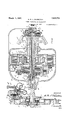
In these drawings-- Figure 1 is a. longitudinal section showing one form of torque limiting device to ether with a convenient construction of eplcyclic variable speed gear.
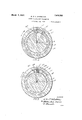
Figures 2 and 3 are cross-sections on an enlarged scale on the line 2-2 of Figure 1 and show two alternative arrangements of relief passages.
Figure 4 1s an end view of an alternative construction of torque limiting device taken princlpallyon line 4-4 of Fig. 5,
F1gure 5 is a. section on the line 5-5 of F1 re 4, and
ig. 6 shows the alternative construction of Figs. 4 and 5 in association with a variable speed gear; and I y 75 F Figfi. 7 is an elevation of a portion of n'the construction illustrated in Figure l the variable speed gear com rises a driving member A and a driven mem r B, the driv- 1ng member A being connected to a driving shaft A by means of a torque limiting device C. The members A and B are supported in hearings in a frame D and the member B carries at one end a bevel pinion B while its other end is connected to a member B on which are mounted the planet pinions B of the epicyclic gear. Rotatably mounted within the members A and B is a hollow sleeve E carrying the sun pinion E of the e icyclic gear, and rotatably mounted outside the member B is a member F carr ing the toothed annulus F of the epic c is gear. Four plate clutches are provided a clutch 1 adapted to connect the annulus F to the frame D and thus hold the annulus stationary, a clutch 2 adapted to connect the driving member A to the member F carrying the annulus F, a clutch 3 adaptedto connect the driving member A to the sleeve E carrying 100 the sun pinion E and a. clutch 4 adapted to connect the sleeve E carrying the sun pinion E to a stationary part G of the mechanism. Each of the clutches 1, 2, 3 and 4 is adapted to be controlled by a series of plunger devices 1 H arranged in the end of the clutch casing. Each of these plunger devices is formed as a piston working within a cylinder H adapted to press on the end clutch plate so as to cause the engagement of the clutch. The
I a cylinder H has o ning's H it which comuid chamber. in the'. clutch member G each have 'a'hollow bore within which is mounted to slide a valve member K, this valve member passing through the interior of the member E and beingadapted to control the flow of fluid through passages L, L, L, and L leadin respectively to the chambers J, J J and and also the flow of fluid from these chambers to relief passages L", L formed respectively in the members A and B. The valve member K. is hollow and fluid under pressure is constantly fed to the interior thereof through a passage L communicating'at one end through an annular recess L" with the interior of the member K and at the other end with a source of fluid pressure, the flow of fluid to and from the various passages L, L L and L being adapted to take place respectively through ports and recesses in the wall of the valve member K. The fluid is supplied from a reservoir M through an inlet valve M to a pump M and is delivered therefrom through a delivery valve M to the passage L. A ressure regulating device is provided comprising a fixed piston M and a movable cylinder M fittin over it, the fluid being admitted to the cy inder through an internal assage in the piston. Means are provided hereby when the cylinder is raised beyond a predetermined limit the inlet valve M of the pump M is opened to prevent further delivery from the ump until the pressure has fallen suflicient y to enable the valve M again to close.
The ports and recesses in the valve member K are so shaped and disposed that when the valve is in the position shown all the passages L, L, L and'L are in communication with the relief passages L and L so that all the clutches are disengaged and the gear interior of is thus in its neutral position. When the valve member K ismoved to the position K the passages L and L remain in communication with the relief passages while the passages L and L are cut off from relief and are placed in communication with the the valve member K'so that fluid under pressure passes to these passages and thus causes the'engagement of the clutches 1 and 3. This brings the first and lowest gear into operation, \in which the driving member A is clutched to the sun pinion E and drives the member B through the planet pinions, the annulus F being held stationary. When the valve member K is moved into the position K the passages L and L are opened to the relief passages so as to disengage the clutches 1 and 3 while the passages L and L are brought into communication with the interior of the valve clutches 2 and 4. In this position the second ear comes into operation, in which the drivin member A is clutched to the toothed annu as F and drives the member B through the lanet pinions B, the sun pinion E being eld stationary. In the position K the passages L and L are opened to the relief assa es while thepassages L and L are roug t into communication with the interior of the valve member K so that the clutches 1 and 4 are disen aged and the clutches 2 and 3 are engaged. In this position a direct drive is effected, the sun pmion E and the annulus F both being connected directly to the driving member A.
It will be seen that, as long as suflicient fluid pressure exists within the member K, those clutches to which pressure is supplied in accordance with the position of this member are held in close engagement, the remaining clutches bein disengaged. The torque limiting device is however adapted to open a relief passa e N and thus relieve the fluid pressure witl iin the member K so as to bring about the disengagement of all the clutches, if and when the torque transmitted through the driving member A exceeds a predetermined limit and preferably also if the member B tends to drive the member A and the reverse torque thus produced exceeds a predetermined limit.
The torque limiting device C comprises two coaxial wheels C C which are mounted respectively on the driving shaft A and the driving member A and are connected together. by a series of springs C The actual arrangement of the springs C is similar to that shown in the alternative construction illustrated in Figures 4 and 5 to be described later. It will be seen that with this arrangement variations in the torque transmitted through the member C will cause relative rotation between the wheels C and C The driving shaft A -which is connected to the wheel C of the device C is provided with an annular extension A which is in the form of a ported sleevearranged as shown in section in Figure 2 or in Figure 3 so as to establish communication under certain conditions between the passage N and a recess N in the hub of the wheel C. The recess N is in constant communication with a. pas sage L leading into the relief passage L. 3
In the arrangement-shown in Figure 2 in which the parts are shown in their no-torque position, the sleeve A is provided with two ports N and N the direction of rotation being indicated by the arrow. An increase in torque causes the wheel C to move relatively to the wheel C in the direction of the arrow, and if the torque increases beyond a predetermined. maximum, the relative move;
" determined limit, this relative. movement is mits only a partial relief of the fluid ment between these two members is such that the passage N comes into communication with the port N. This relieves the ressure in the lnterior of the valve member I and causes the disengagement of any of the gear clutches which are in engagement at the time. Similarl if the torque is reversed due to the mom r A tending to drive the shaft A, the wheel 0 overruns the wheel 0, and if this reverse torque exceeds a presuflicient to bring the' passage N into communication with the port N and thus again relieves the pressure and causes the disengagement of the clutches. It will be seen that, with this arrangement, if either the ordinary driving torque or the reverse torque exceeds a predetermined limit, relief of the fluid pressure and hence disengagement of the clutches is efi'ected.
The construction shown in Figure 3 is similar to that shown in Fi re 2 except that, in addition to the ports F and N further ports N, N 5 and N are provided in the sleeve A so as to register with the passa e N at various relative positions of the whee C and C The port N is adapted to register with the passage N when the wheels C and C are in their no-torque position, this port being of such cross section that it perressure Thus, when the valve member is moved to a gear osition, a certain amount of fluid pressure'ls admitted to the operating mechanism of the clutches in question, th1s fluid pressure being su'flicient to cause a partial engagement of such clutches a certain amount of slipping being allowed to occur between the separate plates of the clutches; This partial engagement allows a relatively small mount of torque to be transmitted through the device C and this torque in turn causes-a small amount of relative rotation between the wheels C and C sufficat-ion with e port N. The port N is of 1 smaller cross section than the port N so that the amount of fluid relief is reduced and the clutches are engaged somewhat more tightly. This further engagement allows still further torque to be transmitted through the device C and the consequent further relative rotation brings the passage N intocommunication with the port N which is still more restricted than the. port N. The degree of engagement of the plates of the clutch is thus still further increased with a corresponding increase in the torque transmitted through the. device C, until finally the passage N moves out of engagement with the port N and the clutches are subjected to the full fluid pressure. It will be seen that, with this arrangement the gradual progressive engagement of the clutches is en-' sured and further the disengagement of the side of the gear.
cases however it is inconvenient to mount the device next to the gear itself and Figures 4 and 5 show an alternative construction of the device which can be disposed at any convenient point in the transmission s stem either on the drivin side or on the riven In this case the device controls a relief valve 0 controlling a relief passage 0 which is connected to a convenient-point in the fluid pressure system controlling the gear, as for example to the main supply passage (indicated at L inFigure 1). In the construction shown in Figures 4 and 5 the device comprises two coaxial Wheels P P which are connected together by s rings P and are mounted respectively on t e two parts P P of a shaft forming part of the transmission system, the part P being on the driving side. Mounted on spindles Q journalled on the wheel P are a set of planet pinions Q, whilst the member P carries a similar set of spindles R on which are mounted planet pinions R. Both these sets of planet pinions mesh with a common sun pinion S mounted to rotate freely on a boss P on the shaft P. A toothed annulus T meshes with the pinions Q and is carried by a fixed bracket U. A second toothed annulus T meshes with the pinions and is carried by an arm V connected at its outer end by means of a link V to one arm of a lever V pivoted at V, the other arm of this lever V? acting on the valve 0. The arm V carries a pin V which passes through an arcuate slot in the fixed bracket U. In this construction it will be seen that relative rotation between the wheels P-and P due to variations in the torque transmitted through the shaft P P? will cause the annulus Tto move relative to the stationary annulus T and thus to move the arm V so as to operate the valve 0 The valve 0 is preferably provided with a series of relief ports 0 O, O, O and O, which correspond to the.ports N N 'N, N and N in the construction illustrated in Figure 3. Thus the pressure will be relieved to a progressively decreasing extent as the wheels P P beginvto move relatively from the zero position, until the normal running position isreached when the ports 0, O 0 will have moved past the passage 0 and this passage will be closed. In the event of'an increase in torque beyond the predetermined limit the port will 0 en. the passage 0' and completely relieve t e pressure in the system. Similarly, if a reversal of the torque takes place and there is a tendency for the shaft P to drive the shaft P, the pressure will be relieved through the port 0 when the reverse torque exceeds a predetermined limit.
Figure 6 shows the manner in which the torque-responsive device of Figures 4 and 5 can be used to control the supply of ressure fluid to a variable speed ear 0 the kind shown in Figure 1. In this figure the gear is identical with that shown in Figure 1 and the same reference letters are emthe left-hand side of the ployed, the fluid supply apparatus M M eing shown on gear for convenience. The torque-respon sive device in Figure 6 is identical with that shown in Figure 5 and the same reference letters are employed, the valve 0 0 (shown in Figure 4) being included on a smaller scale. The relief passage 0 controlled by this valve is connected to the main fluid supply passage L.
What I claim as my invention and desire to secure by Letters'Patent is 1. In a power transmission mechanism the combination of a driving member, a driven member, a variable driving connection between these two members, a fluid pressure system for controlling the variable driving connection, one of the members comprising two flexibly connected parts between which relative movement is produced by variations in the torque transmitted through the member to which the device is connected irrespective of the speed of such member, and means whereby such relative movement acts on the fluid pressure system and thereby controls the variable driving connection.
2. In a power transmission mechamsm the combination of a driving member, a driven member, a clutch mechanism adapted when engaged to bring into eflect a driving connection between these two members, a fluid pressure system for eflecting the engagement and disengagement of the clutch mechanism, a device through which the power is transmitted comprising flexibly connected driving and'driven parts so arranged that relative movement is produced between these two parts by variations in the torque transmitted through them irrespective of their speed, and means whereby such relative movement beyond a predetermined limit acts I on the fluid pressure system so as to cause disengagement of the clutch mechanism.
3. In a power transmission mechanism the combination of a driving member, a driven member, a variable speed gear connecting these members, clutches for bringing the various gear ratios into operation, means for selectively engaging and disengaging these a device connected to disengagement of all the a driven-member of torque greater than a predetermined maximum.
4. ,In a power transmission mechanism the combination of a driving member, a driven member, a variable speed gear connecting these members, clutches for bringing the various gear ratios into operation, a fluid pressure system for selectively controlling the clutches, a device connected to one of the members comprising two flexibly connected parts between which relative movement is produced by variations in t e torque transmitted through the member to which the device is connected, and means whereby such relative movement beyond a predetermined limit acts on the fluid pressure systemso as to cause the disengagement of at least one of the clutches.
5. In a power transmission mechanism the combination of a driving member, a driven member, an epicyclic variable speed gear connecting these members, plate clutches for bringing the various gear ratios into operation, a fluid pressure system for selectlvely controlling the plate clutches, a device through which the power is transmitted comprising two flexibly connected parts so arranged that relative movement is produced between these two parts by variations in the torque transmitted through them,
yond a predetermined limit acts to relieve the pressure in the fluid pressure system and thereby to release all the plate clutches.
6. In a power transmission mechanism the combination of a driving member, a driven member, one of these members being divided into two parts, a variable driving connection between the two members, a device forming an operative connection between. the two parts ofthe divided member and comprisand means whereby such relative movement bewheels, diflerential mechanism operated inaccordance with the relative movement between the two wheels, and means whereby such relative movement beyond a predetermined limit causes the differential mechanism to act on the fluid pressure system and thereby to disengage the clutch mechanism. 8. In a power transmission mechamsm the combination of a driving member, a driven member, one of these members being divided into two parts, a variable speed gear interposed between the two members, clutches controlling the speed changes of the variable speed gear, a device forming an o erative connection between the two parts 0 the divid'ed member and com rising two coaxial wheels carried respective y by the two parts and a resilient connection between the two wheels, differential mechanism operated in accordance with the relative movement between these two wheels, and means where by such relative movement beyond a predetermined limit causes the diflerential mechanism to disengage at least one of the clutches;
9. In a power transmission mechanism the combination of a driving member, a driven member, one of these members being divided into two parts, an epicyclic variable s eed gear inter osed between the two mem ers, plate clutc es controlling the speed changes of the variable speed gear, a fluid pressure system for selectively engaging and disengaging the plate clutches, a device forming an operative connection between the two parts of the divided member and comprising two coaxial wheels carried respectively by these two parts and a spring connection between the two wheels, diflerential mechanism operated in accordance with the relative movement between the two wheels, and means whereby such relative movement beyond a predetermined limit causes the differential mechanism to relieve thepressure in the fluid pressure 5 stem and thereby to release the plate clutc es. I
10. In a power transmission mechanism a driving member divided into two parts, a
driven member, a variable driving connection between the two members, two coaxial wheels carried respectively by the two parts of the driving member, a resilient connection between the two wheels, two sets of planet pinions carried respectively by the two wheels, a common sun pinion with which an the planet pinions engage, two toothed annuli engaging respectivel with the two sets of planet pinions one o the annuli being held stationary, and means whereby movement of the second annulus is caused to control the variable driving connection.
11. In a p ower transmission mechanism the combination of a driving shaft, a driven member, an intermediate shaft, a clutch mechanism interposed between the intermediate shaft and the driven member, a fluid pressure system for controlling the clutch mechanism, two coaxial wheels carried respectively by the driving shaft and the in termediate shaft, a resilient connection between the two wheels, two sets of planet pinions carried respectively by the two wheels, a common sun PlIllOIl with which all the planet pinions engage, two toothed annuli engaging respectively with the two sets of planet pinions one of the annuli being held stat1onary, and means whereby movement of the second annulus is caused to act on the fluid pressure system and thereby to disengage the clutch mechanism.
12. In a power transmission mechanism, the combination of a drivin member, a driven member, a variable driving connection between these members, fluid pressure operated mechanism for controlling the variabledrivin g connection, means for delivering fluid under pressure to this mechanism, a relief valve controlling the pressure of the fluid delivered and having a plurality of alternative relief assages so arranged that the pressure will be relieved to an extent dependent upon the travel of the valve, a device connected to one of the members comprising two flexibly connected parts between which relative movement is produced by variations in the torque transmitted through the member to which the device'is connected, and means whereby such relative movement is caused to operate the relief valve.
13. In a power transmission mechanism a driving member, a driven member, an epicyclic variable speed gear interposed between these members, plate clutches for bringing the various gear ratios into operation, fluid pressure operated mechanism for selectively controlling the plate clutches, means for delivering fluid under pressure to this mechamsm, a relief valve controlling the pressure of the fluid delivered and havin a plurality of relief passages s0 arranged t at the pressure will be relieved to an extent dependent upon the travel of the valve, a device connected to one of the members of the transmission mechanism comprising two flexibly connected parts between which relative movement is produced by variations in the torque transmitted through the memher to which the device is connected, an means whereby such relative movement is caused to. operate the reliefvalve in such a manner as to relieve the pressure to a varying extent as the torque increases and theretransmitted through the member to which takes mechanism,
the device is connected, means whereby such relative movement is caused to control the variable driving connection and means for disconnecting the driven member from the driving member if a reversal of the torque lace and the driven member tends to drive t e driving member whereby the transmission of torque greater than a predetermined maximum from the driven member tothe driving member is rendered impossible. 15. In a power transmission mechanism the combination of a driving member, a
driven member, clutch mechanism adapted when engaged to brin into effect a driving connection between t ese two members, a device connected to one of the members comprising two flexibly connected parts relatively movement between which is produced by variations in the torque transmitted through the member to which the device is connected irrespective of the speed of this member, and means whereby such relative movement beyond a predetermined limit in either direction brings about the disenga ement of the clutch mechanism and there y renders impossible the transmission of torque greater than a predetermined maximum from one of the members to the other.
16. In a power transmission mechanism the combination of a driving member, a driven member, a clutch mechanism adapted when engaged to brin ,into effect a driving connectlon between t ese two members, a fluid pressure system for effecting the engagement and disengagement of the clutch a device through which the power is transmitted comprising flexibly connected driving and driven parts so arranged that relative movement is produced between these two parts by variations in the torque transmitted through them irrespective of their speed means whereby such relative movement i limit acts on the fluid pressure system so as either direction.
yond a predetermined tocause disengagement of the clutch mechanism, and meansfor disen aging the clutch mechanism if a reversal of the torque takes place andthe driven member tends to drive the driving member.
17. In a power transmission mechanism the combination of a driving member, a driven member, a variable eed gear connecting'these members, clutc es for bringing the various gear ratios into operation, a fluid pressure system for selectively controlling the clutches, a device connected to one of the members comprisin two flexibly connected parts between w 'ch relative movement is produced by variations in the torque transmitted through the member to which the device is connected, and means whereby such relative movement beyond a predetermined limit in either direction acts on the fluid pressure system so as to cause the disengagement of at least one of the clutches.
18. In a power transmission mechanism a driving member, a driven member, an e icyclic variable speed gear interposed tween these members, plate clutches for bringing the various gear ratios into operation, fluid pressure operated mechanism for selectively controlling the plate clutches, means for delivering fluid under pressure to this mechanism, a relief valve controlling the pressure of the fluid delivered and having a plurality of relief passages so arranged that the pressure will be relieved to an extent dependent upon the travel of the valve, a device connected to one of the members of the transmission mechanism comprising two flexibly connected parts between which relative movement is produced vby variations in the torque transmitted through the member to which the device is connected, and means whereby such relative movement is caused to operate the relief valve in such a manner as to relieve the pressure to a varying extent as the torque increases and thereby to allow a varying amount of slipping to occur between the so arate plates of the clutches and also to re ieve the pressure completely and thereby to bring about the disengagement of all the'clutches when the relative movement exceeds a predetermined limit in In testimony whereof I have signed my name to this specification.
ALAN ERNEST LEOFRIC CHORLTON.
Priority Applications (1)
| Application Number | Priority Date | Filing Date | Title |
|---|---|---|---|
| US752748A US1619703A (en) | 1924-11-28 | 1924-11-28 | Power-transmission mechanism |
Applications Claiming Priority (1)
| Application Number | Priority Date | Filing Date | Title |
|---|---|---|---|
| US752748A US1619703A (en) | 1924-11-28 | 1924-11-28 | Power-transmission mechanism |
Publications (1)
| Publication Number | Publication Date |
|---|---|
| US1619703A true US1619703A (en) | 1927-03-01 |
Family
ID=25027659
Family Applications (1)
| Application Number | Title | Priority Date | Filing Date |
|---|---|---|---|
| US752748A Expired - Lifetime US1619703A (en) | 1924-11-28 | 1924-11-28 | Power-transmission mechanism |
Country Status (1)
| Country | Link |
|---|---|
| US (1) | US1619703A (en) |
Cited By (10)
| Publication number | Priority date | Publication date | Assignee | Title |
|---|---|---|---|---|
| US2465334A (en) * | 1934-04-16 | 1949-03-22 | Kelly Wheaton Company | Transmission |
| US2505450A (en) * | 1946-03-20 | 1950-04-25 | Lila A Wemp Detroit | Mechanism for transmitting torque |
| US2507051A (en) * | 1946-06-26 | 1950-05-09 | Ford Motor Co | Transmission control |
| US2584799A (en) * | 1949-02-15 | 1952-02-05 | Carl J Green | Variable ratio power transmission |
| US2672565A (en) * | 1950-04-07 | 1954-03-16 | Helmer Transmission Corp | Electric clutch transmission mechanism |
| US2673475A (en) * | 1951-09-04 | 1954-03-30 | Ebsworth Richard Henry | Power transmission |
| US2713273A (en) * | 1952-08-26 | 1955-07-19 | Ebsworth Richard Henry | Power transmission |
| US2757557A (en) * | 1947-11-04 | 1956-08-07 | Roscoe C Hoffman | Transmission |
| US2782658A (en) * | 1951-01-18 | 1957-02-26 | Gen Motors Corp | Composite fluid and gear drive |
| US3126761A (en) * | 1964-03-31 | Torque limit control |
-
1924
- 1924-11-28 US US752748A patent/US1619703A/en not_active Expired - Lifetime
Cited By (10)
| Publication number | Priority date | Publication date | Assignee | Title |
|---|---|---|---|---|
| US3126761A (en) * | 1964-03-31 | Torque limit control | ||
| US2465334A (en) * | 1934-04-16 | 1949-03-22 | Kelly Wheaton Company | Transmission |
| US2505450A (en) * | 1946-03-20 | 1950-04-25 | Lila A Wemp Detroit | Mechanism for transmitting torque |
| US2507051A (en) * | 1946-06-26 | 1950-05-09 | Ford Motor Co | Transmission control |
| US2757557A (en) * | 1947-11-04 | 1956-08-07 | Roscoe C Hoffman | Transmission |
| US2584799A (en) * | 1949-02-15 | 1952-02-05 | Carl J Green | Variable ratio power transmission |
| US2672565A (en) * | 1950-04-07 | 1954-03-16 | Helmer Transmission Corp | Electric clutch transmission mechanism |
| US2782658A (en) * | 1951-01-18 | 1957-02-26 | Gen Motors Corp | Composite fluid and gear drive |
| US2673475A (en) * | 1951-09-04 | 1954-03-30 | Ebsworth Richard Henry | Power transmission |
| US2713273A (en) * | 1952-08-26 | 1955-07-19 | Ebsworth Richard Henry | Power transmission |
Similar Documents
| Publication | Publication Date | Title |
|---|---|---|
| US2374588A (en) | Hydraulic torque transmission arrangement | |
| US2336911A (en) | Power transmission and steering control for traction devices | |
| US2511039A (en) | Power transmission | |
| US1619703A (en) | Power-transmission mechanism | |
| US2092580A (en) | Gear shift damper | |
| US2912884A (en) | Transmission | |
| US2386459A (en) | Speed change device | |
| US2135246A (en) | Variable speed gearing | |
| US2102781A (en) | Selective gearing mechanism and automatic fluid control therefor | |
| US2400306A (en) | Variable blower drive | |
| US2301957A (en) | Fluid coupling and friction clutch mechanism | |
| US2278351A (en) | Change-speed transmission and control therefor | |
| US2282591A (en) | Transmission | |
| US2404623A (en) | Torque transmitting mechanism | |
| US2023524A (en) | Transmission system | |
| US2420305A (en) | Hydraulic transmission and clutch | |
| US2588220A (en) | Automatic variable-speed transmission | |
| US3387506A (en) | Automatic gearbox with converter | |
| US2368865A (en) | Combined fluid drive and automatic selective speed power transmission mechanism | |
| US2833162A (en) | Fluid-operated gear shift mechanism, particularly for motor vehicles | |
| US1647621A (en) | Fluid transmission and the like | |
| GB1008892A (en) | Improvements in and relating to drive transmissions | |
| US2484015A (en) | Positive displacement hydraulic transmission | |
| US2970498A (en) | Power transmission mechanism including hydraulic and friction clutches | |
| US2371229A (en) | Torque transmission |