US1617841A - Control device - Google Patents
Control device Download PDFInfo
- Publication number
- US1617841A US1617841A US744897A US74489724A US1617841A US 1617841 A US1617841 A US 1617841A US 744897 A US744897 A US 744897A US 74489724 A US74489724 A US 74489724A US 1617841 A US1617841 A US 1617841A
- Authority
- US
- United States
- Prior art keywords
- control
- lever
- wheels
- wheel
- sheave
- Prior art date
- Legal status (The legal status is an assumption and is not a legal conclusion. Google has not performed a legal analysis and makes no representation as to the accuracy of the status listed.)
- Expired - Lifetime
Links
- 230000007246 mechanism Effects 0.000 description 21
- 238000005553 drilling Methods 0.000 description 9
- 230000007935 neutral effect Effects 0.000 description 8
- 230000001105 regulatory effect Effects 0.000 description 4
- 206010019233 Headaches Diseases 0.000 description 2
- 238000010276 construction Methods 0.000 description 2
- 231100000869 headache Toxicity 0.000 description 2
- 230000001276 controlling effect Effects 0.000 description 1
- 239000004519 grease Substances 0.000 description 1
- 238000005461 lubrication Methods 0.000 description 1
- 238000004519 manufacturing process Methods 0.000 description 1
- 230000004048 modification Effects 0.000 description 1
- 238000012986 modification Methods 0.000 description 1
- 239000003129 oil well Substances 0.000 description 1
- 230000002093 peripheral effect Effects 0.000 description 1
- 230000000284 resting effect Effects 0.000 description 1
Images
Classifications
-
- E—FIXED CONSTRUCTIONS
- E21—EARTH DRILLING; MINING
- E21B—EARTH DRILLING, e.g. DEEP DRILLING; OBTAINING OIL, GAS, WATER, SOLUBLE OR MELTABLE MATERIALS OR A SLURRY OF MINERALS FROM WELLS
- E21B3/00—Rotary drilling
- E21B3/02—Surface drives for rotary drilling
-
- Y—GENERAL TAGGING OF NEW TECHNOLOGICAL DEVELOPMENTS; GENERAL TAGGING OF CROSS-SECTIONAL TECHNOLOGIES SPANNING OVER SEVERAL SECTIONS OF THE IPC; TECHNICAL SUBJECTS COVERED BY FORMER USPC CROSS-REFERENCE ART COLLECTIONS [XRACs] AND DIGESTS
- Y10—TECHNICAL SUBJECTS COVERED BY FORMER USPC
- Y10T—TECHNICAL SUBJECTS COVERED BY FORMER US CLASSIFICATION
- Y10T74/00—Machine element or mechanism
- Y10T74/20—Control lever and linkage systems
- Y10T74/20012—Multiple controlled elements
- Y10T74/20018—Transmission control
- Y10T74/2014—Manually operated selector [e.g., remotely controlled device, lever, push button, rotary dial, etc.]
-
- Y—GENERAL TAGGING OF NEW TECHNOLOGICAL DEVELOPMENTS; GENERAL TAGGING OF CROSS-SECTIONAL TECHNOLOGIES SPANNING OVER SEVERAL SECTIONS OF THE IPC; TECHNICAL SUBJECTS COVERED BY FORMER USPC CROSS-REFERENCE ART COLLECTIONS [XRACs] AND DIGESTS
- Y10—TECHNICAL SUBJECTS COVERED BY FORMER USPC
- Y10T—TECHNICAL SUBJECTS COVERED BY FORMER US CLASSIFICATION
- Y10T74/00—Machine element or mechanism
- Y10T74/20—Control lever and linkage systems
- Y10T74/20207—Multiple controlling elements for single controlled element
- Y10T74/20213—Interconnected
-
- Y—GENERAL TAGGING OF NEW TECHNOLOGICAL DEVELOPMENTS; GENERAL TAGGING OF CROSS-SECTIONAL TECHNOLOGIES SPANNING OVER SEVERAL SECTIONS OF THE IPC; TECHNICAL SUBJECTS COVERED BY FORMER USPC CROSS-REFERENCE ART COLLECTIONS [XRACs] AND DIGESTS
- Y10—TECHNICAL SUBJECTS COVERED BY FORMER USPC
- Y10T—TECHNICAL SUBJECTS COVERED BY FORMER US CLASSIFICATION
- Y10T74/00—Machine element or mechanism
- Y10T74/20—Control lever and linkage systems
- Y10T74/20207—Multiple controlling elements for single controlled element
- Y10T74/20256—Steering and controls assemblies
Landscapes
- Engineering & Computer Science (AREA)
- Life Sciences & Earth Sciences (AREA)
- Geology (AREA)
- Mining & Mineral Resources (AREA)
- Mechanical Engineering (AREA)
- Physics & Mathematics (AREA)
- Environmental & Geological Engineering (AREA)
- Fluid Mechanics (AREA)
- General Life Sciences & Earth Sciences (AREA)
- Geochemistry & Mineralogy (AREA)
- Earth Drilling (AREA)
Description
Feb. 9 W. H. GRANSDEN CONTROL DEVICE Filed Oct. 21, 1924 4'Sheets-Sheet 1 INVENTOR M/fl/fam /71 Granada? WITNESSES:
ATTORNEY H. 1,617,841 15 192! w. H. GRANSDEN CONTROL DEVICE F iled Oct-21, 1924 4 Sheets-Sheet 2 WITNESSES: 4O
INVENTOR 4a -l/1//7//'a7m /71 Gransden ATTORNEY I \N. H. GRAINSDEN CONTROL DEVICE Fab; 15, 1927., 1,617,841
Filed Oct. 21,1924 4 ShetS-Shlet 5 WITNESSES: INVENTOR MV/fam f7! Gransa Feb. 15 192?: l 617 W. H. GRANSDEN ,841
CONTROL DEVICE 1 Filed Oct. 21, 1924 4 Sheets-Sheet 4 WlTNES SES: INVENTOR' Y I \/l /'///'am Gransaen v BY %2 '7 ATTORNEY Patented Feb. 15, 1927.
UNITED STATES PATENT OFFICE.
WILLIAM H. GRANSDEN, OF TULSA, OKLAHOMA, ASSIGNOR T-O WESTINGHOUSE ELEC- TRIO & MANUFACTURING COMPANY,
A CORPORATION OF PENNSYLVANIA.
CONTROL DEVICE.
Application filed October 21, 1924.
My invention relates to control mechanisms, more particularly to the operating mechanism for earth boring machines embodying an electric drive comprising a plurality of electric motors.
It is among the objects of my invention to provide a control mechanism for the operation of twin motor drives which shall be of simple and compact construction and which shall be eflicient in its operation to regulate the drive motors in accordance with the operating requirements for earth boring operations and the like.
Another object of my invention is to provide a control mechanism of the above designated character, which shall be designed to co-ordinate the function of a plurality of drive units and to facilitate the regulation of such units by concentrating the operative members into a single mechanism, the parts of which are readily accessible to the operator.
In a copending application. Serial No. 237,566, filed May 31, 1918, and assigned to the \Vestinghouse Electric and Manufacturing Company. which application matured into Patent No. 1.511.990 on October 14, 1924, is disclosed a drive mechanism for earth boring machines embodying a pair of electric motors which are coupled in such manner as to co-ordinate their function in the drilling operation.
My present invention is directed to control means for regulating the motors to produce desirable running characteristics for the varying stages of the drilling operation in accordance with the nature of the earth strata which the drilling member encounters. The object of the twin motor drive is to obtain independent control of the motors for varying the division of power therebetween to obtain a resultant speed or speed-torque characteristic during the joint operation thereof and no particular difficulties have been encountered in controlling the motors for normal drilling operations.
However, for the auxiliary operations of pulling the bailer, or tools, or running the casing, it has been found that the controller grids are frequentlybnrnt out by reason of the negligent operation of but one of the motors at excessive overloads because of the difficulty of connecting the control levers or because of the operators refusal to so connect them as to make both motors operative.
Serial No. 744,897.
The connecting of the controller levers as ly operative for drilling operations but readily connectible for the auxiliary operations of pulling out.
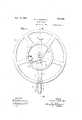
In the accompanying drawings, constituting a part hereof and in which like reference characters designate like parts- Figure 1 is a plan view of a control mechanism embodying the principles of my in* vention,
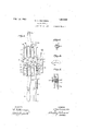
Fig 2 is a diagrammatic view illustrating the manner of connecting the control member to the motor control and regulating device,
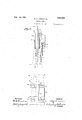
Fig. 3 is a View, partially in section and partially in elevation, of the control mechanism taken along the line IIIIII of Fig. 1,
Fig'. 4 is a fragmentary portion of the control mechanism showing the stop pin by means of which the several sheave wheels are interlocked,
Fig. 5 is a side elevational view of the key which is pivotally mounted in the control head,
Fig. 6 is a longitudinal sectional view of the pivot member showing the manner of mounting the key,
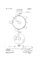
Fig. 7 is a fragmentary view of one of the sheave wheels,
Fig. 8 is a plan view of the base member, and
Fig. 9 is a plan view of the pole changing lever embodied in the control mechanism.
Referring to Fig. 3, the control mechanism comprises a base 1 which is adapted. to be secured tothe headache post of an oil well drilling rig in such manner that the handle portions 2 and 3 of the sheave wheel and pole changing lever are vertically disposed and in an extremely low position. The base member 1 is provided with a center opening 4 adapted to receive a spindle or stud shaft 5 which is secured to the base in any suitable manner as by a dowel pin 6. A pole changer lever 7 is pivotally mounted to the shaft 5 and comprises two projecting portions 8 and 9 respectively, the latter termmatin in the handle portion 3, which is provided with a handle that is pivotally connected thereto and associated tit) with av rod 11 which is movable (to-axially with the lever 7. The rod 1.1 is provided with a sleeve 12 having a spring 13 resting against a flange thereot and the spring 13 further engages one of a pair of lugs 14 attached to the portion 9 ot the lever, through which lugs the rod 11 is adapted to extend into a pair of openings 15 provided in a. vertically projecting segment portion 16 ot the base member 1. A. pair of sheave wheels 17 and 18 having peripheral grooves 19 provided therein are pivotally mounted on the shaft member 5 and a cover plate 20 1s secured to the latter by a cap bolt 21 and dowel pin 21a.
The wheel 17 is provided. with a hand wheel 22 having the handle 2 projeeing theretrom and is further provided with a stop lug 23 adapted to engage a depending portion 2st 01. the wheel 18. The wheel 17 is further provided with an opening which is adapted to receive a spring supported stop pin 26 having a knurled head 27, Fig. 41. The pin 26 is provided with ashoulder 28 to support a spring member 29 that is disposet? around the pin and adapted to rest against the lower face of the-wheel 18. V
The wheels 17 and 18 are provided with plurality of openings 30, 31, 32 and 33 respectively. The upper sheave wheel 18 and the cover plate 20 are provided with openings to give access to a grease cup Slwhich provides lubrication to the several pivot members and to permit releasing of the stop pin 26 when the relative position of the wheel 18 and cover plate 20 is such. that the pin 26 and opening in the plate register. The wheel 17 and pole changing lever 7 are provided with notches 35 and 36, as shown in Figs. 3, 7 and 9 respectively, which are adapted to engage a doulile-acting key member 37 to prevent the pole changing lever and the control operating levers from being moved at the same time. The key is pivotally secured by a pin 38 in a slotted opening 39 ot the shaft member ti. The engaging faces ol the key 37 are bevelled to correspond to the shape of the openings 35 and 36 whereby they readily slip into and out of en- Q'ttfffilntnt.
Referring to Fig. 2, the control mechanisn'i is operatively connected to a pair of controllcrs ll) and. t]. and a pair of pole changers 42 and 4:3. The controllers are provided with sheave wheels l l and 45 and the pole rhangers with pivot yokes 16 and 47. the latter being connected by parallel levers 18 which are pivotally secured thereto.
The controller sheave 41 is connected to the control mechanism by a guy wire 49, one end of which is secured in the openin 30 and the other end in the opening 31 of the sheave wheel 17 7 Fig. 3. The controller wheel 45 is similarly connected by a guy Wire 50, which is secured in the openings 32 and 33 respectively of the sheave wheel. 18. The pole changer is connected by a wire 51 to openings 52 and 53 in the pole changing lever 7.
Referring to Figs. 2 and 3. the operation of this device is briefly as follows: By interlocking the sheave Wheels 17 and 18 by the pin 26, they are jointly operative by manipulating the handle 2 or hand wheel 22. The sheave member 17 may be operated independently of the sheave wheel 18 by releasing the stop pin 26, this being accon'iplished by simply lifting the same out of the opening 25 provided in the sheave wheel 17 only when the pin 26 registers with the opening in the plate 20. It is necessary to provide independent operation ot the wheels 17 and 18 as it is found necessary to regulate the controllers 10 and. 41 individually for the drive motors. On the other hand, the pole changers are operated sin'mltaneously by means of the lever 7.
The pole changing lever 7 and the control operating sheaves 17 and 18 are prevented from operating at the same time by the dou ble key 37 pivoted in the stud shaft 5. The sheave wheel 17 must have its keyway or notch 35 registered with the key 37 before the pole changing lever is operative, for in this position only which is the neutral. or zero position of the control sheaves 17 will the key 37 slip out of the notches 36 ot' the lever 7 into the notch 35 01 the wheel. 17 lea ving the lever 7 tree to be moved.
Vith the pole changing lever thus movable the control sheave 17 will remain in its neutral position and be immovable until the lever 7 reaches one of the Working positions at which time one of the notches 06 will register with the key 37 and the control operating sheave 17 again becomes movable. (fonsequently, the lever 7 cannot be moved until the sheave wheel 17 is again brought to its neutral position.
lVhen the pole changing lever 7 in one 01 its operating positions, the control operatlug sheave 17 can be moved in either direction and. the sheave wheel 18 will more with the wheel 17 by virtue of its engagement therewith. through the interlocking pin. 2%). The pin 26 will register with the openin in the plate 20 when the control sheaves are in their working positions. The pin may then be disengaged to permit independent opera-- tion (it the wheels 17 and 11% t'or regulating the speed of the motors.
it one of the wheels 17 or It) is reversed. the stop lug 23 will engage the dog 2 lof the wheel 18 and. carry it back to the neutral p sition. The spring 29 on the lock pin 2%; will cause the pin to bear against the web of the wheel 17 until it registers with the opening. 25 when it will of its own accord drop in and interlock the wheels 17 and 18. This arrangement effectually prevents the operator from leaving one controller in an operating ill! position and the other one in neutral or reverse position.
It is evident from the foregoing description of my invention that a headache post control device embodying the principles herein set forth provides simple and efficient means for regulating a pair of drilling mo tors to provide desirable speed torque characteristics for drilling operations. The nature of my device is such as to readily facilitate its application to standard drill rigging and it provides a concentrated control means for the operator in proximity to the drilling tools irrespective of the distance and location of the control members.
Although I have described a specific embodiment of my invention, it will be obvious to those skilled in the art that various modifications may be made in the details of construction, the" mode of operation and in the manner of application without departing from the principles herein set forth.
I claim as my invention:
1. A control mechanism comprising a base, a stud shaft mounted therein, a pair of sheave wheels rotatably mounted on said shaft, a lever pivotally mounted thereon, a pivotal key in said shaft adapted to engage one of said wheels and said lever, a pin for interconnecting said wheels and a cover plate having an opening therein secured to said shaft.
2. A control mechanism comprising a base, a stud shaft mounted therein, a pair of sheave wheels rotatably mounted on said shaft, a lever pivotally mounted thereon, a pivotal key in said shaft adapted to engage one of said wheels and said lever. a pin for interconnecting said wheels and a cover plate having an opening therein secured to said shaft, the opening in said cover plate being located to register with said pin when said wheels are in their neutral position.
A control mechanism comprising a base, a stud shaft mounted therein, a pair of sheave wheels rotatably mounted on said shaft, a lever pivotally mounted thereon, a pivotal key in said shaft adapted to engage one of said wheels and a cover plate having an opening therein secured to said shaft, said wheels and lever being associated with said key in such a manner that the wheel and lever are respectively operative when the one or the other of them are in their neutral position.
4-. A control mechanism comprising a base, a shaft mounted therein, a pair of sheave wheels rotatably mounted on said shaft, a lever pivotally mounted thereon,
means for independently operating said wheels, means for lnterconnectmg said wheels, to operate them jointly and means for preventing the joint operation of said lever and Wheels.
5. A control mechanism comprising a base, a shaft mounted therein, a pair of sheave wheels rotatably mounted on said shaft, a lever pivotally mounted thereon, means for interlocking said lever with one of said wheels, and means for interconnecting said wheels, said wheel interconnecting means being independent of said lever interlocking means.
6. Acontrol mechanism comprisingabase, a shaft mounted therein, a pair of sheave wheel rotatably mounted on said shaft, a lever pivotally mounted thereon, means for interlocking said lever with one of said wheels, and means for interconnecting said wheels, said wheel interconnecting means being independent of said lever interlocking means, and either of said means being eifective when the wheels and levers with which itis associated are in their neutral position.
7. A control mechanism comprising apair of control members and a pole-changing member, manually-operated means for connecting and disconnecting the control members, and means for interlocking one of the control members and the pole-changing member to make the control member operative or inoperative in accordance with the position of said pole-changing member.
8. A control mechanism. comprising a pair of control members and a pole-changing member, manually-operated means for connecting and disconnecting the control members, means for preventing the disconnection of the control members in certain positions, and means for interlocking one of the control members and the pole-changing member to make said control member operative or inoperative in accordance with the position of said pole-changing member.
9. A control mechanism comprising a pair of control members and a pole-changing member, manually-operated means for releasably connecting the control members, and means for interlocking one of the control members and the pole-changing member to make the control member operative or inoperative in accordance with the position of said pole-changing member.
In testimony whereof, I have hereunto subscribed my name this thirteenth day of October, 1924.
WILLIAM H. GRANSDEN.
Priority Applications (1)
| Application Number | Priority Date | Filing Date | Title |
|---|---|---|---|
| US744897A US1617841A (en) | 1924-10-21 | 1924-10-21 | Control device |
Applications Claiming Priority (1)
| Application Number | Priority Date | Filing Date | Title |
|---|---|---|---|
| US744897A US1617841A (en) | 1924-10-21 | 1924-10-21 | Control device |
Publications (1)
| Publication Number | Publication Date |
|---|---|
| US1617841A true US1617841A (en) | 1927-02-15 |
Family
ID=24994379
Family Applications (1)
| Application Number | Title | Priority Date | Filing Date |
|---|---|---|---|
| US744897A Expired - Lifetime US1617841A (en) | 1924-10-21 | 1924-10-21 | Control device |
Country Status (1)
| Country | Link |
|---|---|
| US (1) | US1617841A (en) |
-
1924
- 1924-10-21 US US744897A patent/US1617841A/en not_active Expired - Lifetime
Similar Documents
| Publication | Publication Date | Title |
|---|---|---|
| US1617841A (en) | Control device | |
| US1256072A (en) | Top reaming-machine. | |
| US1375092A (en) | Earth-boring machine | |
| US2440427A (en) | Crown block assembly | |
| US1755079A (en) | Electric-motor control for reversing operations | |
| US2698030A (en) | Valve mechanism | |
| US2020945A (en) | Motor control system | |
| US2298188A (en) | Motor control system | |
| US2167224A (en) | Power steering mechanism | |
| US1838956A (en) | Earth drilling | |
| US2325413A (en) | Master switch and control system combination | |
| US1089615A (en) | Lever. | |
| US1808277A (en) | Mine locomotive | |
| US1299924A (en) | Motor-control system. | |
| US1832634A (en) | Universal electric earth-boring device | |
| US1899703A (en) | Electric motor drive for well drilling equipment | |
| US1794980A (en) | Motor-control system | |
| US1652311A (en) | Headache-post control for electric oil-well equipment | |
| US2512000A (en) | Control for alternating current motors | |
| US2026600A (en) | Well drilling system | |
| US1794446A (en) | Distant control for automotive machines and material-handling machines | |
| US1801865A (en) | Transmission for earth-boring machines | |
| US1850116A (en) | Hoisting mechanism | |
| US910798A (en) | Electric hoist. | |
| US1383704A (en) | Winding or hoisting engine |