US1617618A - Electric condenser - Google Patents
Electric condenser Download PDFInfo
- Publication number
- US1617618A US1617618A US720240A US72024024A US1617618A US 1617618 A US1617618 A US 1617618A US 720240 A US720240 A US 720240A US 72024024 A US72024024 A US 72024024A US 1617618 A US1617618 A US 1617618A
- Authority
- US
- United States
- Prior art keywords
- plates
- condenser
- plate
- rack
- lugs
- Prior art date
- Legal status (The legal status is an assumption and is not a legal conclusion. Google has not performed a legal analysis and makes no representation as to the accuracy of the status listed.)
- Expired - Lifetime
Links
- 239000004020 conductor Substances 0.000 description 1
- 238000009413 insulation Methods 0.000 description 1
- 238000004519 manufacturing process Methods 0.000 description 1
Images
Classifications
-
- H—ELECTRICITY
- H01—ELECTRIC ELEMENTS
- H01G—CAPACITORS; CAPACITORS, RECTIFIERS, DETECTORS, SWITCHING DEVICES, LIGHT-SENSITIVE OR TEMPERATURE-SENSITIVE DEVICES OF THE ELECTROLYTIC TYPE
- H01G5/00—Capacitors in which the capacitance is varied by mechanical means, e.g. by turning a shaft; Processes of their manufacture
- H01G5/04—Capacitors in which the capacitance is varied by mechanical means, e.g. by turning a shaft; Processes of their manufacture using variation of effective area of electrode
- H01G5/06—Capacitors in which the capacitance is varied by mechanical means, e.g. by turning a shaft; Processes of their manufacture using variation of effective area of electrode due to rotation of flat or substantially flat electrodes
Definitions
- sei-iai No. 720,240 Application mea rune 1e, 1924. sei-iai No. 720,240.
- My inyentipn relates to electric condensers and resides 1n the provlsion of improved f means for adjusting vthe capacity thereof.
- At least one of the condenser relation with the slidably supported plate is provided.
- one of the condenser sides f is provided with at least two plates that are movable with respect to the other condenser side and withrespect to each other.
- Gearing is placed ⁇ in actuating relation with both of these relatively movable plates, there beinglost-motion connection between said gearing and one of theplates whereby this plate is not moved during a portion of the movement of the other movable plate, this arrangement enabling the finer adjustment 'of the condenser capacity after the coarser adjustment is secured vby the simultaneous movement of both movable plates.
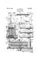
- FIG. 1 is a plan view of a condenser constructed in accordance with the preferred yembodiment of the invention
- Fig. 21's asectional view on line 2-2 of Fig. 1
- Fig'. 3 is a sectional view on line 32-3 of Fig. 1
- Fig. 4 is a view, somewhat diagrammatic, showing three adjustable condenser plates pertaining to one condenser side, the upper condenser plate and contiguous parts being viewed on line 4-4 of Fig. 3, the plate in the intermediate portion of this view and contiguous parts being viewed on line 5-5 of Fig. 3 and the lowermost condenser plate of this view being viewed on line 6 6 of Fig. 3.
- a frame is employed for supporting the condenser sides, this frame beingpreferabh1 rectangular and having its opposite sides 1 and 2 formed with grooves 3 in which the plates 4 of the stator side of the condenser are fixed and grooves 5 alternated with the grooves 3l in which the single plates 6 and 7 and the group of plates 8 of the adjustable condenser side are slidable, the frame thus constituting a guide.
- the frame sides land 2 are of insulation, the remaining sides 9 and- 10 of the frame being preferably metallic.
- the frame side 10 electrically connects the plates 4 of the stator condenser side. Supporting rods 11pass through the frame sides 9 and 10 and are employed to mount the condenser Vupon some suitable support, as the panel 11.
- the grooves 3 for convenience in manufacture, are coextensive with the frame sides 1 and 2, although they need be co-eXtensive only with the pla-tes 4 of the fixed condenser side.
- VThe other grooves are made co-eXtensive with the frame sides 1 and 2 and are suliiciently long to permit the adjustable condenser side to be placed fully in the zone of the fixed or stator side of the condenser and to be moved out of this zone to the extent desired in adjust-ing the condenser capacity.
- yGearing is desirably employed for movingV the plates of the adjustable condenser side.
- This gearing includes pinions that are individual to each plate of the adjustable condenser side.
- These pinions are de- F sirably formed by providing their teeth in the central metallic pinion element 12, the portions of this pinion element which are in the planes of the plates of the adjustable condenser side constituting the pinions that are relatively individual to these plates. rlhe plates of the adjustable condenser side are electrically connected by thevpinion element 12.
- the adjustable condenser side may bel connected with the circuit conductor 12 by means of the binding screw 122 passing through a plate 123 which is interposed between the flange 124 upon the pinion element 12 and the frame side 2.
- a coiled spring 125 surrounds the inner reduced extension of the pinion element 12 and is interposed between a nut 126 on this extension and the stationary plate 127, said spring pressing the flange 124 into irm electrical contact with the plate -'123.
- the pinion element 12 has an outer reduced extension, passing through the panel 11 and equipped with a knob 128 upon its outer end whereby the pinion element may be turned.
- a rack 13 is directly formed upon the condenser plate 6 that is in mesh with the teeth upon the gear element 12.
- the plate 7 isL provided with a rack 14 which is formed upon a metallic bar 15 that is interposed between the lugs 16 upon this plate, the rack bar 15 being shorter than the space between the lugs so that the rack bar may have lost motion before engaging the lug 16 from which it happens to be separated.
- Each of the plates 8 is provided with a rack 17 which is formed upon a metallic rack bar 18 that is interposed between the lugs 19 upon the corresponding plate 8, the rack bar 18 being shorter than the space between the lugs 19 so that each rack bar 18 may have lost motion before engaging the lug 19, from which it is separated.
- the lugs 19 upon the plates 8 are spaced apart equal distances, the space between each pair of lugs 19 being greater than the space between the lugs 16 upon plate 7.
- the rack bars 18, also, are of equal length. When the condenser is adjusted to furnish no capacity the rack bars are in engagement with the lugs to the left of the same and the pinions engaging all of the racks are at the right hand ends of these racks. lVhen the condenser is adjusted to furnish capacity, the pinion element 12 is turned clockwise.
- the plate 6 is the iirst to be moved, the movement of the plate 7 follows, and simultaneous movement o' the plates 8 follows the movement of the plate 7.
- the plate 7 begins to move when the plate 6 reaches the line 2O and all of the plates 8 begin to move when the plates 6 and 7 reach the line 21. It will be observed that the plates havin the racks, the racks and the pinions are a reast of each other, the pinion having a substantially ixed axis of rotation.
- this adjustment may be refined by the movement of plate 6 unaccompanied by the movements of the plates 7 and 8 providing this adjusting movement of the plate 6 is effected while the rack 111 is being moved, in its lost motion range, that is, without moving the plate 7 Similarly,- both plates 6 and 7 may be moved without movingl the plates 8 providing the movements ofthe plates 6 and 7 are e'lected while the rack bars 18 are not in actuating engage- ⁇ ment with the plates 8.
- An electric condenser whose Sides are -formed of plates, one side having two plates that are movable with respect to the other side and with respect to each other, and each provided with a toothed rack, one rack being in lost motion connection with the plate that is provided with it, said condenser also including relatively ixed coaxial pinions meshing with said racks.
- An electric condenser comprising a plurality of spaced fixed plates, a plurality of spaced movable plates shiftable into and out of overlying relation with respect to said iixed plates, a rack individual to each movable plate, and a pinion operatively engaged with all of the racks for shifting said movable plates.
Landscapes
- Engineering & Computer Science (AREA)
- Power Engineering (AREA)
- Microelectronics & Electronic Packaging (AREA)
- Transmission Devices (AREA)
Description
- Feb. l5, 1927.
, 1,617,618 H. A. DOUGLAS Emscmuc commnsn Filed June 16, 1924 l l l Y Patented Peb. 15, 1927.
YUNirED STATES HARRY A. DOUGLAS, OF BRONSON, MICHIGAN.
ELECTRIC CONDEN SER.
Application mea rune 1e, 1924. sei-iai No. 720,240.
My inyentipn relates to electric condensers and resides 1n the provlsion of improved f means for adjusting vthe capacity thereof.
In accordance with one characteristic of my invention, at least one of the condenser relation with the slidably supported plate. A
AIn accordance with another characteristic of the invention, one of the condenser sides f is provided with at least two plates that are movable with respect to the other condenser side and withrespect to each other. Gearing is placed `in actuating relation with both of these relatively movable plates, there beinglost-motion connection between said gearing and one of theplates whereby this plate is not moved during a portion of the movement of the other movable plate, this arrangement enabling the finer adjustment 'of the condenser capacity after the coarser adjustment is secured vby the simultaneous movement of both movable plates.
A The invention will be more fully explained in connection with the accompanying drawing in which Fig. 1 is a plan view of a condenser constructed in accordance with the preferred yembodiment of the invention; Fig. 21's asectional view on line 2-2 of Fig. 1; Fig'. 3 is a sectional view on line 32-3 of Fig. 1 and Fig. 4 is a view, somewhat diagrammatic, showing three adjustable condenser plates pertaining to one condenser side, the upper condenser plate and contiguous parts being viewed on line 4-4 of Fig. 3, the plate in the intermediate portion of this view and contiguous parts being viewed on line 5-5 of Fig. 3 and the lowermost condenser plate of this view being viewed on line 6 6 of Fig. 3.
A frame is employed for supporting the condenser sides, this frame beingpreferabh1 rectangular and having its opposite sides 1 and 2 formed with grooves 3 in which the plates 4 of the stator side of the condenser are fixed and grooves 5 alternated with the grooves 3l in which the single plates 6 and 7 and the group of plates 8 of the adjustable condenser side are slidable, the frame thus constituting a guide. The frame sides land 2 are of insulation, the remaining sides 9 and- 10 of the frame being preferably metallic. y The frame side 10 electrically connects the plates 4 of the stator condenser side. Supporting rods 11pass through the frame sides 9 and 10 and are employed to mount the condenser Vupon some suitable support, as the panel 11. The grooves 3, for convenience in manufacture, are coextensive with the frame sides 1 and 2, although they need be co-eXtensive only with the pla-tes 4 of the fixed condenser side. VThe other grooves are made co-eXtensive with the frame sides 1 and 2 and are suliiciently long to permit the adjustable condenser side to be placed fully in the zone of the fixed or stator side of the condenser and to be moved out of this zone to the extent desired in adjust-ing the condenser capacity.
yGearing is desirably employed for movingV the plates of the adjustable condenser side. This gearing includes pinions that are individual to each plate of the adjustable condenser side. These pinions are de- F sirably formed by providing their teeth in the central metallic pinion element 12, the portions of this pinion element which are in the planes of the plates of the adjustable condenser side constituting the pinions that are relatively individual to these plates. rlhe plates of the adjustable condenser side are electrically connected by thevpinion element 12. The adjustable condenser side may bel connected with the circuit conductor 12 by means of the binding screw 122 passing through a plate 123 which is interposed between the flange 124 upon the pinion element 12 and the frame side 2. A coiled spring 125 surrounds the inner reduced extension of the pinion element 12 and is interposed between a nut 126 on this extension and the stationary plate 127, said spring pressing the flange 124 into irm electrical contact with the plate -'123. The pinion element 12 has an outer reduced extension, passing through the panel 11 and equipped with a knob 128 upon its outer end whereby the pinion element may be turned.-
A rack 13 is directly formed upon the condenser plate 6 that is in mesh with the teeth upon the gear element 12. The plate 7 isL provided with a rack 14 which is formed upon a metallic bar 15 that is interposed between the lugs 16 upon this plate, the rack bar 15 being shorter than the space between the lugs so that the rack bar may have lost motion before engaging the lug 16 from which it happens to be separated. Each of the plates 8 is provided with a rack 17 which is formed upon a metallic rack bar 18 that is interposed between the lugs 19 upon the corresponding plate 8, the rack bar 18 being shorter than the space between the lugs 19 so that each rack bar 18 may have lost motion before engaging the lug 19, from which it is separated. The lugs 19 upon the plates 8 are spaced apart equal distances, the space between each pair of lugs 19 being greater than the space between the lugs 16 upon plate 7. The rack bars 18, also, are of equal length. When the condenser is adjusted to furnish no capacity the rack bars are in engagement with the lugs to the left of the same and the pinions engaging all of the racks are at the right hand ends of these racks. lVhen the condenser is adjusted to furnish capacity, the pinion element 12 is turned clockwise. The plate 6 is the iirst to be moved, the movement of the plate 7 follows, and simultaneous movement o' the plates 8 follows the movement of the plate 7. The plate 7 begins to move when the plate 6 reaches the line 2O and all of the plates 8 begin to move when the plates 6 and 7 reach the line 21. It will be observed that the plates havin the racks, the racks and the pinions are a reast of each other, the pinion having a substantially ixed axis of rotation.
After the capacity ofV the condenser has been coarsely adjusted, this adjustment may be refined by the movement of plate 6 unaccompanied by the movements of the plates 7 and 8 providing this adjusting movement of the plate 6 is effected while the rack 111 is being moved, in its lost motion range, that is, without moving the plate 7 Similarly,- both plates 6 and 7 may be moved without movingl the plates 8 providing the movements ofthe plates 6 and 7 are e'lected while the rack bars 18 are not in actuating engage-` ment with the plates 8.
Changes may be made without departing from my invention.
Having thus described my invention, I claim:
l. An electric condenser whose sides are in lost motion connection with the plate that is provided with it, said condenser also including relatively fixed pinions meshing with said racks.
3. An electric condenser whose Sides are -formed of plates, one side having two plates that are movable with respect to the other side and with respect to each other, and each provided with a toothed rack, one rack being in lost motion connection with the plate that is provided with it, said condenser also including relatively ixed coaxial pinions meshing with said racks.
4. In an electric condenser, a fixed plate, two plates having rectilinear movement into and out oit overlying relation to the xed plate, a single operator for the plates having rectilinear movement, and a lost motion. connection between th-e operator and one of said rectilinearly movable plates.
5. An electric condenser comprising a plurality of spaced fixed plates, a plurality of spaced movable plates shiftable into and out of overlying relation with respect to said iixed plates, a rack individual to each movable plate, and a pinion operatively engaged with all of the racks for shifting said movable plates.
In witness whereof, I hereunto subscribe my name.
HARRY A. DOUGLAS.
Priority Applications (1)
| Application Number | Priority Date | Filing Date | Title |
|---|---|---|---|
| US720240A US1617618A (en) | 1924-06-16 | 1924-06-16 | Electric condenser |
Applications Claiming Priority (1)
| Application Number | Priority Date | Filing Date | Title |
|---|---|---|---|
| US720240A US1617618A (en) | 1924-06-16 | 1924-06-16 | Electric condenser |
Publications (1)
| Publication Number | Publication Date |
|---|---|
| US1617618A true US1617618A (en) | 1927-02-15 |
Family
ID=24893223
Family Applications (1)
| Application Number | Title | Priority Date | Filing Date |
|---|---|---|---|
| US720240A Expired - Lifetime US1617618A (en) | 1924-06-16 | 1924-06-16 | Electric condenser |
Country Status (1)
| Country | Link |
|---|---|
| US (1) | US1617618A (en) |
Cited By (1)
| Publication number | Priority date | Publication date | Assignee | Title |
|---|---|---|---|---|
| US3156884A (en) * | 1962-04-30 | 1964-11-10 | Aladdin Ind Inc | Ultra high frequency tuner having rectilinearly sliding plates providing variable inductance and capacitance |
-
1924
- 1924-06-16 US US720240A patent/US1617618A/en not_active Expired - Lifetime
Cited By (1)
| Publication number | Priority date | Publication date | Assignee | Title |
|---|---|---|---|---|
| US3156884A (en) * | 1962-04-30 | 1964-11-10 | Aladdin Ind Inc | Ultra high frequency tuner having rectilinearly sliding plates providing variable inductance and capacitance |
Similar Documents
| Publication | Publication Date | Title |
|---|---|---|
| US1707959A (en) | Condenser | |
| US1617618A (en) | Electric condenser | |
| DE587964C (en) | Electrical capacitor of high capacitance, the band-shaped coverings of which are separated by insulating layers and protruding over the winding body at both ends are wound on a flangeless tube that is open at both ends | |
| US1610122A (en) | Adjustable condenser | |
| US1632130A (en) | Condenser | |
| US1508647A (en) | Variable condenser | |
| US1772839A (en) | Tuning unit | |
| US1568274A (en) | Condenser | |
| DE754566C (en) | Electric pressure switch | |
| US1592775A (en) | Variable condenser | |
| US1629867A (en) | Electrical condenser | |
| US1745949A (en) | Variable condenser | |
| US1583634A (en) | Variable condenser | |
| US2078522A (en) | Radio condenser | |
| US2031910A (en) | Condenser | |
| US1571370A (en) | Variable condenser | |
| US1634930A (en) | Variable condenser | |
| US1712165A (en) | Multiple condenser | |
| US1606660A (en) | Electrical condenser | |
| US1738195A (en) | Electrical condenser | |
| US1738369A (en) | Control for variable radio tuning units | |
| US1713867A (en) | Electrical | |
| US890858A (en) | Electric heating device. | |
| US832632A (en) | Multiple contact for electrical condensers. | |
| US1705242A (en) | Variable condenser |