US1608994A - Winch - Google Patents
Winch Download PDFInfo
- Publication number
- US1608994A US1608994A US471865A US47186521A US1608994A US 1608994 A US1608994 A US 1608994A US 471865 A US471865 A US 471865A US 47186521 A US47186521 A US 47186521A US 1608994 A US1608994 A US 1608994A
- Authority
- US
- United States
- Prior art keywords
- motor
- drums
- pillars
- drum
- casing
- Prior art date
- Legal status (The legal status is an assumption and is not a legal conclusion. Google has not performed a legal analysis and makes no representation as to the accuracy of the status listed.)
- Expired - Lifetime
Links
- 239000011435 rock Substances 0.000 description 13
- 239000012530 fluid Substances 0.000 description 11
- 230000002441 reversible effect Effects 0.000 description 5
- 230000033001 locomotion Effects 0.000 description 4
- 230000007935 neutral effect Effects 0.000 description 4
- 230000005540 biological transmission Effects 0.000 description 1
- 230000000295 complement effect Effects 0.000 description 1
- 230000003247 decreasing effect Effects 0.000 description 1
- 230000007717 exclusion Effects 0.000 description 1
- CNQCVBJFEGMYDW-UHFFFAOYSA-N lawrencium atom Chemical compound [Lr] CNQCVBJFEGMYDW-UHFFFAOYSA-N 0.000 description 1
Images


Classifications
-
- B—PERFORMING OPERATIONS; TRANSPORTING
- B66—HOISTING; LIFTING; HAULING
- B66D—CAPSTANS; WINCHES; TACKLES, e.g. PULLEY BLOCKS; HOISTS
- B66D1/00—Rope, cable, or chain winding mechanisms; Capstans
- B66D1/02—Driving gear
- B66D1/08—Driving gear incorporating fluid motors
-
- B—PERFORMING OPERATIONS; TRANSPORTING
- B66—HOISTING; LIFTING; HAULING
- B66D—CAPSTANS; WINCHES; TACKLES, e.g. PULLEY BLOCKS; HOISTS
- B66D2700/00—Capstans, winches or hoists
- B66D2700/01—Winches, capstans or pivots
- B66D2700/0125—Motor operated winches
- B66D2700/0133—Fluid actuated
Definitions
- Patented av. 30, 1926 I mart ALBERT aliases, or 'irrntaosn em nating. iaassaorrnss rrs, Assreroa ro GEORGE H. GILMAN, or Bos'ron, MASSACHUSETTS.
- Fig. 1 shows an elevation of a winch constructed according to my invention
- Fig. 2 is a plan view according to Fig. 1;
- Fig. 3 is a section on the line 33 of Fig. lwithparts omitted;
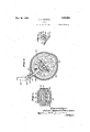
- Fig. 1 is a section on. the line 44 of Fig. 3;
- Fig. 5 is a section on the line 5-5 of Fig. 3;
- Figs. 6 and 7 respectively are sections on the lines 6'6' and 7'7 of Fig. i; V
- Fig. 8 is a section on the line 8-8 of Fig. 4.
- Fig. 9 is a fragmentary section on the line 9-9 of Fig. 2.
- I have provided a pair of drums 1 and a motor 3 located between the drums for operating them, the machine being supported on a mine column 5, or similar contrivance, by spaced feet 7 carried by the motor and cooperating with clamps 9 secured to the feet by the bolts 11.
- the motor shown is of the fluid pressure rotary engine type but it will be understood other types of motor may be used.
- the motor shown comprises a centrally located rotor, indicated in its entirety at 13, cooperating with the rotary gear members. the latter indicated in their entirety at and serving as pressure abutments for the pressure surfaces of the central rotor.
- the rotor comprises a wheel having a rim 17 on the periphery of which are formed the spaced piston vanes in the shape of gear teeth 19, the sides of the rim being cut away to provide shoulders carrying the annuli 21 on which are formed the continuous series of gear teeth 23 of smaller size than the gear teeth 19 but preferably of the same pitch diameter.
- the ab-utm'ents similarly are formed with a centrally located member 25 1921. $eria1 No. 471,865.
- each pinion 29 is in the form of an annulus similar to each of the annuli 21, and is supported on the member 25 which is cut away in the same manner as the rim 17 to form a shouldered portion for receiving the pinion as shown by Fig. 8. It will be noted the continuous series of smaller gear teeth cause the larger teeth 19 of the-rotor to mesh with the recesses 27 of the abutments, and that by providing the teeth 19 of greater depth than the teeth 23 I increase the pressure surface on which the motive fluid may act.
- a casing Surrounding the rotor and abutments is a casingcomprising a central ring 30 and side rings 31, these members being so shaped as to conform with the faces of the teeth 19 and 23 of the rotor and the faces of the corresponding parts of the abutments', as is best shown by Fig. 4:.
- the sides of the motor casing are formed by the members 33, which fit in a fluid tightm'anner the opposite sides of the members 17 and 21 of the rotor and the corresponding members of the abutments.
- Adjacent the peripheries of the motor casing the members 30, 31 and 33 are formed with the shoulder portions 35 which, when the casing is assembled, fit each other to hold the parts in alignment. For holding them in assembled relation I provide the bolts 37.
- integrally formed with the member 25 of the abutments is a shaft 39 journalled in the raised portions 41 formed integrally with the motor casing members 33.
- the members 21 may be secured to the member 17 of the rotor, and similarly the pinions may be secured to the central member 25 of the abutments, in any suitable manner such as by riveting or shrinking them in place.
- I have indicated these parts as keyed together by means of the screw-key 12, one of which is shown in Fig. 3.
- This valve is provided with a conduit 19 opening through the end of the valve opposite the handle so as to be in constant comniunication with the motive fluid supply conduit 51.
- Placing the conduit 49 in communication with the exterior of the valve are the spaced passages 53 and 55, while in the same plane with these conduits respectively are formed on the exterior of the Valve the arcuate grooves 57 and 59, each of the latter respectively being placed in permanent communication with the atmosphere by passages 61 and 63 formed through the valve casing.
- passages 65 and 67 In the wall of the casing member 30 I provide passages 65 and 67, each respectively placed in communication with the valve seat by communicating passages 69 and 71, the latter respectively opening on the valve seat in the plane of the passages 53 and 55 of the valve.
- the passage 67 opens into the interior of the motor casing adjacent two diametrically opposite points of intersection of the portions of the casing fitting the rotor and its abutments, while the passage 65 opens into the interior of the casing adjacent the points of intersection opposite these as illustrated by Fig. 4.
- the motive fluid in this way admitted traveling in the same directions as the rotor and abutments and escaping to the atmosphere through the passage 65 in communication with the opposite points of intersection of the rotor and abutments. If the valve is moved counterclockwise from its neutral position as viewed in 6 and 7 the passage 65 will be connected to the source of motive fluid supply while the passage 67 will be connected to the atmosphere and this will drive the rotor counterclockwise. It will be noted by the means described I have provided a reversible motor.
- each drum herein is provided with the end flanges 75 and 77, the latter being provided with the annular extension 79, the exterior surface of which cooperates with the brakeband 81, and the inner face of which rests against the annular housing 83 carried by the motor casing.
- I herein provide a plate 85 secured to the ends of the shafts in any suitable manner as for example by screws 87.
- the rotor of the motor herein carries oppositely extending shafts 89 which are journaled in the bores 91 formed axially of the pillars 73 and opening into the interior of the motor casing.
- the intermediate portion of each shaft 89 has formed thereon a series of gear teeth 93, which mesh with the gear wheel 95 keyed to the hub of the pinion 97 rotatively mounted on a stud 99 carried by the side member 33 of the motor casing.
- each pinion 93 meshes with an internal gear 101 carried by a clutch member 103.
- the clutch member 103 just referred to is provided in the illustrative embodiment of my invention with the conical face 105 adapt-- ed to be forced into engagement with a complementary interior face 107 formed on the portion 79 of the drum.
- the shafts 89 of the motor drive the drums by way of the reduction gearings afforded by the gear wheels 95, the pinions 97 and the internal gears 101, and as the motor may be reversed, the drums may be driven in either of two directions.
- Each clutch element 103 is herein provided with an annular sleeve 109 which slides on the exterior surface of one of the shafts 73 and is normally biased to disengaging position by means of a spring 111, which abuts at one end the drum and at the other end the outer face of the sleeve.
- each lever For operating the clutches I have illustrated levers fulc-rumed at 113 to lugs carried on the sides of the motor casing, each lever having the bifurcated portions 115 carrying at their outer ends the antifriction rollers 117 which bear against the inner face of the clutches.
- Each lever as illustrated has an operating arm 119 connected by means of a loosely fitting pin 121 to a block 123.
- rock shafts 125 For operating the clutch and brake I herein provide the separate rock shafts 125 supa ported in lugs 127 and 129 carried by the motor casing. Each rock shaft is held in position by a collar 131 carried by the rock shaft and abutting one side of a lug 125, the other side of the lug being abutted by the shoulder afforded by the increased diameter portion 133 of the rock shaft. Any suitable mechanism may be provided for moving the block 123 when the brake is dis engaged and as herein shown I have provided a cam connection by forming on each portion 133 of the rock shafts a high pitch screw-thread 125 and the block with cooperating threads in engagement therewith.
- the reek shaft is adapted to be turned by means of the lever 13? carried by the outer end of the rock shaft; When the lever turned, the nut is moved along the screwtlireaded portion to force the clutch into and out of engagement.
- Thelower portions of the levers 137 are herein provided with the studs ,138 and 141, to which the opposite ends of the brakebands 81 are secured, WVhen the levers are in the position illustrated by Fig; 1, the brake bands will be loose and anticlockwise movement of the levers frem this position will cause the brake-bands frictionally to engage the drums. Clockwise movement will cause the brake-bands further to be leosened and will cause the nut to move, in such direction as to cause engagement of the clutch.
- each shaft With the oppositely coiled torsional springs 1&5 and 147, each spring surroiinding the shaft and having an end looped around the opposite projecting ends of the pin 149 carried by theshaft, the opposite ends lel of the coils being eX- tei ded and bearing against the exterior of the motor casing. It will be noticed by this const'riiction rotation of the rock shaft in either direction frhm the neutral position is opposed by one or theother of the springs associated with the shaft in order that when the lever 1371s released, the rock shaft will return to neutral position.
- a pair of axially aligned drums a motor for operatingsaid dru 'ns and located between them, supporting pillars for said drums ex tending from opposite sides ofv said motor, sa'id pillars' being non-rotatable, and said drums being, rotatably mounted on said pillars.
- a pair of drums a motor for operating said drums and located between them, supporting pillars for said drums extending from opposite sides of said motor, said pillars being lion-rotatable, and said drums being rotatably mounted on said pillars.
- a member adapted to be attached to a suppei't, separ:-ite oppositely extending non-rotatable pillars supported at one end only by said member, drun' s on said pillars, a motor situated between the ends of said pillars, and separate means actuated by said motor for driving said drums.
- a motor casing non-rotatable pillars extending from opposite sides of said casing, a drum on each pillar, and power transmis sion means between said motor and drums.
- a support oppositely extending pillars nonrotatably carried by said support, plurality of drums mounted on said pillars, a reversible motor between said drums, and means for operatively connecting either or both of said drums to'said motor.
- a support oppositely exten'dingpillars nonrotatably carried by said support, a plurality of drums mounted on said pillars, and means including a reversible motor between said pillars for causing said drums to be driven simultaneously or one to the exclusion of the other in either of opposite directions.
- a support a motor carried by said support, a hollow pillar carried by said motor, a drum rotatably mounted on said pillar, said motor having a shaft extending into the end of said pillar adjacent said casing and was ably supported thereby, said shaft carrying gear teeth, and means for connecting said gear teeth to said drum comprising a gear extending through a lateral opening in the wall of said pillar and meshing With said gear teeth.
- a motor having a casing, a hollow pillar carried by said casing, a drum journalled on said pillar, said motor having a shaft extending into the end of said pillar adjacent said casing and rotatably supported thereby, and gearing extending through a lateral opening in said pillar operatively connecting said shaft and drum.
- a rotary gear toothed member oppositely extending shafts carried by said member, drums carried in alignment with said shafts, oppositely extending non-rotatable pillars, said shafts extending into said pillars and being rotatably supported by said pillars internally thereof, said drums surrounding said pillars and being rotatably supported thereby.
- a pair of spaced drums a motor having a rotary element between said drums, oppositely extending shafts carried by said element, nonrotatable pillars surrounded by and ro tatably carrying said drums and rotatably supporting said shafts, and reduction gearing connecting said shafts and drums.
- a reversible fluid pressure motor having a rotor with oppositely extending shafts, a pair of oppositely extending non-rotatable pillars, drums surrounding and rotatably carried by said pillars in alignment with said shafts, said shafts extending into the ends of said pillars and being rotatably supported thereby, and reduction gearing con necting said shafts and drums.
- a motor casing having a shaft the ends of which are journaled in said pillars, drums mounted for rotation on said pillars, gears on said shafts, said pillars having lateral openings adjacent the gears on said shafts, gears supported on said casing and extending into said lateral openings to mesh with said gears on said shafts, and means for operatively connecting said gears supported on said casing to said drums.
- a capstan a pillar, a drum on said pillar, a motor casing supporting said pillar at one end, said motor having a shaft journaled in the end of said pillar adjacent said casing, said shaft having a gear thereon internally of said pillar, said pillar having a lateral opening adjacent said gear, and means for driving said drum comprising a gear journalled exteriorly of said pillar and extending into said lateral opening and meshing with said gear on said shaft.
- a motor casing having means for attachment to a support, said casing having heads each carrying one end of a pillar, and a drum on each pillar.
- a motor casing having means for attachment to a support, said casing having heads each carrying one end of the respective pillars of a pair of pillars, drums on said pillars, said motor having a shaft rotatably supported by said pillars, and means connecting said shaft to said drums.
- a motor in a device of the character described, a motor, its shaft, a. pillar carried at one end by said motor and aligned with the shaft of said motor, a drum on the unsupported end of said pillar, a clutch element, rotatably supported on said pillar between said motor and drum, gearing connecting said motor shaft and element, a clutch element carried by said drum, and means for moving said clutch elements into engagement.
- a motor oppositely extending shafts for said motor, a pair of drums, a pillar for each drum carried by said motor and aligned with the shafts of said motor, a pair of clutch elements, gearing connecting each clutch element respectively to a motor shaft, a clutch element carried by each drum, and means for moving the clutch elements into engagement to cause said drums to be driven.
- a drum a motor for driving said drum, a pillar carried at one end by said motor and supporting said drum, a clutch device comprising a sliding gear surrounding said pillar and driven by said motor for connecting said motor and drum in driving relation, a brake device for said drum, mechanism for operating one of said devices, and cam means responsive to movement of said mechanism for operating the other of said devices.
- a drum In a device of the character described, a drum, a motor for driving said drum, a
- a clutch comprising a sliding gear surrounding said pillar and driven by said motor for connecting said motor and drum in driving relation, a brake for said drum, mechanism for operating said brake and including a rock shaft carried by said motor, a screw carried by said shaft, and means including a nut cooperating with said screw for causing motion of said shaft to operate said clutch.
- a drum a motor for driving said drum, a pillar carried at one end by said motor and supporting said drum, a clutch comprising a sliding gear surrounding said pillar and driven by said motor for connecting said motor and drum in driving relation, a brake for said drum, spring means normally relieving said brake and holding said clutch in disengaged position, and mechanism for varying the braking action and having means for engaging said clutch when the braking action is decreased.
- a reversible motor a plurality of drums supported on separate pillars extending from opposite sides of said motor, a brake for each drum, a clutch for connecting each drum in driving relation to said motor, and independent means at opposite sides of said motor for coordinately operating the brake and clutch for each drum.
- a motor a drum supported on a pillar extending from said motor, a brake for said drum, a clutch comprising a sliding gear on said pillar for connecting said drum to said motor, a rock shaft on said motor for operating said b ake and carrying a screw, a nut carried by said screw, and a lever operatively connecting said nut and sliding gear.
- a motor of the type having a rotary piston and a cooperating rotary abutment driven by the piston, a casing for said piston and abutment, pillars extending from opposite sides of said casing, a shaft for said rotary piston rotatably supported at opposite ends by said pillars, gearing means in said casing for timing said abutments With said piston, and independent gearing means exterior of said casing connecting said shafts to said drums.
- a motor casing pillars carried at one end thereof at opposite sides of said casing, a motor shaft rotatably supported at opposite ends by said pillars, drums on said pillars, gearing connecting said drums to said shafts, said gearing comprising internal gears slidably and rotatably mounted on said pillars, said internal gears having external clutch elements, and said drums having brake flanges provided With internal clutch elements for engaging said external clutch elements.
- a motor casing a pillar extending from said motor casing, a motor shaft rotatably sup ported by said pillar, a drum having a bearing on said pillar, a reduction gearing and a clutch between said bearing for said drum and said motor casing, said reduction gearing and clutch comprising a gear and clutch element rotatably and slidably mounted on said pillar and driven by said motor shaft, a brake for said drum, a rock shaft for operating said brake, cam means actuated by said rock shaft, and a lever cooperating with said cam means for sliding said gear and clutch element.
- a motor said motor having a casing provided vvith mleans for detachably connecting it to a mine column or the like With the axis of said motor spaced from the axis of said column and lying in a plane parallel to the axis of said column, heads for said motor casing, each head carrying a projecting pillar, said pillars being in alignment, drums on said pillars, and separate reduction gearings and clutches connecting each drum to said motor.
Landscapes
- Engineering & Computer Science (AREA)
- Mechanical Engineering (AREA)
- Connection Of Motors, Electrical Generators, Mechanical Devices, And The Like (AREA)
Description
4 Sheets-Sheet 2 WINCH r 8 y 3 w 0x ox .1 A w HQ :m :M/ R -m .mx, h y
Nov. 30 1926.
J. A; PIERSON WINCH Filed May 1921 4 Sheets-Sheet 3 I Nov. 30 192 6 J. A. PIERSON WINCH Filed May 23, 192] 4 Sheets-Sheet 4 Inveni or:
ahhncfliberiBv'e-rsofl a a y M v I 24%, 05152295.
Patented av. 30, 1926 I mart ALBERT aliases, or 'irrntaosn em nating. iaassaorrnss rrs, Assreroa ro GEORGE H. GILMAN, or Bos'ron, MASSACHUSETTS.
wmon.
Application iiled May as,
My invention relates to winches and more particularly but not exclusively to a portable winch for use in mines. My invention will be best understood from the following description when read in the light of the accompanying drawings of a specific embodiment of my invention selected for illustrative purposes, whilev the scope of my invention will be more particularly pointed out in the appended claims. Referring to the drawings Fig. 1 shows an elevation of a winch constructed according to my invention;
Fig. 2 is a plan view according to Fig. 1;
Fig. 3 is a section on the line 33 of Fig. lwithparts omitted;
Fig. 1 is a section on. the line 44 of Fig. 3;
Fig. 5 is a section on the line 5-5 of Fig. 3;
Figs. 6 and 7 respectively are sections on the lines 6'6' and 7'7 of Fig. i; V
Fig. 8 is a section on the line 8-8 of Fig. 4; and
Fig. 9 is a fragmentary section on the line 9-9 of Fig. 2.
Referring to the illustrative embodiment of my invention shown by the drawings, I have provided a pair of drums 1 and a motor 3 located between the drums for operating them, the machine being supported on a mine column 5, or similar contrivance, by spaced feet 7 carried by the motor and cooperating with clamps 9 secured to the feet by the bolts 11. The motor shown is of the fluid pressure rotary engine type but it will be understood other types of motor may be used.
Referring particularly to Figs. 3 and a, it will be noted. the motor shown comprises a centrally located rotor, indicated in its entirety at 13, cooperating with the rotary gear members. the latter indicated in their entirety at and serving as pressure abutments for the pressure surfaces of the central rotor. Herein the rotor comprises a wheel having a rim 17 on the periphery of which are formed the spaced piston vanes in the shape of gear teeth 19, the sides of the rim being cut away to provide shoulders carrying the annuli 21 on which are formed the continuous series of gear teeth 23 of smaller size than the gear teeth 19 but preferably of the same pitch diameter. The ab-utm'ents similarly are formed with a centrally located member 25 1921. $eria1 No. 471,865.
provided with recesses 27 shaped to mesh with the gear teeth 19, and at each side of the member 25 is provideda pinion 29 in mesh with the teeth 23 of the rotor. Each pinion 29 is in the form of an annulus similar to each of the annuli 21, and is supported on the member 25 which is cut away in the same manner as the rim 17 to form a shouldered portion for receiving the pinion as shown by Fig. 8. It will be noted the continuous series of smaller gear teeth cause the larger teeth 19 of the-rotor to mesh with the recesses 27 of the abutments, and that by providing the teeth 19 of greater depth than the teeth 23 I increase the pressure surface on which the motive fluid may act.
Surrounding the rotor and abutments is a casingcomprising a central ring 30 and side rings 31, these members being so shaped as to conform with the faces of the teeth 19 and 23 of the rotor and the faces of the corresponding parts of the abutments', as is best shown by Fig. 4:. The sides of the motor casing are formed by the members 33, which fit in a fluid tightm'anner the opposite sides of the members 17 and 21 of the rotor and the corresponding members of the abutments. Adjacent the peripheries of the motor casing the members 30, 31 and 33 are formed with the shoulder portions 35 which, when the casing is assembled, fit each other to hold the parts in alignment. For holding them in assembled relation I provide the bolts 37.
As illustrated, integrally formed with the member 25 of the abutments is a shaft 39 journalled in the raised portions 41 formed integrally with the motor casing members 33. The members 21 may be secured to the member 17 of the rotor, and similarly the pinions may be secured to the central member 25 of the abutments, in any suitable manner such as by riveting or shrinking them in place. In the drawings, I have indicated these parts as keyed together by means of the screw-key 12, one of which is shown in Fig. 3.
For controlling the motor I herein form at theside of the member 30 of the motor casing a projection 43 bored to form a valve seat for the valve 45-,the latter being provided with an operating handle 47. This valve is provided with a conduit 19 opening through the end of the valve opposite the handle so as to be in constant comniunication with the motive fluid supply conduit 51. Placing the conduit 49 in communication with the exterior of the valve are the spaced passages 53 and 55, while in the same plane with these conduits respectively are formed on the exterior of the Valve the arcuate grooves 57 and 59, each of the latter respectively being placed in permanent communication with the atmosphere by passages 61 and 63 formed through the valve casing. In the wall of the casing member 30 I provide passages 65 and 67, each respectively placed in communication with the valve seat by communicating passages 69 and 71, the latter respectively opening on the valve seat in the plane of the passages 53 and 55 of the valve. The passage 67 opens into the interior of the motor casing adjacent two diametrically opposite points of intersection of the portions of the casing fitting the rotor and its abutments, while the passage 65 opens into the interior of the casing adjacent the points of intersection opposite these as illustrated by Fig. 4.
When the valve is in the position illustrated by Figs. 1, 6 and 7, communication between both the atmosphere and the source of motive fluid supply with the interior of the casing is interrupted. If the valve is turned clockwise as view in Figs. 6 and 7 the passage 69 will be connected to the atmosphere by way of the groove 57 and passage 61, while the passage 71 will be connected to the source of motive fluid supply by means of the internal conduit 49 of the valve and the passage 55 thereof. This will connect the passage 67 to the source of motive fluid and the passage 65 to the atmosphere and will in consequence admit motive fluid to the upper right hand and lower left hand points of intersection of the rotor and abutments, as viewed in Fig. 1. This will drive the rotor clockwise as viewed in Fig. t and the abutments anticlockwise, the motive fluid in this way admitted traveling in the same directions as the rotor and abutments and escaping to the atmosphere through the passage 65 in communication with the opposite points of intersection of the rotor and abutments. If the valve is moved counterclockwise from its neutral position as viewed in 6 and 7 the passage 65 will be connected to the source of motive fluid supply while the passage 67 will be connected to the atmosphere and this will drive the rotor counterclockwise. It will be noted by the means described I have provided a reversible motor.
As illustrated, extending outwardly from the side members 33 of the motor casing are the oppositely extending pillars 73 on the outer ends of which are journaled the drums. Each drum herein is provided with the end flanges 75 and 77, the latter being provided with the annular extension 79, the exterior surface of which cooperates with the brakeband 81, and the inner face of which rests against the annular housing 83 carried by the motor casing. For holding the drums in place I herein provide a plate 85 secured to the ends of the shafts in any suitable manner as for example by screws 87.
The rotor of the motor herein carries oppositely extending shafts 89 which are journaled in the bores 91 formed axially of the pillars 73 and opening into the interior of the motor casing. As illustrated, the intermediate portion of each shaft 89 has formed thereon a series of gear teeth 93, which mesh with the gear wheel 95 keyed to the hub of the pinion 97 rotatively mounted on a stud 99 carried by the side member 33 of the motor casing. Herein each pinion 93 meshes with an internal gear 101 carried by a clutch member 103.
The clutch member 103 just referred to is provided in the illustrative embodiment of my invention with the conical face 105 adapt-- ed to be forced into engagement with a complementary interior face 107 formed on the portion 79 of the drum. When the clutch elements so formed are in engagement and the motor is in operation, the shafts 89 of the motor drive the drums by way of the reduction gearings afforded by the gear wheels 95, the pinions 97 and the internal gears 101, and as the motor may be reversed, the drums may be driven in either of two directions.
Each clutch element 103 is herein provided with an annular sleeve 109 which slides on the exterior surface of one of the shafts 73 and is normally biased to disengaging position by means of a spring 111, which abuts at one end the drum and at the other end the outer face of the sleeve.
For operating the clutches I have illustrated levers fulc-rumed at 113 to lugs carried on the sides of the motor casing, each lever having the bifurcated portions 115 carrying at their outer ends the antifriction rollers 117 which bear against the inner face of the clutches. Each lever as illustrated has an operating arm 119 connected by means of a loosely fitting pin 121 to a block 123.
For operating the clutch and brake I herein provide the separate rock shafts 125 supa ported in lugs 127 and 129 carried by the motor casing. Each rock shaft is held in position by a collar 131 carried by the rock shaft and abutting one side of a lug 125, the other side of the lug being abutted by the shoulder afforded by the increased diameter portion 133 of the rock shaft. Any suitable mechanism may be provided for moving the block 123 when the brake is dis engaged and as herein shown I have provided a cam connection by forming on each portion 133 of the rock shafts a high pitch screw-thread 125 and the block with cooperating threads in engagement therewith.
(iii
its
The reek shaft is adapted to be turned by means of the lever 13? carried by the outer end of the rock shaft; When the lever turned, the nut is moved along the screwtlireaded portion to force the clutch into and out of engagement.
Thelower portions of the levers 137 are herein provided with the studs ,138 and 141, to which the opposite ends of the brakebands 81 are secured, WVhen the levers are in the position illustrated by Fig; 1, the brake bands will be loose and anticlockwise movement of the levers frem this position will cause the brake-bands frictionally to engage the drums. Clockwise movement will cause the brake-bands further to be leosened and will cause the nut to move, in such direction as to cause engagement of the clutch. For holding rock shafts normally in their neutral position in which the brake and clutch both are disengaged, I herein provide each shaft with the oppositely coiled torsional springs 1&5 and 147, each spring surroiinding the shaft and having an end looped around the opposite projecting ends of the pin 149 carried by theshaft, the opposite ends lel of the coils being eX- tei ded and bearing against the exterior of the motor casing. It will be noticed by this const'riiction rotation of the rock shaft in either direction frhm the neutral position is opposed by one or theother of the springs associated with the shaft in order that when the lever 1371s released, the rock shaft will return to neutral position. v
Although I have described for purposes of illustration one specific embodiment of my invention it is to be understood that I am not limited thereby, but that wide deviations may be made therefrom Without departing from the spirit of my invention.
I claim p I v v e 1. In a device of the character described,
a pair of axially aligned drums, a motor for operatingsaid dru 'ns and located between them, supporting pillars for said drums ex tending from opposite sides ofv said motor, sa'id pillars' being non-rotatable, and said drums being, rotatably mounted on said pillars.
2. In a device of the character described, a pair of drums, a motor for operating said drums and located between them, supporting pillars for said drums extending from opposite sides of said motor, said pillars being lion-rotatable, and said drums being rotatably mounted on said pillars.
In a device ofth'e character described, a member adapted to be attached to a suppei't, separ:-ite oppositely extending non-rotatable pillars supported at one end only by said member, drun' s on said pillars, a motor situated between the ends of said pillars, and separate means actuated by said motor for driving said drums.
4. In a device of the character described, a motor casing, non-rotatable pillars extending from opposite sides of said casing, a drum on each pillar, and power transmis sion means between said motor and drums.
5. In a device of the character described, a support, oppositely extending pillars nonrotatably carried by said support, plurality of drums mounted on said pillars, a reversible motor between said drums, and means for operatively connecting either or both of said drums to'said motor.
6. In a device of the character described, a support, oppositely exten'dingpillars nonrotatably carried by said support, a plurality of drums mounted on said pillars, and means including a reversible motor between said pillars for causing said drums to be driven simultaneously or one to the exclusion of the other in either of opposite directions.
7 In a device of the character described, a support, a motor carried by said support, a hollow pillar carried by said motor, a drum rotatably mounted on said pillar, said motor having a shaft extending into the end of said pillar adjacent said casing and was ably supported thereby, said shaft carrying gear teeth, and means for connecting said gear teeth to said drum comprising a gear extending through a lateral opening in the wall of said pillar and meshing With said gear teeth.
8. In a device of the character described, a motor having a casing, a hollow pillar carried by said casing, a drum journalled on said pillar, said motor having a shaft extending into the end of said pillar adjacent said casing and rotatably supported thereby, and gearing extending through a lateral opening in said pillar operatively connecting said shaft and drum.
9. In a device of the character described, oppositely extending aligned non-rotatable pillars, drums on said pillars, a motor aligned with and supporting said pillars and located between said drums, and means for operatively connecting said motor to drive said drums. v
10. In a device of the character described, a rotary gear toothed member, oppositely extending shafts carried by said member, drums carried in alignment with said shafts, oppositely extending non-rotatable pillars, said shafts extending into said pillars and being rotatably supported by said pillars internally thereof, said drums surrounding said pillars and being rotatably supported thereby.
11. In a device of the character described. a pair of spaced drums, a motor having a rotary element between said drums, oppositely extending shafts carried by said element, nonrotatable pillars surrounded by and ro tatably carrying said drums and rotatably supporting said shafts, and reduction gearing connecting said shafts and drums.
12. In a device of the character described, a reversible fluid pressure motor having a rotor with oppositely extending shafts, a pair of oppositely extending non-rotatable pillars, drums surrounding and rotatably carried by said pillars in alignment with said shafts, said shafts extending into the ends of said pillars and being rotatably supported thereby, and reduction gearing con necting said shafts and drums.
13. In a double drum capstan, a motor casing, pillars extending from opposite sides of said casing, a rotor in said casing having a shaft the ends of which are journaled in said pillars, drums mounted for rotation on said pillars, gears on said shafts, said pillars having lateral openings adjacent the gears on said shafts, gears supported on said casing and extending into said lateral openings to mesh with said gears on said shafts, and means for operatively connecting said gears supported on said casing to said drums.
14. In a capstan, a pillar, a drum on said pillar, a motor casing supporting said pillar at one end, said motor having a shaft journaled in the end of said pillar adjacent said casing, said shaft having a gear thereon internally of said pillar, said pillar having a lateral opening adjacent said gear, and means for driving said drum comprising a gear journalled exteriorly of said pillar and extending into said lateral opening and meshing with said gear on said shaft.
15. In a double drum capstan, a motor casing having means for attachment to a support, said casing having heads each carrying one end of a pillar, and a drum on each pillar.
16. In a double drum capstan, a motor casing having means for attachment to a support, said casing having heads each carrying one end of the respective pillars of a pair of pillars, drums on said pillars, said motor having a shaft rotatably supported by said pillars, and means connecting said shaft to said drums.
17. In a device of the character described, a motor, its shaft, a. pillar carried at one end by said motor and aligned with the shaft of said motor, a drum on the unsupported end of said pillar, a clutch element, rotatably supported on said pillar between said motor and drum, gearing connecting said motor shaft and element, a clutch element carried by said drum, and means for moving said clutch elements into engagement.
18. In a device of the character described, a motor, oppositely extending shafts for said motor, a pair of drums, a pillar for each drum carried by said motor and aligned with the shafts of said motor, a pair of clutch elements, gearing connecting each clutch element respectively to a motor shaft, a clutch element carried by each drum, and means for moving the clutch elements into engagement to cause said drums to be driven.
19. In a device of the character described, a drum, a motor for driving said drum, a pillar carried at one end by said motor and supporting said drum, a clutch device comprising a sliding gear surrounding said pillar and driven by said motor for connecting said motor and drum in driving relation, a brake device for said drum, mechanism for operating one of said devices, and cam means responsive to movement of said mechanism for operating the other of said devices.
20. In a device of the character described, a drum, a motor for driving said drum, a
pillar carried at one end by said motor and supporting said drum, a clutch comprising a sliding gear surrounding said pillar and driven by said motor for connecting said motor and drum in driving relation, a brake for said drum, mechanism for operating said brake and including a rock shaft carried by said motor, a screw carried by said shaft, and means including a nut cooperating with said screw for causing motion of said shaft to operate said clutch.
21. In a device of the character described, a drum, a motor for driving said drum, a pillar carried at one end by said motor and supporting said drum, a clutch comprising a sliding gear surrounding said pillar and driven by said motor for connecting said motor and drum in driving relation, a brake for said drum, spring means normally relieving said brake and holding said clutch in disengaged position, and mechanism for varying the braking action and having means for engaging said clutch when the braking action is decreased.
22. In a device of the character described, a reversible motor, a plurality of drums supported on separate pillars extending from opposite sides of said motor, a brake for each drum, a clutch for connecting each drum in driving relation to said motor, and independent means at opposite sides of said motor for coordinately operating the brake and clutch for each drum.
23. In a device of the character described, a motor, a drum supported on a pillar extending from said motor, a brake for said drum, a clutch comprising a sliding gear on said pillar for connecting said drum to said motor, a rock shaft on said motor for operating said b ake and carrying a screw, a nut carried by said screw, and a lever operatively connecting said nut and sliding gear.
24. In a device of the character described, a motor of the type having a rotary piston and a cooperating rotary abutment driven by the piston, a casing for said piston and abutment, pillars extending from opposite sides of said casing, a shaft for said rotary piston rotatably supported at opposite ends by said pillars, gearing means in said casing for timing said abutments With said piston, and independent gearing means exterior of said casing connecting said shafts to said drums.
25. In a device of the character described, a motor casing, pillars carried at one end thereof at opposite sides of said casing, a motor shaft rotatably supported at opposite ends by said pillars, drums on said pillars, gearing connecting said drums to said shafts, said gearing comprising internal gears slidably and rotatably mounted on said pillars, said internal gears having external clutch elements, and said drums having brake flanges provided With internal clutch elements for engaging said external clutch elements.
26. In a device of the character described, a motor casing, a pillar extending from said motor casing, a motor shaft rotatably sup ported by said pillar, a drum having a bearing on said pillar, a reduction gearing and a clutch between said bearing for said drum and said motor casing, said reduction gearing and clutch comprising a gear and clutch element rotatably and slidably mounted on said pillar and driven by said motor shaft, a brake for said drum, a rock shaft for operating said brake, cam means actuated by said rock shaft, and a lever cooperating with said cam means for sliding said gear and clutch element.
27. In a device of the character described, a motor, said motor having a casing provided vvith mleans for detachably connecting it to a mine column or the like With the axis of said motor spaced from the axis of said column and lying in a plane parallel to the axis of said column, heads for said motor casing, each head carrying a projecting pillar, said pillars being in alignment, drums on said pillars, and separate reduction gearings and clutches connecting each drum to said motor.
In testimony whereof, I have signed nry name to this specification.
JOHN ALBERT PIERSON.
Priority Applications (1)
| Application Number | Priority Date | Filing Date | Title |
|---|---|---|---|
| US471865A US1608994A (en) | 1921-05-23 | 1921-05-23 | Winch |
Applications Claiming Priority (1)
| Application Number | Priority Date | Filing Date | Title |
|---|---|---|---|
| US471865A US1608994A (en) | 1921-05-23 | 1921-05-23 | Winch |
Publications (1)
| Publication Number | Publication Date |
|---|---|
| US1608994A true US1608994A (en) | 1926-11-30 |
Family
ID=23873286
Family Applications (1)
| Application Number | Title | Priority Date | Filing Date |
|---|---|---|---|
| US471865A Expired - Lifetime US1608994A (en) | 1921-05-23 | 1921-05-23 | Winch |
Country Status (1)
| Country | Link |
|---|---|
| US (1) | US1608994A (en) |
Cited By (2)
| Publication number | Priority date | Publication date | Assignee | Title |
|---|---|---|---|---|
| US4012001A (en) * | 1972-08-04 | 1977-03-15 | Hugh Stewart Geddes Knox | Cable spinning |
| US4105167A (en) * | 1972-08-04 | 1978-08-08 | The Cleveland Bridge & Engineering Co., Ltd. | Cable spinning |
-
1921
- 1921-05-23 US US471865A patent/US1608994A/en not_active Expired - Lifetime
Cited By (2)
| Publication number | Priority date | Publication date | Assignee | Title |
|---|---|---|---|---|
| US4012001A (en) * | 1972-08-04 | 1977-03-15 | Hugh Stewart Geddes Knox | Cable spinning |
| US4105167A (en) * | 1972-08-04 | 1978-08-08 | The Cleveland Bridge & Engineering Co., Ltd. | Cable spinning |
Similar Documents
| Publication | Publication Date | Title |
|---|---|---|
| US1608994A (en) | Winch | |
| US3002597A (en) | Dual air tube clutch for reversible drives | |
| US2546869A (en) | Variable-speed reduction unit | |
| US1792093A (en) | Controlling mechanism | |
| US2701042A (en) | Clutch for a power transmission mechanism | |
| US2687048A (en) | Internal fluid pressure variable combined hydrodynamical and planetary gearing driven transmission coupler applicable to a traction wheel of an automotive vehicle | |
| US2448674A (en) | Hoist | |
| US2402951A (en) | Speed-change mechanism | |
| US1887635A (en) | Friction clutch | |
| US707672A (en) | Wheel-gear. | |
| US1560984A (en) | Logging engine | |
| US2300865A (en) | Transmission mechanism | |
| US1338777A (en) | Transmission | |
| US1488736A (en) | Clutch mechanism | |
| US1597179A (en) | Planetary gear | |
| US1629021A (en) | Planetary-gear drive for automobiles | |
| US1170980A (en) | Transmission-gear and clutch. | |
| US1543675A (en) | Double-drum hoist | |
| US1694295A (en) | Reversing mechanism | |
| US1791743A (en) | Hoisting mechanism | |
| US1404253A (en) | Stump puller | |
| US1619876A (en) | Power transmission | |
| US1590238A (en) | Traction mechanism | |
| US1334003A (en) | Gear | |
| US1855882A (en) | Reversing gear and clutch mechanism |