US1588791A - Otoscope - Google Patents
Otoscope Download PDFInfo
- Publication number
- US1588791A US1588791A US568999A US56899922A US1588791A US 1588791 A US1588791 A US 1588791A US 568999 A US568999 A US 568999A US 56899922 A US56899922 A US 56899922A US 1588791 A US1588791 A US 1588791A
- Authority
- US
- United States
- Prior art keywords
- speculum
- otoscope
- lens
- shutter
- ear
- Prior art date
- Legal status (The legal status is an assumption and is not a legal conclusion. Google has not performed a legal analysis and makes no representation as to the accuracy of the status listed.)
- Expired - Lifetime
Links
- 210000003128 head Anatomy 0.000 description 7
- 238000010276 construction Methods 0.000 description 5
- 230000002093 peripheral effect Effects 0.000 description 2
- 101150093961 ANP32A gene Proteins 0.000 description 1
- 241000407429 Maja Species 0.000 description 1
- 230000004075 alteration Effects 0.000 description 1
- 239000005018 casein Substances 0.000 description 1
- BECPQYXYKAMYBN-UHFFFAOYSA-N casein, tech. Chemical compound NCCCCC(C(O)=O)N=C(O)C(CC(O)=O)N=C(O)C(CCC(O)=N)N=C(O)C(CC(C)C)N=C(O)C(CCC(O)=O)N=C(O)C(CC(O)=O)N=C(O)C(CCC(O)=O)N=C(O)C(C(C)O)N=C(O)C(CCC(O)=N)N=C(O)C(CCC(O)=N)N=C(O)C(CCC(O)=N)N=C(O)C(CCC(O)=O)N=C(O)C(CCC(O)=O)N=C(O)C(COP(O)(O)=O)N=C(O)C(CCC(O)=N)N=C(O)C(N)CC1=CC=CC=C1 BECPQYXYKAMYBN-UHFFFAOYSA-N 0.000 description 1
- 235000021240 caseins Nutrition 0.000 description 1
- 238000003745 diagnosis Methods 0.000 description 1
- 210000000613 ear canal Anatomy 0.000 description 1
- 238000005286 illumination Methods 0.000 description 1
- 230000001788 irregular Effects 0.000 description 1
- 230000002265 prevention Effects 0.000 description 1
- 230000011514 reflex Effects 0.000 description 1
- 230000000717 retained effect Effects 0.000 description 1
- 230000000007 visual effect Effects 0.000 description 1
Images
Classifications
-
- A—HUMAN NECESSITIES
- A61—MEDICAL OR VETERINARY SCIENCE; HYGIENE
- A61B—DIAGNOSIS; SURGERY; IDENTIFICATION
- A61B1/00—Instruments for performing medical examinations of the interior of cavities or tubes of the body by visual or photographical inspection, e.g. endoscopes; Illuminating arrangements therefor
- A61B1/227—Instruments for performing medical examinations of the interior of cavities or tubes of the body by visual or photographical inspection, e.g. endoscopes; Illuminating arrangements therefor for ears, i.e. otoscopes
- A61B1/2275—Instruments for performing medical examinations of the interior of cavities or tubes of the body by visual or photographical inspection, e.g. endoscopes; Illuminating arrangements therefor for ears, i.e. otoscopes with controlled air pressure
Definitions
- My invention consists of a novel otoscope for use in examining the external auditory canal and the drumheadof the ear, said otoscope having a magnifying lens and illuminating means for giving an enlarged and better illuminated picture of the visible portions of the ear. It further consists of a novel otoscope having detachable and interchangeable specula, also a pneumatic attachment for use in elfecting certain diagnoses and for massaging the ear, also for aspirating the ear.
- an otoscope having the aforesaid advantages in addition to means for permitting the introduction of applicators or instruments through the otoscope to reach the ear, while the otoscope is in place, thus enabling' the surgeon to treat the ear, operate upon the ear, aspirate the ear, make his diagnosis or massage the ear without removing the instrument from the ear, or making any changes in its component parts other than the adjustment of the head portion of the instrument and possible change of speculum.
- my invention relates more particularly to a novel form of end cap of the otoscope, or that portion nearest to the operator, wherein I provide an inner and an outer disc or shutter which are held in assembly by a threaded ring, the inner disc being stationary and the shutter being movable.
- Each of these discs has a plurality of openings with a lens mounted in one of the openings of each disc.
- My invention further relates to novel means for holding the speoulum in secure relation with the body portion of the otoscope by means of threaded engagement of said speculum with said body portion, so that said speculum may bequickly detached although firmly held when in operative position.
- My invention further consists of a two part speculum wherein the introductory end of the speculum, known as the tip, is detachably connected.
- This novel feature permits the bell portion of the speculum to remain in assembled position with the otoscopev proper, while one tip may be quickly replaced by one of different size when required, thereby effecting easy manipulations and eXtreme portability also.
- the tips may be highly finished internally for the better dissemination of the illuminating raysv from the light source without backreiiections to the eye of the observer.
- the tipsv mayl be quickly and easily sterilized without detriment to the speculum which may now be internally treated down to the point of engagement of the tips, for the prevention of internal reflexes from the lamp.
- the speculum being threadably connected with the otoscope in my invention does not become loosened, or, as is the casein many instances, become completely detached from the otoscope upon its introduction into the ear. All of the necessary force and oblique movements required to enter a small or irregular canal may now be safely employed without danger of disconnecting the speculum from the otoscope.
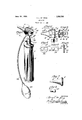
- v Figure l represents a perspective view of an otoscope, embodying my invention.
- Figure 2 represents a section on line of Figure l.
- Figure o represents av perspective view VIl() Lll) ot' the stationary end disc ot the otoscope and the movable shutter coacting therewith, the parts being shown in detached position.
- Figure a represents an end view showing a modilied form ot end disc or shutter support.
- Figure represents a plan view ot a sliding shutter coaeting with thedisc seenin Figure t.
- Figure (3 represents a sectional view ot the disc and shutter seen in Figures d and 5 inassembled position.
- Figure 7 represents a side elevation ot a speculum in detached position.
- Figure 8 represents a side elevation of a detachable tip for said speculum.
- otoscope 1 designates my novel construction of otoscope, the same comprising the handle 2 which serves as a container for a battery, not shown, ot any conventional type or standard type, the top ot said handle having the cover or cap 3 in threaded engagement therewith upon which is mounted the tubular extension l upon which latter is supported the head 5 which is in the term ot a cylinder internally threaded at its front end, as at 6, to receive the externally threaded extension 7 of the speculum 8, which is provided with a body portion having a removable tip 9 and with the knurled tlange 1t), so as to facilitate the engagen'ient and disengagement ot the speculum Awith the head 5.
- the cap 3 is provided with a slot fi() in its top through which passes the switch member 11, whereby the circuit Vis opened and closed so as to illuminate the electric light 12 positioned within the speculum 8.
- the iront end of the otoscope body 5 is shown as being closed by a disc 13 which is provided with the diametrically opposite ports 14, one of said ports as the lett hand one seen in Figure 8 being provided with the lens 15.
- a rotatable shutter which is in the form of a cap closure or disc rotatably mounted against the disc or wall 13 and provided with the pins 17 to enable the shutter to be readily rotated, said shutter being held in assembled position by the flanged ring or annulus 18 which is in threaded engagementJ with the exterior front end portion ot the cylinder 5,
- the shutter 1G is provided with a'pair of ports 19 of substantially the same size as the ports 14 and in one of the ports 19 is secured the lens 20, the construction being such that when the lenses 15.4 and 2O are in alignment the opposite open ports are also in alignment.
- lt will be understood from the Jforegoing that l provide two openings 19 in the outer rotatable member or shutter 16 and also in the stationary underlying member 13 of the head 5 ot the otoscope, and I mount a lens in one ot the openings in each member.
- l. ln an instrument of the character described, a handle, a source of light, a casing, a speculum at one end of the casing and an end cap at the other end, the end cap having a plurality oi openings and an adjustable member also having a plurality of openings, the adjustable member being reta-ined in assembly by peripheral anchorage and a lens mounted in one of the openings of the end cap.
- a handle a source of light, a casing, a speculum at one end of the casing and an end cap at the other end, the end cap having a plurality of openings and an adjustable member also having a plurality of openings and a lensvmounted in one of the openings of both the end cap and the rotatable member.
- an instrument of the character described a handle, a source of light, a cas-4 ing, a speculum at one end of the casing and an end cap at the other end, having a lens and an opening and a cover over the cap having a lens, and means for aligning the lens in the cover with the lens in the cap, or Wit-h the opening, as desired.
Landscapes
- Health & Medical Sciences (AREA)
- Life Sciences & Earth Sciences (AREA)
- Surgery (AREA)
- Nuclear Medicine, Radiotherapy & Molecular Imaging (AREA)
- Biomedical Technology (AREA)
- Optics & Photonics (AREA)
- Pathology (AREA)
- Radiology & Medical Imaging (AREA)
- Biophysics (AREA)
- Engineering & Computer Science (AREA)
- Physics & Mathematics (AREA)
- Heart & Thoracic Surgery (AREA)
- Medical Informatics (AREA)
- Molecular Biology (AREA)
- Animal Behavior & Ethology (AREA)
- General Health & Medical Sciences (AREA)
- Public Health (AREA)
- Veterinary Medicine (AREA)
- Endoscopes (AREA)
Description
June 15 1926..
' y 1,588,791 H. L. DE ZENG oToscoPE Filed June 17, 1922 v l al1/Maia. 2.'. L?
fb f: 9
ATTORNEYS.
Cil
Patented June l5, 1925.
UNITED starts 1,588,791 PATENT GFFlCE.
HENRY L. DE ZENG, OF MOORESTOXVZN', NEW JERSEY, ASSIGLTOR T0 DEZENG STANDARD COMPANY, OF `CAIVIDEN",NEW' JERSEY, A CORPORATIGN OF NEW JERSEY.
OTOSCOPE,
Application led June 17, 1922. Serial No.g568,999.
My invention consists of a novel otoscope for use in examining the external auditory canal and the drumheadof the ear, said otoscope having a magnifying lens and illuminating means for giving an enlarged and better illuminated picture of the visible portions of the ear. It further consists of a novel otoscope having detachable and interchangeable specula, also a pneumatic attachment for use in elfecting certain diagnoses and for massaging the ear, also for aspirating the ear.
` It further consists in an otoscope having the aforesaid advantages in addition to means for permitting the introduction of applicators or instruments through the otoscope to reach the ear, while the otoscope is in place, thus enabling' the surgeon to treat the ear, operate upon the ear, aspirate the ear, make his diagnosis or massage the ear without removing the instrument from the ear, or making any changes in its component parts other than the adjustment of the head portion of the instrument and possible change of speculum.
To the above ends my invention relates more particularly to a novel form of end cap of the otoscope, or that portion nearest to the operator, wherein I provide an inner and an outer disc or shutter which are held in assembly by a threaded ring, the inner disc being stationary and the shutter being movable. Each of these discs has a plurality of openings with a lens mounted in one of the openings of each disc. wWhen -each of the discs'has but two holes, as is the case in the preferred form of my invention, and as the discs are adjustable with respect to each other, a rotation of the outer disc or shutter to that position in which both lenses are in practical alignment, a clear and unobstructed view may be had through the lenses while free access may be had with instruments through the other aligning holes, as when treating or operating upon the ear. To close the otoscope against the -escape of `air, except through the speculum, when the pneumatic attachment is employed, the disc 16 is rotated to bring the lens 2O over the opening in the cap 13, which is not fitted with a lens.
My invention further relates to novel means for holding the speoulum in secure relation with the body portion of the otoscope by means of threaded engagement of said speculum with said body portion, so that said speculum may bequickly detached although firmly held when in operative position.
My invention further consists of a two part speculum wherein the introductory end of the speculum, known as the tip, is detachably connected. This novel feature permits the bell portion of the speculum to remain in assembled position with the otoscopev proper, while one tip may be quickly replaced by one of different size when required, thereby effecting easy manipulations and eXtreme portability also. Then too, the tips may be highly finished internally for the better dissemination of the illuminating raysv from the light source without backreiiections to the eye of the observer. vIn addition the tipsv mayl be quickly and easily sterilized without detriment to the speculum which may now be internally treated down to the point of engagement of the tips, for the prevention of internal reflexes from the lamp.
The speculum being threadably connected with the otoscope in my invention, it does not become loosened, or, as is the casein many instances, become completely detached from the otoscope upon its introduction into the ear. All of the necessary force and oblique movements required to enter a small or irregular canal may now be safely employed without danger of disconnecting the speculum from the otoscope.
llfiy invention further consists of other novel features of construction and advantage, as will be hereinafter described and pointed out in the claims. y
For the purpose of illustrating my invention, I have shownv in the accompanying drawings a form thereof which isv at present preferred by me, since it will give in practice satisfactory and reliable results, although it is to be understood that the various instrinnentalities of which my invention consists can be variously arranged `and organized and that my invention is not limited to the precise arrangement and ort ganization of these instrumentalities as herein shown and described.
vFigure l represents a perspective view of an otoscope, embodying my invention. Figure 2 represents a section on line of Figure l.
Figure o represents av perspective view VIl() Lll) ot' the stationary end disc ot the otoscope and the movable shutter coacting therewith, the parts being shown in detached position.
Figure a represents an end view showing a modilied form ot end disc or shutter support.
Figure represents a plan view ot a sliding shutter coaeting with thedisc seenin Figure t.
Figure (3 represents a sectional view ot the disc and shutter seen in Figures d and 5 inassembled position.
Figure 7 represents a side elevation ot a speculum in detached position.
Figure 8 represents a side elevation of a detachable tip for said speculum.
Similar numerals ot retcrence indicate corresponding parts.
Referring to the drawings,
1 designates my novel construction of otoscope, the same comprising the handle 2 which serves as a container for a battery, not shown, ot any conventional type or standard type, the top ot said handle having the cover or cap 3 in threaded engagement therewith upon which is mounted the tubular extension l upon which latter is supported the head 5 which is in the term ot a cylinder internally threaded at its front end, as at 6, to receive the externally threaded extension 7 of the speculum 8, which is provided with a body portion having a removable tip 9 and with the knurled tlange 1t), so as to facilitate the engagen'ient and disengagement ot the speculum Awith the head 5. The cap 3 is provided with a slot fi() in its top through which passes the switch member 11, whereby the circuit Vis opened and closed so as to illuminate the electric light 12 positioned within the speculum 8.
In the construction seen in Figure 2, the iront end of the otoscope body 5 is shown as being closed by a disc 13 which is provided with the diametrically opposite ports 14, one of said ports as the lett hand one seen in Figure 8 being provided with the lens 15.
16 designates a rotatable shutter, which is in the form of a cap closure or disc rotatably mounted against the disc or wall 13 and provided with the pins 17 to enable the shutter to be readily rotated, said shutter being held in assembled position by the flanged ring or annulus 18 which is in threaded engagementJ with the exterior front end portion ot the cylinder 5, The shutter 1G is provided with a'pair of ports 19 of substantially the same size as the ports 14 and in one of the ports 19 is secured the lens 20, the construction being such that when the lenses 15.4 and 2O are in alignment the opposite open ports are also in alignment.
ln the construction seen in Figures 1, 5 and 6 I have shown the wall 2l which replaces the wall 13 and the cover 16 of Figures 2 and 8 at the trent oit the body 5 as provided with the ports 22 and the parallel ways which are engaged by a laterally movable shutter 2li having a lens 25 therein, said lens being ol" the same character as the lens seen in Figures 1 and 3.
26 designates a handle ot the laterally movable shutter 2a whereby the latter can be readily actuated according to requirements.
In Figures 7 and 8, I have shown in detached position the speculum 8 as being provided with the detachable tip 9, which is shown in detail in Figure 8, and is provided with the tinfeaded portion 9-r so that ditlerent sized tips can be readily engaged with a speculum body ot one standard size.
lt will be understood from the Jforegoing that l provide two openings 19 in the outer rotatable member or shutter 16 and also in the stationary underlying member 13 of the head 5 ot the otoscope, and I mount a lens in one ot the openings in each member.
Vith the lens mounted in the lett hand opening o'l the under member 13 and the lens 2O in the adjustable shutter member 16 positioned in register therewith, an enlarged view of the ear may be had through the left hand opening, while instruments may be introduced through the aligning openings in both the stationary member and the rotatable member, which are then likewise in register on the right hand side. ior treating or operating upon the ear. To close the otoscope against the escape of air when employing the pneumatic attachment comprising the compressible bulb and the tube Sel, the lens in the shutter is turned to the opposite position wherein all openings in the head are closed and no air can escape.
lt will be noticed that in this preferred form ot otoscope embodying my invention, the openings in the head are very close together, which novel arrangement admits of both a lull view through the speculum and full operative or treatment range likewise through the speculum, since in both instances, the lines et observation and application are closely aligned with the axis of the speculum.
It will further be apparent that I employ a novel means for holding the rotatable shutter 16 in assembly, the support tor same in my invention being at the outer periphery and not at the center as in other Jforms of otoscopes, and that by reason of this novel arrangement l am enabled to bring the inner margins of the visual and operating holes in the head of the otoscope into the closest proximity. This arrangement also provides an opportunity of making both holes ot maximum size, thereby giving greater lateral range ot both observation and operating than in any other simlar form of otoscope.
llVhile l have shown my otoscope in its preferred form, nevertheless the lens in the lill) inner or stationary member of the head may be mounted in the hole to the right hand for the admission of a treatment instrument through the lett hand opening and other changes and alterations may be made Within the scope of the claims Without departing from the spirit of my invention.
ln addition to the many advantages contained in my invention already enumerated, it otl'ers extreme portability by son et the employment oi? but one major speculuin S having the interchangeable tips 9 Whereas in all other otoscopes the required sizes of specula can be obtained only in a complete speculum for each size. By this arrangement, it is possible to construct a complet-x otoscope which will require much space in the surgeons hit than would otherwise be possible. rlhe surgeon is also, by reason of my improvement, enabled to mal-ie rapid changes in the speculum sizes and to quickly steriliae the parts actually introduced into the ear. lle is also enabled to see a great deal more by reason of the better dissemination of the light fromthe highly polished walls oi the detachable tips and this is particularly true of all objects lying to that side of the speculum corresponding with the position of the lanp, 0r reilector (as the case may be) With respect to the opening in the speculum Which, of necessity, is placed lateral to the axis of the speculuin or line of direct Observation. i.; lamp being located to one side et the airis oi a speculum, the light proceeds from said lamp to that side of the speculum or speculum tube opposite Vtrom the lamp. From there it is reilected back to the saine side as that ou which the lamp is located, hence lthe side Corresponding with the position oi? the lamp or reflector 'will have increased illumination.
l Having thus described my invention, what l claim as new and desire to secure by Letters latent, is
l. ln an instrument of the character described, a handle, a source of light, a casing, a speculum at one end of the casing and an end cap at the other end, the end cap having a plurality oi openings and an adjustable member also having a plurality of openings, the adjustable member being reta-ined in assembly by peripheral anchorage and a lens mounted in one of the openings of the end cap.
2. ln an instrument of the character describen, a handle, a source of light, a casing, a speculum at one end of the casing and an end cap at the other end, the end cap having a plurality of openings and an adjustable member also having a plurality of openings and a lensvmounted in one of the openings of both the end cap and the rotatable member. l
8. ln an instrument of the character described, a handle, a source of light, a cas-4 ing, a speculum at one end of the casing and an end cap at the other end, having a lens and an opening and a cover over the cap having a lens, and means for aligning the lens in the cover with the lens in the cap, or Wit-h the opening, as desired. ln an instrument of the character described, a handle, a source of light, a casing, a speculuin at one end of the casing and a cap at the other end having a lens and an opening diametricallyV arranged, a cover over the cap having a lens and an opening diametrieally arranged, and peripheral means for securing the cover whereby it may be rotated to bring the lens in the cover in alignment With the lens in the cap or With the opening in the cap, as desired.
HENRY L. DE ZENG.
Priority Applications (1)
| Application Number | Priority Date | Filing Date | Title |
|---|---|---|---|
| US568999A US1588791A (en) | 1922-06-17 | 1922-06-17 | Otoscope |
Applications Claiming Priority (1)
| Application Number | Priority Date | Filing Date | Title |
|---|---|---|---|
| US568999A US1588791A (en) | 1922-06-17 | 1922-06-17 | Otoscope |
Publications (1)
| Publication Number | Publication Date |
|---|---|
| US1588791A true US1588791A (en) | 1926-06-15 |
Family
ID=24273669
Family Applications (1)
| Application Number | Title | Priority Date | Filing Date |
|---|---|---|---|
| US568999A Expired - Lifetime US1588791A (en) | 1922-06-17 | 1922-06-17 | Otoscope |
Country Status (1)
| Country | Link |
|---|---|
| US (1) | US1588791A (en) |
Cited By (4)
| Publication number | Priority date | Publication date | Assignee | Title |
|---|---|---|---|---|
| US3038466A (en) * | 1958-04-28 | 1962-06-12 | Welch Allyn Inc | Orificial instrument construction |
| US3698387A (en) * | 1969-10-07 | 1972-10-17 | Welch Allyn Inc | Otoscope construction |
| USD421123S (en) * | 1998-12-09 | 2000-02-22 | Welch Allyn, Inc. | Speculum for otoscope |
| US20120088976A1 (en) * | 2009-12-30 | 2012-04-12 | Hassan Shehadeh | System and method for suction-assisted object removal |
-
1922
- 1922-06-17 US US568999A patent/US1588791A/en not_active Expired - Lifetime
Cited By (4)
| Publication number | Priority date | Publication date | Assignee | Title |
|---|---|---|---|---|
| US3038466A (en) * | 1958-04-28 | 1962-06-12 | Welch Allyn Inc | Orificial instrument construction |
| US3698387A (en) * | 1969-10-07 | 1972-10-17 | Welch Allyn Inc | Otoscope construction |
| USD421123S (en) * | 1998-12-09 | 2000-02-22 | Welch Allyn, Inc. | Speculum for otoscope |
| US20120088976A1 (en) * | 2009-12-30 | 2012-04-12 | Hassan Shehadeh | System and method for suction-assisted object removal |
Similar Documents
| Publication | Publication Date | Title |
|---|---|---|
| US3586424A (en) | Monocular indirect ophthalmoscope | |
| US4006738A (en) | Otoscope construction | |
| JPS6217042Y2 (en) | ||
| DE69130772D1 (en) | CONTACT LENS SYSTEM FOR INDIRECT EYE DIAGNOSTICS | |
| US2070820A (en) | Laryngoscope | |
| US2039546A (en) | Combination speculum surgical instrument | |
| US1588791A (en) | Otoscope | |
| US1849701A (en) | Speculum | |
| US2023945A (en) | Endoscope | |
| US2182390A (en) | Surgical device | |
| US1618970A (en) | Diagnostic instrument | |
| US3948585A (en) | Ophthalmoscope examination pattern having slit and surrounding ring | |
| US1791604A (en) | Diagnostic instrument | |
| US3861789A (en) | Wide-angle ophthalmoscope | |
| US1795691A (en) | Combined ophthalmoscope, retinoscope, and slit-lamp | |
| US672317A (en) | Speculum. | |
| US1345406A (en) | Mabk cubbon bimmeb | |
| US1608726A (en) | Diagnostic instrument | |
| US1636463A (en) | Otoscope | |
| US1062698A (en) | Auriscope. | |
| US1459313A (en) | Operating urethroscope | |
| US2184414A (en) | Otoscope | |
| US1589172A (en) | Orificial instrument | |
| US1566652A (en) | Optical diagnostic instrument | |
| GB494280A (en) | Improvements in diagnostic optical instruments |