US1586878A - Telegraph system - Google Patents
Telegraph system Download PDFInfo
- Publication number
- US1586878A US1586878A US598539A US59853922A US1586878A US 1586878 A US1586878 A US 1586878A US 598539 A US598539 A US 598539A US 59853922 A US59853922 A US 59853922A US 1586878 A US1586878 A US 1586878A
- Authority
- US
- United States
- Prior art keywords
- cable
- transmitting
- receiving
- segments
- impulse
- Prior art date
- Legal status (The legal status is an assumption and is not a legal conclusion. Google has not performed a legal analysis and makes no representation as to the accuracy of the status listed.)
- Expired - Lifetime
Links
Images

Classifications
-
- H—ELECTRICITY
- H04—ELECTRIC COMMUNICATION TECHNIQUE
- H04L—TRANSMISSION OF DIGITAL INFORMATION, e.g. TELEGRAPHIC COMMUNICATION
- H04L5/00—Arrangements affording multiple use of the transmission path
- H04L5/22—Arrangements affording multiple use of the transmission path using time-division multiplexing
Definitions
- his invention relates to telegrapliy
- Another object of the invention is to provide suitable switching apparatus at the terminals of along submarine cable to autoinatically and alternately associate the transmitters and receivers at the terminal stations with the cable conductors, in such aV manner as to provide the practical equivalent of simultaneous operatic-n in both directions and still permit operation of the system at maxi ⁇ mum efliciency.
- the presenty invention utilizes the same fundamental principle of operation as the Gilbertr system inl whichy the signaling impulses are transmitted over a loaded sub marine cable at relatively low velocity so that an appreciable period of time, for eX- ample, a few' tenthsoffa second, elapses1betweenl the ytime when' the transmitting keyl is closed' and the time' of arrival of the trans mittled impulse at the receiver of the distant station;
- suitable mechanisms are provided for simultaneously and alternatell associafting the transmitters andthe receivers at the terminalA stations with the cable conductor for very short intervals of time which bear a definite relation tothe time required to propaga'tea ⁇ single impulse over the cable.
- l means is' provided for preventing the overlap of receiving and transmitting impulses, suc-limeans also being utilized for curbing the transmitted' impulses.
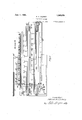
- Fig. l shows the preferred form of apparatus at one lstation of a high speed two-way telegraph system ⁇ adapted for twoecliannel sending and receiving of' signals.
- Fig" 2 shows corresponding segmented rings ofthe dis tributors located' atv the opposite ends of a cable and Figi 3', corresponding to Fig. l, shows the preferredarrangement of apparatusj at the distant end of the cable.
- Each terminal st-ation' is provided with a special rotary distributor, these distributors being" ar “anged to rotate in synchronism in accordance withmeans well known inthe art.
- Each distributor comprises a transmitting section for transmitting' impulses from a transmitting mechanism' to the cable, rareceiifing' section for receiving signals and transferring them to recording' or printing mechanisms., a switch- CII ing section for alternately connecting the transmitting and receiving sections with the cable, and a control section which controls the operation of the transmit-ting and receiving mechanisms in proper secpience.
- the transmitting segments Al to 5 are shown connected in the usual manner to a transmitting mechanism 2l.
- Transmitting segments (i to l() are connect-ed in a similar manner to a second transmitting mechanism
- Receiving segnients ll to 15 are connected to a printing mechanism 23 and receiviniv segments i6 to 20 are connected to a similar printing mechanism 24.
- a brush member 30 mounted on a rotatable brush arm 3l is adapted to successively engage segments l to l() and connect them with a transmitting ring T, which in turn is connected through the winding oi' a curbingrelay and condenser to a corresponding series ot segments i() to 49.
- the segments Ll() to e9 are of the same length as segments l. to l() and are in align-l ment therewith on the distributor.
- the receiving segments 1S t0 2O and 1l to 17 are connected successivelyv to a solid ring section R which is connected to the armature ot' the line relay 35, which in its operated position is connected to a grounded source ot energy 36.
- the winding of relay 35 is connected through a shaping network 37 to receiving segments to 59 on the switching section ot the distributor. These segments correspond in length and position to the receiving segments 1S to 2O and il to 17.
- Positioned between the transmitting and receiving segments ot the switching section are the curbing segments Gil-60 which are connected through the curbing condenser 6l to the armature ot curbing relay 25.
- the brush member 33 By means ot the brush member 33, the transmitting segments ll() to 49, receiving sogments 50 to 5i? and the curbing segments (SO- are connected with the ring .member S which is connected to the cable C through a lengthening network (52, the purpose ot' which will be explained hereinafter.
- the fourth section oit the distributor comprises a solid ring member L which is connected to a grounded source oi energy G3 and active segments Gil, 65, G6 and 6T. Segment is connected to the tape advancing electromagnet 68 of transmitter 22; segment is connected to the operating magnet G9 ot printing mechanism 24; segment 6G is connected to the tape advancing electromagnet .70 of transmitter 2l; and segment 67 is connected to the operating magnet 7l of printing mechanism 23.
- a brush member Se also mounted on the rotatable brush arm 8l serves to connect local segments Gi to 6i' with the ring L in proper order to canse the operation ot the printing and transmitting mechanisms in the correct sequence.
- rlhe operation oi' relay 35 causes the impulse to be transmitted from the grounded source ot energy 3G through thearinature ot relay 35 to ring R', thence through brush 32 to receiving segment il which is connected to the printing mechanism 23.
- oi' relay 35 causes the impulse to be transmitted from the grounded source ot energy 3G through thearinature ot relay 35 to ring R', thence through brush 32 to receiving segment il which is connected to the printing mechanism 23.
- due to brush SO at station A wiping over transmitting segments 2, 3, 4i and 5 impulses are received at station ll on segments l2', 13', le and l5 and operate the respective electromagnets ot printer 23 to set up the predetermined character.
- the brush member 3i Upon further rotation of the brush arm carrying brush 33', the brush member 3i connects local segment G7 with the ring member L thus coi'npleting a circuit from the grounded source ot energy 63 through ring member L, brush Se', local segment 6? and operating magnet T1 to cause the operation ot' the printing mechanism.
- each current impulse at that terminal said switching means being driven in synchronism and arranged to provide .simultaneous trai'ismission and simultaneous reception at the terminal stations.
- each et said terminal stations including a transmitting mechanism, a receiving mechanism and a ⁇ rotary distributor', said distributors being driven in synchronism and each including a transmitting section, a receiving section, a switching section for alternatelv connecting said transmitting and receiving (tions to the cable after the transmission or reception et each signal impulse over the cable, and a control section tor controlling the operation ot' the receiving and transmitting mechanisms.
- Li. ln a telegraph system a cable, and a pair et terminal stations connected to the ends thereoi, each ot said terminal stations including a transmitting mechanism, a receiving mechanism and a rotary distributor, said distributors being driven in synchronism and each including a transmitting seetion, a receiving section, and a combined switching and curbing section for alternately connecting the transmitting and receiving sections with the cable and tor curbing the impiiilses transmitted over the line.
- each ot said terminal stations including a transmitting mechanism, a receiving mechanism and a rotary distribuitor, said distributors being driven in syn chronism and each including a transmitting section, a receiving section, and a switching section 'for alternately associating the transmitter and receiver of that terminal .
- ln telegraph system a loaded cable, and a pair ot terminal stations connected to the ends thereof, Veach ci said terminal stations comprising a transmitting mechanism, a receiving mechanism, and switching means alternately associating the transmitting mechanism and the receiving mechanism with the cable, the time represented by a plurality ot successive transmitting and receiving periods being equal to the time required tor a signal impulse transmitted from one station to arrive at the receiver of the other station.
- a telegraph system a cable and a paii ⁇ ot terminal stations connected t-o the ends thereof, each et said terminal stations comprising a transmit-ting mechanism, a receiving mechanism, and automatic means for associating either the transmitting mechanism or the receiving mechanism alternately With the cable after the transmission or reception of each impulse over the cable.
- ln atelee'ra )h s istem a cable. a lenOthening network connected thereto, and a pair ot terminal stations connected to the ends ot the cable, each ot said terminal stations comprising a transmitting mechanism, a receiving mechanism, and switching means for alternately associating the transmitting mechanism and the receiving mechanism vvvith the cable, the time represented by a plurality ot alternate transmitting and receiving' periods being equal to the time required tor a single impulse to travel over the cable and the lengthening network'.
- a method of two-way signaling betuf'een two stations which consists in alternately siniultaneously transmitting and simultaneously receiving at both stations, said change trom transmitting to receiving, or vice versa, taking place after the transmis sion or reception et each signal impulse.
- A. method ot' two-Way signaling between tivo stations which consists in both stations simultaneously transmitting and receiving alternate signal impulses over a cable at a trequency having a definite relation to the time ot propagation of a current impulse over the cable.
- a method ot'two-way signaling betu'een tivo stations which consist-s in both stations sin'iultaneously transmitting an impulse over the cable, sending out a curbing impulse, and then receiving a current impulse, the period ot alternately transmitting and receiving a group ot current impulses being equal to the time ot propagation ot a current impulse over the cable.
- AL method ot twofmy signaling over a conductor Which has an appreciable propagation period and is provided With means tor operatively associating it with both transmitters simultaneously and disassociating it from them and tor operatively asso ciating said conductor with both receivers, which method comprises operating said means to associate the transmitters with the cable to transmit a single impulse, disasseeiating said transmitters trom the cable and transmitting a curbing impulse thereover, associating the receivers with the cable to receive a single impulse and then disassociat ⁇ ing the receivers trom the cable, the speed ot operation ot said means being such that the time required tor a plurality ot trans mitting, curbing and receiving periods is equal to that timeot propagation ot a single impulse over the cable.
Landscapes
- Engineering & Computer Science (AREA)
- Signal Processing (AREA)
- Computer Networks & Wireless Communication (AREA)
- Cable Transmission Systems, Equalization Of Radio And Reduction Of Echo (AREA)
Description
June 1 1926.
A. A.CLQKEY yTELEGRAPH `SYSTEM* 2 Sheets-Sheet 2 m. Sorg@ /n Ven for.' A//LS on A. C/oke y by A/j/ l Elli Patented .lune 1, 1926.
i ara ALLSOIil" A. CLOKEY, GF RUIHERFORD, NEW JERSEY, ASSIGNOR 'iO WESTERN ELEG- Tnrc coa/trama', ruconrona'rnn, or new Yoan,
YORK.
A CGRPORATIO OF NEW Tnrinerrtei-H- 'svsrnivt apprise-una inea Novembre 2, ieee.- seriar No: 593,539.
'l1 his invention relates to telegrapliy, and
particularly to a method and system of high tions where itv is impossible to employ the ordinary duplex method of operation, in which it is necessary to maintain al very ac'- curate balance.
Another object of the invention is to provide suitable switching apparatus at the terminals of along submarine cable to autoinatically and alternately associate the transmitters and receivers at the terminal stations with the cable conductors, in such aV manner as to provide the practical equivalent of simultaneous operatic-n in both directions and still permit operation of the system at maxi` mum efliciency.
ln my copending application Serial No.' '592,010, filed October 3, 19:22, there is dis'- closed a .somewhat similar telegraph system' designed to accomplish practically thesame objects. The present invention, however, re'- lates to an improvement over the `previous system in that it .makes possible the opera# tion of a telegraph system over along submarine cable at its maximum efhciency by operating the terminal apparatus at4 the' highest speed permitted by the characterise' tics of the cable.-
Ordinary submarine cables are not adapted to high speed signaling because of distortion of the signaling impulses due to the large distributed capacity ofthe cable conductors. ln view of themany diiliculties to be overcome, it has not been the practice to w inductively load such cables to overcome the effect of the large distributed capacity.
However, by the use ofl a certain niclelironj alloy, which has appropriately been termed "permalloy,7 when properly prepared and ciently accurate balance to permit duplex` operation.
lloi'vever, when trans-v I, ln an application ofy John I. Gilbert, filed Mayr 15, 1922,. clerial No.'561',l38,there is described' a; method of two way operation which doesv not depend upon the conjugate relationshipE of transmitter and receiver as does' the ordinary duplex method of operation; The presenty invention utilizes the same fundamental principle of operation as the Gilbertr system inl whichy the signaling impulses are transmitted over a loaded sub marine cable at relatively low velocity so that an appreciable period of time, for eX- ample, a few' tenthsoffa second, elapses1betweenl the ytime when' the transmitting keyl is closed' and the time' of arrival of the trans mittled impulse at the receiver of the distant station;
ln accordance with a feature of the present invention, suitable mechanisms are provided for simultaneously and alternatell associafting the transmitters andthe receivers at the terminalA stations with the cable conductor for very short intervals of time which bear a definite relation tothe time required to propaga'tea` single impulse over the cable. ln accordance with another feature of the inventionl means is' provided for preventing the overlap of receiving and transmitting impulses, suc-limeans also being utilized for curbing the transmitted' impulses.
These and other features ofthe inventionl will be more clearly understood' by reference to the accompanying drawing in whichFig. l shows the preferred form of apparatus at one lstation of a high speed two-way telegraph system` adapted for twoecliannel sending and receiving of' signals. Fig", 2 shows corresponding segmented rings ofthe dis tributors located' atv the opposite ends of a cable and Figi 3', corresponding to Fig. l, shows the preferredarrangement of apparatusj at the distant end of the cable.
Referring now to the drawing there is disclosed a telegraph system consisting` of terminal stations A and B' joined by the cable C. Each terminal st-ation'is provided with a special rotary distributor, these distributors being" ar "anged to rotate in synchronism in accordance withmeans well known inthe art. Each distributor comprises a transmitting section for transmitting' impulses from a transmitting mechanism' to the cable, rareceiifing' section for receiving signals and transferring them to recording' or printing mechanisms., a switch- CII ing section for alternately connecting the transmitting and receiving sections with the cable, and a control section which controls the operation of the transmit-ting and receiving mechanisms in proper secpience.Y
In the arrangement as illustarted two channels are provided tor the transmission'and the reception of impulses. The number or' channels to be employed for etiicient operation depends upon the maximum speed obtainable with the printing and transniiitting mechanisms since it is desirable to operate the cable at its maximum etticiency.
At terminal station A, shown on Fig. 1 ot the drawing, the transmitting segments Al to 5 are shown connected in the usual manner to a transmitting mechanism 2l. Transmitting segments (i to l() are connect-ed in a similar manner to a second transmitting mechanism Receiving segnients ll to 15 are connected to a printing mechanism 23 and receiviniv segments i6 to 20 are connected to a similar printing mechanism 24. A brush member 30 mounted on a rotatable brush arm 3l is adapted to successively engage segments l to l() and connect them with a transmitting ring T, which in turn is connected through the winding oi' a curbingrelay and condenser to a corresponding series ot segments i() to 49. The segments Ll() to e9 are of the same length as segments l. to l() and are in align-l ment therewith on the distributor.
By means ot a second brush men'iber 32 mounted on the brush arm 3l, the receiving segments 1S t0 2O and 1l to 17 are connected successivelyv to a solid ring section R which is connected to the armature ot' the line relay 35, which in its operated position is connected to a grounded source ot energy 36. The winding of relay 35 is connected through a shaping network 37 to receiving segments to 59 on the switching section ot the distributor. These segments correspond in length and position to the receiving segments 1S to 2O and il to 17. Positioned between the transmitting and receiving segments ot the switching section are the curbing segments Gil-60 which are connected through the curbing condenser 6l to the armature ot curbing relay 25. By means ot the brush member 33, the transmitting segments ll() to 49, receiving sogments 50 to 5i? and the curbing segments (SO- are connected with the ring .member S which is connected to the cable C through a lengthening network (52, the purpose ot' which will be explained hereinafter.
The fourth section oit the distributor comprises a solid ring member L which is connected to a grounded source oi energy G3 and active segments Gil, 65, G6 and 6T. Segment is connected to the tape advancing electromagnet 68 of transmitter 22; segment is connected to the operating magnet G9 ot printing mechanism 24; segment 6G is connected to the tape advancing electromagnet .70 of transmitter 2l; and segment 67 is connected to the operating magnet 7l of printing mechanism 23. A brush member Se also mounted on the rotatable brush arm 8l serves to connect local segments Gi to 6i' with the ring L in proper order to canse the operation ot the printing and transmitting mechanisms in the correct sequence.
lliith station B equipped in a similar manner to station and assuming the brush arms to be driven in synchronism so that the brushes advance at a uniform speed over the developed distributor sections, the operation oi' the system is believed to be at once apparent. As brush 3l) connects segment l to transmitting ring 'i an impulse is transmitted 'from the transmitter 2i through segment l, brush 230, ring T, the winding ot curbing` relay 25, transmitting condenser 2G to transmitting segment 4l() oit the switching section. Since brush advances uniformly with brush 30 the circuit is extended from segment -iO through brush 33, ring S, and lengthening network 62 to cable C.
Due to the characteristics of the cable, appreciable time elaspes before the signal propagated at station A arrives at station B. In the present case, as will be seen by referring to 2, it has been assumed that this period ot time will be suoli that the brushes have advanced to the point X-X and are just engaging with receiving segments ll-ll. rlhe impulse therefore transmitted from segment l at station A upon reaching station B passes through the lengthening network G2v to ring member S ot the switching section, is transmitted through brush member 33 to segment 53 and thence through the shaping network 3T and relay 35 to ground. rlhe operation oi' relay 35 causes the impulse to be transmitted from the grounded source ot energy 3G through thearinature ot relay 35 to ring R', thence through brush 32 to receiving segment il which is connected to the printing mechanism 23. In a similar manner, due to brush SO at station A wiping over transmitting segments 2, 3, 4i and 5 impulses are received at station ll on segments l2', 13', le and l5 and operate the respective electromagnets ot printer 23 to set up the predetermined character. Upon further rotation of the brush arm carrying brush 33', the brush member 3i connects local segment G7 with the ring member L thus coi'npleting a circuit from the grounded source ot energy 63 through ring member L, brush Se', local segment 6? and operating magnet T1 to cause the operation ot' the printing mechanism.
During the interval that an impulse is being transmitted trom segment l, the windlli) Iii)
each current impulse at that terminal, said switching means being driven in synchronism and arranged to provide .simultaneous trai'ismission and simultaneous reception at the terminal stations.
3. In a telegraph systeni a cable and a pair ott terminal stations connected to thel ends thereo'ii, each et said terminal stations including a transmitting mechanism, a receiving mechanism and a` rotary distributor', said distributors being driven in synchronism and each including a transmitting section, a receiving section, a switching section for alternatelv connecting said transmitting and receiving (tions to the cable after the transmission or reception et each signal impulse over the cable, and a control section tor controlling the operation ot' the receiving and transmitting mechanisms.
Li. ln a telegraph system a cable, and a pair et terminal stations connected to the ends thereoi, each ot said terminal stations including a transmitting mechanism, a receiving mechanism and a rotary distributor, said distributors being driven in synchronism and each including a transmitting seetion, a receiving section, and a combined switching and curbing section for alternately connecting the transmitting and receiving sections with the cable and tor curbing the impiiilses transmitted over the line.
5. ln a telegraph system a loaded cable,
and a pair ot terminal stations connected to 'he ends thereof, each ot said terminal stations including a transmitting mechanism, a receiving mechanism and a rotary distribuitor, said distributors being driven in syn chronism and each including a transmitting section, a receiving section, and a switching section 'for alternately associating the transmitter and receiver of that terminal .viththe cable after the transmission or recepti on yot' each signal impulse over the cable and tor periods ot' time bearing an exact relationship with the time required for a signal transmitted from one station to arrive at the receiver of the other station.
ln telegraph system a loaded cable, and a pair ot terminal stations connected to the ends thereof, Veach ci said terminal stations comprising a transmitting mechanism, a receiving mechanism, and switching means alternately associating the transmitting mechanism and the receiving mechanism with the cable, the time represented by a plurality ot successive transmitting and receiving periods being equal to the time required tor a signal impulse transmitted from one station to arrive at the receiver of the other station.
7. ln a telegraph system a cable and a paii` ot terminal stations connected t-o the ends thereof, each et said terminal stations comprising a transmit-ting mechanism, a receiving mechanism, and automatic means for associating either the transmitting mechanism or the receiving mechanism alternately With the cable after the transmission or reception of each impulse over the cable.
8. ln atelee'ra )h s istem a cable. a lenOthening network connected thereto, and a pair ot terminal stations connected to the ends ot the cable, each ot said terminal stations comprising a transmitting mechanism, a receiving mechanism, and switching means for alternately associating the transmitting mechanism and the receiving mechanism vvvith the cable, the time represented by a plurality ot alternate transmitting and receiving' periods being equal to the time required tor a single impulse to travel over the cable and the lengthening network'.
9. A method of two-way signaling betuf'een two stations which consists in alternately siniultaneously transmitting and simultaneously receiving at both stations, said change trom transmitting to receiving, or vice versa, taking place after the transmis sion or reception et each signal impulse.
l0. A. method ot' two-Way signaling between tivo stations which consists in both stations simultaneously transmitting and receiving alternate signal impulses over a cable at a trequency having a definite relation to the time ot propagation of a current impulse over the cable.
ll. A method ot'two-way signaling betu'een tivo stations which consist-s in both stations sin'iultaneously transmitting an impulse over the cable, sending out a curbing impulse, and then receiving a current impulse, the period ot alternately transmitting and receiving a group ot current impulses being equal to the time ot propagation ot a current impulse over the cable.
12. AL method ot twofmy signaling over a conductor Which has an appreciable propagation period and is provided With means tor operatively associating it with both transmitters simultaneously and disassociating it from them and tor operatively asso ciating said conductor with both receivers, which method comprises operating said means to associate the transmitters with the cable to transmit a single impulse, disasseeiating said transmitters trom the cable and transmitting a curbing impulse thereover, associating the receivers with the cable to receive a single impulse and then disassociat` ing the receivers trom the cable, the speed ot operation ot said means being such that the time required tor a plurality ot trans mitting, curbing and receiving periods is equal to that timeot propagation ot a single impulse over the cable.
In Witness whereof, l hereunto subscribe my name this 31st day ot Uetober A. D., 1922.
ALLISON A. CLOKEY.
Priority Applications (1)
| Application Number | Priority Date | Filing Date | Title |
|---|---|---|---|
| US598539A US1586878A (en) | 1922-11-02 | 1922-11-02 | Telegraph system |
Applications Claiming Priority (1)
| Application Number | Priority Date | Filing Date | Title |
|---|---|---|---|
| US598539A US1586878A (en) | 1922-11-02 | 1922-11-02 | Telegraph system |
Publications (1)
| Publication Number | Publication Date |
|---|---|
| US1586878A true US1586878A (en) | 1926-06-01 |
Family
ID=24395962
Family Applications (1)
| Application Number | Title | Priority Date | Filing Date |
|---|---|---|---|
| US598539A Expired - Lifetime US1586878A (en) | 1922-11-02 | 1922-11-02 | Telegraph system |
Country Status (1)
| Country | Link |
|---|---|
| US (1) | US1586878A (en) |
-
1922
- 1922-11-02 US US598539A patent/US1586878A/en not_active Expired - Lifetime
Similar Documents
| Publication | Publication Date | Title |
|---|---|---|
| US1586878A (en) | Telegraph system | |
| US1601940A (en) | Telegraph system | |
| US1752485A (en) | Secrecy system | |
| US1601941A (en) | Submarine telegraph system | |
| US1586895A (en) | Submarine-cable signaling | |
| US1631976A (en) | Signaling | |
| US1832308A (en) | Interpolating system | |
| US1695040A (en) | Multiplex-telegraph system | |
| US1386679A (en) | Telegraph system | |
| US2057680A (en) | Receiving channel assigner | |
| US1812635A (en) | Signaling system | |
| USRE18126E (en) | Phone labqsatokies | |
| US1657384A (en) | Telegraph system | |
| US1858237A (en) | Submarine cable telegraph system | |
| US1992220A (en) | Interpolating receiving system | |
| US1835281A (en) | Regenerative cable repeater for telegraph systems | |
| US2174221A (en) | Telegraph signaling repeater | |
| US1817989A (en) | Connection for telegraph plants | |
| US1245507A (en) | Telegraph system. | |
| US704928A (en) | Telegraphic distribution. | |
| US1664453A (en) | Manual morse multiplex system | |
| US1617993A (en) | Multiplex-channel repeater system | |
| US1965347A (en) | Direction control, switch for signaling systems | |
| US1522865A (en) | Signaling system | |
| US1362592A (en) | Telegraph system |