US1581237A - Telephone receiver - Google Patents
Telephone receiver Download PDFInfo
- Publication number
- US1581237A US1581237A US604703A US60470322A US1581237A US 1581237 A US1581237 A US 1581237A US 604703 A US604703 A US 604703A US 60470322 A US60470322 A US 60470322A US 1581237 A US1581237 A US 1581237A
- Authority
- US
- United States
- Prior art keywords
- casing
- magnet
- coils
- coil
- extending
- Prior art date
- Legal status (The legal status is an assumption and is not a legal conclusion. Google has not performed a legal analysis and makes no representation as to the accuracy of the status listed.)
- Expired - Lifetime
Links
Images

Classifications
-
- H—ELECTRICITY
- H04—ELECTRIC COMMUNICATION TECHNIQUE
- H04R—LOUDSPEAKERS, MICROPHONES, GRAMOPHONE PICK-UPS OR LIKE ACOUSTIC ELECTROMECHANICAL TRANSDUCERS; ELECTRIC HEARING AIDS; PUBLIC ADDRESS SYSTEMS
- H04R13/00—Transducers having an acoustic diaphragm of magnetisable material directly co-acting with electromagnet
- H04R13/02—Telephone receivers
Definitions
- .TlllS invention relates to telephone. re DCAm, particularly to the 'watch case type such as are most frequently used in radio telephony. p
- one of the objects of my 111.- vention is to so construct the permanent magnet that it comprises a single easily positioned piece and likewise the electro-mag netic coils and cores comprise an assembled unit completed outside the casing adapted to complete its rmagnetlc and circuit connections by simply' placing itin position, thus avoiding an ation within the'caSing...
- my invention provides for a permanent magnet construction which occupies a minimum space.
- the magnet construction contemplated permits the receiver to be readily dismantled'and the magnet to be replaced without affecting the electrical connections between the coils and the leads extendingtherefrom.
- I employ the usual casing, a diaphragm and ear piece with electrical connections leading from the exterior of the casing to the interior thereof.
- I provide an endless permanent magnet having opposed pole pieces and I provide coils having the cores -marized inthe claims;
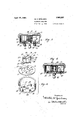
- r In the draw1ngs,'F1g. l- is an end view of ings, and the essential features will be"sum-- a receiver embodying my invention and showing the provision for attachment of a head strap;
- Figs. 4 and 5 are sec- [310113011 the llnes H and 55 respectively,
- FIG. '3 and Fig. 6 is a perspective View showing the relative" position for assembling of the various vention.
- 10' indicates a casing having a diaphragm 11,
- I provide anendless pere manent magnet, indicated at 13,-and a coil 14 positioned thereabove.
- the permanent magnet is shown as comprising. anannular member having opposed pole pieces 15 and 16 extending lnwardly' and formed integral with the ring-like body of the magnet.
- This magnet' may be a metallic stamping, which is hardened in the usual manner and fitting closely in the side wall of the casing,flyingflat against the bottom or rear wallthereof. Suitable openings 17 and 18 extend through the magnet for receiving clamping screws 19 and 20.
- Thecoil and pole piece extensions comprise a single unitary structure which is readily adapted for attachment 1 mechanically and electrically within the casing.
- Each extension member constitutesthe core of a coil, and is adapted to be attached to the magnet by the same securing members employed for retaining the magnet within parts, as set forth in myinthe casing.
- each core as comprising an L-shaped member, one arm of which, as at 25 and 26, extends through the coils and other arms, as at 27 and 28, engage the magnet, as illustrated in Fig. 4.
- the terminals from the coil lead outwardly and are electrically connected to contact members in the nature of eyelets 29 and 30 which are shown as flanged to embrace a flexible base extending transversely of the pieces 27 and 28.
- This base is formed of insulating material, such as fibre, and is adapted to fit over the upwardly extending arms ot the pole extensions.
- a suit able non-magnetic spacing member 36 extends over the ends of the arms 25 and 26 closely embracing the same and maintains the coils permanently in position.
- the magnetic core and arms are each preterably made of soft magnet core iron andas the flat portions 27 and 28 may fit closely upon the pole pieces ot the permanent magnet, magnetic flux is established through these elements, which rluX may be varied in the usual way by the action of the electromagnetic coils to vibrate the diaphragm 11.
- the small wire terminals ot the coils may be conveniently electrically connected to the eyelets 29 and 30 by simply soldering them or clamping the wire beneath the edge thereof, forming a permanent electrical connection which need not thereafter be disturbed; these eyelets later forming connection by simply pressing against binding posts which will be described.
- the coil and extension pieces are assembled, as shown in Eig. (3, openings 21 and 22 in the core arms are in registration with the openings 17 and 18 in the permanent magnet. Accordingly, the eyelets 29 and 30 are in position to engage contact members 37 and 38 which are shown as bindscrews eitending through the casing on a line transversely of the attaching screws 19 and 20. Suitable washers 40 may be placed beneath the heads of the contact members 37 and 38 to cause an upward pressure to be exerted against the under surface of the eyelets, whereby the inherent resiliency in the base maintains an electrical circut through the coil. In this way, the coil may be readily assembled outside the casing and then connected electrically with the connections leading into the casing, when the extension pieces are attached to the "fastenin members 19 and 20.
- i have shown my invention as adapted for use in radio telephony wherein two receivers n'iay be mounted on a head strap 50.
- the nanner of mounting embodied in a bracket 51 which straddles the casing and is pivoted on suitable trunnions 52 associated with the exterior or the casing.
- a spindle 53 may be rigidly secured to the intermediate portion of the bracket and is adapted to carry the ends of the head strap.
- I have shown the end of the strap as having an apertured member 54 which engages the spindle and is loosely mounted thereon.
- a spring 55 also having an opening therein which fits over the spindle, is rigidly attached to the strap in such manner as to extend at an angle therefrom, as indicated in Fig. 1.
- the inherent resiliency ot the spring, and the inclination from the strap is such that the spindle is gripped with sullicient force to retain the strap in any desired position.
- the spring and member 54 are pressed together, whereupon the spindle may be moved in either direction relatively to the strap.
- the spring is released, whereupon the spindle is gripped in a new position.
- the magnet is placed within the casing with the openings 17 and 18 extending over the attaching screws 19 and 20, and then the coil is positioned within the casing with the openings 21 and 22 in the extensions in registration with the openings in the magnet. This brings the extension pieces into engagement with the pole pieces.
- the attaching men'ibers 19 and 20 are tightened, the eyelets 29 and 30 with which the leads from the coils are elcc trically connected, are brought into engagement with the contact members 37 and 38, which extend through the casing at points equidistant from the screws 19 and 20. Then the electrical connection is completed by attaching wires and 61 outside the casing.
- coils having the cores thereot shaped to rest I on the sole 31GCQS and to rovide extensions net, means for removably securing the coils within the casing, electrical conductors extending through the casing, remote from the magnet connections to the'casing'and means for automaticallv eit'ectin electrical contact u h between the leads from the coil and said con ductors when the coils are positioned within.
- a device of the class describechthe combination with a casing,ot' a magnet carried thereby, a coil having the cores thereof extending along and; resting on said magnet, electrical connections extending through the casing, and flexible means carried by the coil and supporting coil terminal contacts for eliiecting electricaleontact between the coils and connections.
- a device of the class described the I combination with a casing, of a one-piece magnet carried thereby, said magnet having inwardly extending pole pieces thereon, coils associated therewith, the cores of said coils extending laterally in opposite directions, and are adapted to rest upon said pole pieces, a flexible base of insulating material projecting laterally from the coil and transversely of said core extensions, said base carrying the leads from said coils, electrical contact pieces associated with the casing, and means whereby contact of the core'extensions and magnet effects an interengagement of the leads from the coil with said contact pieces.
- the cores of which comprise feet resting on the pole pieces, and a base for the coil,-'said base carrying contact members which are adapted to engage the conductors for completing an electrical circuit through the conductors and coil when the coresof the coil are attachedto the magnet.
Landscapes
- Physics & Mathematics (AREA)
- Electromagnetism (AREA)
- Engineering & Computer Science (AREA)
- Acoustics & Sound (AREA)
- Signal Processing (AREA)
- Magnetic Treatment Devices (AREA)
Description
April 20,1926. v 1,581,237
. -M. H. SPIELMAN TELEPHONE RECEIVER vFiled Dec. 4. 1922 2- Sheets-Sheet 1 5 l\ 26 U I y 1h; \\l"""' JZIYEHTOR April 20-, 1926. 1581237 M. H. SPIELMAN TELEPHONE RECEIVER a Filed Dec. 4', 1922 2 Sheets-Sheet 2 all A fvymgtz'oji Q .WJQRW .ATTYS.
Patented Apr.. 20, 1926.
4 UNITEDSTAITES,
MILTON H. SPIELMAN, or CLEVELAND, on r hsslenon TO THE noMEs'rIo ELECTRIC PATENTAOFFICE.
COMPANY, OF CLEVELAND, OHIO A CORPORATION OF OHIO.
TEL PHonE RECEIVER,
App licationfiled December 4, 1922. Serial No. 4,703; i
To all whom it may concern.
Be it knownthat I, MILTON H. SPIELMAN, a citizen of the United States residing at Cleveland, in the county'of Guyahoga and State of Ohio, have invented a certain new and useful Improvement in Telephone R eceivers, of which the following'is a full,
clear, and exact description,referencebeing had t9 the accompanying drawings.
.TlllS invention relates to telephone. re ceivers, particularly to the 'watch case type such as are most frequently used in radio telephony. p
In the manufacture of watch case receivers, considerable difficulty has heretofore been experienced in assembling the permanent magnet member and associated coils. One of the causes of these difliculties is the small space within which the parts must be assembled, and the degree of accuracy which must be used to provide and maintain an electrical circuit through the resistance coils.
I have found that soldering leads from the coils to electrical connections extending through the casing, necessitates considerable time.
Accordingly one of the objects of my 111.- vention is to so construct the permanent magnet that it comprises a single easily positioned piece and likewise the electro-mag netic coils and cores comprise an assembled unit completed outside the casing adapted to complete its rmagnetlc and circuit connections by simply' placing itin position, thus avoiding an ation within the'caSing...
Other objects include thearrangenient of a unitary coil structure whereby replacement thereof may be readily accomplished withy soldering oper out necessitating replacement of a complete In addition, my invention provides for a permanent magnet construction which occupies a minimum space. The magnet construction contemplated, permits the receiver to be readily dismantled'and the magnet to be replaced without affecting the electrical connections between the coils and the leads extendingtherefrom. a
In carrying out my invention, I employ the usual casing, a diaphragm and ear piece with electrical connections leading from the exterior of the casing to the interior thereof. Within the casing, I provide an endless permanent magnet having opposed pole pieces and I provide coils having the cores -marized inthe claims; r In the draw1ngs,'F1g. l-is an end view of ings, and the essential features will be"sum-- a receiver embodying my invention and showing the provision for attachment of a head strap; Fig. 2 is a rear view of the re 7 ceiver shown in Fig. vlyhig. 3 is a plan Viewof the receiver having the ear piece and diaphragm removed; Figs. 4 and 5 are sec- [310113011 the llnes H and 55 respectively,
in Fig. '3 and Fig. 6 is a perspective View showing the relative" position for assembling of the various vention.
Designating the parts shown in the drawings by the use of reference characters, 10' indicates a casing having a diaphragm 11,,
and an ear piece 12 associated therewith.
Within the casing, I provide anendless pere manent magnet, indicated at 13,-and a coil 14 positioned thereabove. The particular con-- struction of the magnet and coil, together with the'manner of connection to the casing,
embody particular features of my invention as will now be described.
.The permanent magnet is shown as comprising. anannular member having opposed pole pieces 15 and 16 extending lnwardly' and formed integral with the ring-like body of the magnet. -This magnet'may be a metallic stamping, which is hardened in the usual manner and fitting closely in the side wall of the casing,flyingflat against the bottom or rear wallthereof. Suitable openings 17 and 18 extend through the magnet for receiving clamping screws 19 and 20.
Thecoil and pole piece extensions comprise a single unitary structure which is readily adapted for attachment 1 mechanically and electrically within the casing. Each extension member constitutesthe core of a coil, and is adapted to be attached to the magnet by the same securing members employed for retaining the magnet within parts, as set forth in myinthe casing. To this end, I have shown each core as comprising an L-shaped member, one arm of which, as at 25 and 26, extends through the coils and other arms, as at 27 and 28, engage the magnet, as illustrated in Fig. 4.
The terminals from the coil lead outwardly and are electrically connected to contact members in the nature of eyelets 29 and 30 which are shown as flanged to embrace a flexible base extending transversely of the pieces 27 and 28. This base is formed of insulating material, such as fibre, and is adapted to fit over the upwardly extending arms ot the pole extensions. A suit able non-magnetic spacing member 36 extends over the ends of the arms 25 and 26 closely embracing the same and maintains the coils permanently in position.
The magnetic core and arms are each preterably made of soft magnet core iron andas the flat portions 27 and 28 may fit closely upon the pole pieces ot the permanent magnet, magnetic flux is established through these elements, which rluX may be varied in the usual way by the action of the electromagnetic coils to vibrate the diaphragm 11. The small wire terminals ot the coils may be conveniently electrically connected to the eyelets 29 and 30 by simply soldering them or clamping the wire beneath the edge thereof, forming a permanent electrical connection which need not thereafter be disturbed; these eyelets later forming connection by simply pressing against binding posts which will be described.
hen the coil and extension pieces are assembled, as shown in Eig. (3, openings 21 and 22 in the core arms are in registration with the openings 17 and 18 in the permanent magnet. Accordingly, the eyelets 29 and 30 are in position to engage contact members 37 and 38 which are shown as bindscrews eitending through the casing on a line transversely of the attaching screws 19 and 20. Suitable washers 40 may be placed beneath the heads of the contact members 37 and 38 to cause an upward pressure to be exerted against the under surface of the eyelets, whereby the inherent resiliency in the base maintains an electrical circut through the coil. In this way, the coil may be readily assembled outside the casing and then connected electrically with the connections leading into the casing, when the extension pieces are attached to the " fastenin members 19 and 20.
i have shown my invention as adapted for use in radio telephony wherein two receivers n'iay be mounted on a head strap 50. The nanner of mounting embodied in a bracket 51 which straddles the casing and is pivoted on suitable trunnions 52 associated with the exterior or the casing. A spindle 53 may be rigidly secured to the intermediate portion of the bracket and is adapted to carry the ends of the head strap. To secure adjustment, I have shown the end of the strap as having an apertured member 54 which engages the spindle and is loosely mounted thereon. A spring 55 also having an opening therein which fits over the spindle, is rigidly attached to the strap in such manner as to extend at an angle therefrom, as indicated in Fig. 1. The inherent resiliency ot the spring, and the inclination from the strap is such that the spindle is gripped with sullicient force to retain the strap in any desired position. To adjust the receiver, the spring and member 54; are pressed together, whereupon the spindle may be moved in either direction relatively to the strap. when the desired adjustment is obtained, the spring is released, whereupon the spindle is gripped in a new position.
To assemble the receiver in accordance with my invention, the magnet is placed within the casing with the openings 17 and 18 extending over the attaching screws 19 and 20, and then the coil is positioned within the casing with the openings 21 and 22 in the extensions in registration with the openings in the magnet. This brings the extension pieces into engagement with the pole pieces. When the attaching men'ibers 19 and 20 are tightened, the eyelets 29 and 30 with which the leads from the coils are elcc trically connected, are brought into engagement with the contact members 37 and 38, which extend through the casing at points equidistant from the screws 19 and 20. Then the electrical connection is completed by attaching wires and 61 outside the casing. A knob 62 extending through the center ot' the casing, serves as a post for attaching a tape to relieve the tension between the wires and the connections therefor on the e terior ot the casing. 111 the event the receiver is used as a head phone, then the brackets 51 carrying the trunnions may be snapped into position upon the casing. The receivers are then adjusted as heretofore described.
By constructing a receiver in accordance with my invention, a greater number of ampere turns is obtainable, by reason oi the fact that the one-piece magnet lies flat within the casing and therefore requires comparatively little space. The construction of the magnet and the associated coils, permits these parts to be readily assembled and replaced without necessitating the making of electrical connections within the casingf I claim:
1. In a device of the class described, the
combination with a casing, of a onepi.ece
magnet positioned within the casing, said magnet having opposed pole promotions,
coils having the cores thereot shaped to rest I on the sole 31GCQS and to rovide extensions net, means for removably securing the coils within the casing, electrical conductors extending through the casing, remote from the magnet connections to the'casing'and means for automaticallv eit'ectin electrical contact u h between the leads from the coil and said con ductors when the coils are positioned within.
said casing, and the cores thereof are brought into engagement with said magnet.
3. In a device of the class describechthe combination with a casing,ot' a magnet carried thereby, a coil having the cores thereof extending along and; resting on said magnet, electrical connections extending through the casing, and flexible means carried by the coil and supporting coil terminal contacts for eliiecting electricaleontact between the coils and connections.
- 4. In a device of the class described, the
combination with a casing having a permanent magnet therein, of coils having cores which extend in opposite directions to rest on said magnet, means extending transversely of the core extensions and carrying the leads from the coils, and electrical connections extending through the casing remote from the magnet and adapted to engage said means for completing an electrical circuit through the coil, said engagement being effected upon contact of the core'extensions withsaid magnet. I
5. In a device of the classdescrib'ed, the
combination with'a casingliaving a perma- I nent magnet therein, of a coil carried thereby, a flexible member supported by the COll and carrying the leads therefrom, electrical connections extending through the casing remote from the magnet and adapted to.
engage said leads for completing an electrical circuit through the coil, said engagement being eflected upon contact of the coil with said magnet;
6.111 a device of the class described, the I combination with a casing, of a one-piece magnet carried thereby, said magnet having inwardly extending pole pieces thereon, coils associated therewith, the cores of said coils extending laterally in opposite directions, and are adapted to rest upon said pole pieces, a flexible base of insulating material projecting laterally from the coil and transversely of said core extensions, said base carrying the leads from said coils, electrical contact pieces associated with the casing, and means whereby contact of the core'extensions and magnet effects an interengagement of the leads from the coil with said contact pieces. 1
' 7. In a device of the class described, the combination with a casing, of anannular magnet having inwardly extending pole promot ons lntegral therewith, electrical conductors extending through the casing,
and remote from the magnet connections, a
coil, the cores of which comprise feet resting on the pole pieces, and a base for the coil,-'said base carrying contact members which are adapted to engage the conductors for completing an electrical circuit through the conductors and coil when the coresof the coil are attachedto the magnet.
8.111 a deviceof the class described, the
combination with a casing, of an annular magnet having inwardly extending pole pieces positioned diametrically opposite each other, L-shaped members, each having one arm thereof resting on a 13016131808, coils associated with the other arm of each mem 7 her, electrical conductors passing through the bottom of the casing, means for attaching the members to the magnets, and means whereby such attachment effects electrical contact between said conductors and the leads from said coils. p
In testimony whereof, I hereunto affix my signature.
' MILTON H. SPIELMAN.
Priority Applications (1)
| Application Number | Priority Date | Filing Date | Title |
|---|---|---|---|
| US604703A US1581237A (en) | 1922-12-04 | 1922-12-04 | Telephone receiver |
Applications Claiming Priority (1)
| Application Number | Priority Date | Filing Date | Title |
|---|---|---|---|
| US604703A US1581237A (en) | 1922-12-04 | 1922-12-04 | Telephone receiver |
Publications (1)
| Publication Number | Publication Date |
|---|---|
| US1581237A true US1581237A (en) | 1926-04-20 |
Family
ID=24420677
Family Applications (1)
| Application Number | Title | Priority Date | Filing Date |
|---|---|---|---|
| US604703A Expired - Lifetime US1581237A (en) | 1922-12-04 | 1922-12-04 | Telephone receiver |
Country Status (1)
| Country | Link |
|---|---|
| US (1) | US1581237A (en) |
Cited By (1)
| Publication number | Priority date | Publication date | Assignee | Title |
|---|---|---|---|---|
| USD303531S (en) | 1986-07-15 | 1989-09-19 | Brusseau Curtis L | Headset for the hearing impaired |
-
1922
- 1922-12-04 US US604703A patent/US1581237A/en not_active Expired - Lifetime
Cited By (1)
| Publication number | Priority date | Publication date | Assignee | Title |
|---|---|---|---|---|
| USD303531S (en) | 1986-07-15 | 1989-09-19 | Brusseau Curtis L | Headset for the hearing impaired |
Similar Documents
| Publication | Publication Date | Title |
|---|---|---|
| US2190685A (en) | Electromagnetic vibratory interrupter | |
| US1581237A (en) | Telephone receiver | |
| GB2050755A (en) | Dynamic loudspeaker | |
| US905781A (en) | Telephone-receiver. | |
| US2064426A (en) | Hearing-aid device | |
| US2796497A (en) | Electric switch with terminal assembly especially adapted for connection to printed circuits | |
| US2391627A (en) | Transducer | |
| US3029326A (en) | Resonant reed relay | |
| US2877319A (en) | Electromechanical vibrator | |
| US1898394A (en) | Sound signal | |
| US2226734A (en) | Telephone subset | |
| US1591133A (en) | Electromagnetic switch | |
| US2179640A (en) | Relay | |
| US1677185A (en) | Receiver | |
| US1021881A (en) | Electrical interrupter device. | |
| US2401347A (en) | Impulse generator | |
| US1930600A (en) | Diaphragm coil and terminal support | |
| US1360635A (en) | Signaling device | |
| US2499581A (en) | Electrical switch device | |
| US2082095A (en) | Ringer | |
| US2075488A (en) | Electromagnetic switching device | |
| US2421411A (en) | Circuit time control device | |
| US2994747A (en) | Electroacoustic transducer | |
| US1593377A (en) | Telephone receiver and similar sound-producing device | |
| US3209100A (en) | Miniature resonant reed relay |