US1580002A - Rotary well-drilling apparatus - Google Patents
Rotary well-drilling apparatus Download PDFInfo
- Publication number
- US1580002A US1580002A US31908A US3190825A US1580002A US 1580002 A US1580002 A US 1580002A US 31908 A US31908 A US 31908A US 3190825 A US3190825 A US 3190825A US 1580002 A US1580002 A US 1580002A
- Authority
- US
- United States
- Prior art keywords
- teeth
- base
- ring
- locking
- rotation
- Prior art date
- Legal status (The legal status is an assumption and is not a legal conclusion. Google has not performed a legal analysis and makes no representation as to the accuracy of the status listed.)
- Expired - Lifetime
Links
- 238000005553 drilling Methods 0.000 title description 27
- 230000008878 coupling Effects 0.000 description 5
- 238000010168 coupling process Methods 0.000 description 5
- 238000005859 coupling reaction Methods 0.000 description 5
- 238000010276 construction Methods 0.000 description 2
- 239000012530 fluid Substances 0.000 description 2
- 238000000926 separation method Methods 0.000 description 2
- 241000606643 Anaplasma centrale Species 0.000 description 1
- 241001674048 Phthiraptera Species 0.000 description 1
- 230000000694 effects Effects 0.000 description 1
- 230000003028 elevating effect Effects 0.000 description 1
- 238000009877 rendering Methods 0.000 description 1
- 239000011435 rock Substances 0.000 description 1
Images

Classifications
-
- E—FIXED CONSTRUCTIONS
- E21—EARTH OR ROCK DRILLING; MINING
- E21B—EARTH OR ROCK DRILLING; OBTAINING OIL, GAS, WATER, SOLUBLE OR MELTABLE MATERIALS OR A SLURRY OF MINERALS FROM WELLS
- E21B19/00—Handling rods, casings, tubes or the like outside the borehole, e.g. in the derrick; Apparatus for feeding the rods or cables
- E21B19/16—Connecting or disconnecting pipe couplings or joints
-
- E—FIXED CONSTRUCTIONS
- E21—EARTH OR ROCK DRILLING; MINING
- E21B—EARTH OR ROCK DRILLING; OBTAINING OIL, GAS, WATER, SOLUBLE OR MELTABLE MATERIALS OR A SLURRY OF MINERALS FROM WELLS
- E21B3/00—Rotary drilling
- E21B3/02—Surface drives for rotary drilling
- E21B3/04—Rotary tables
Definitions
- a still further object of the invention is to produce a device of this character wherein the separation of the tables and accordingly the disconnection of the drill pipe from'the drive may be effected while the rotary is in operation and whereby this separation likewise effects the checking of motion of the drill pipe.
- this separation likewise effects the checking of motion of the drill pipe.
- Figure 1 is a plan view of a drilling apparatus constructed invention
- Figure 2 is a 'view partially in section and partially in elevation of the apparatus showing the positions assumed by the parts when the'device is employed for coupling sections of drill pipe;
- Figure 3 is an enlarged View showing the outer table in section and a portion of the ring broken away, the ring being in the position in which the outer and inner tables are locked to one another;
- Figure 4 is a similar view showing the position of the ring when the parts are an: locked and illustrating the fact that the brake is applied at this time;
- Figure 5- is a detailed view of the operating mechanism for the brake and ring elevating arm.
- Figure 6- is a detail horizontal sectional view showing the connection between the table 20 and intermediate bushing 16;
- Figure 7 is a detail horizontal sectional view showing the spline engagement between the locking ring and driving table.
- the numeral 10 indicates the usual skids employed as a support for a base 11 and its extension 12, hereinafter to be in accordance with my bushing 16 which has a depending guiding flange 17 entering the central bore of the base l1.
- This bushing has a. central bore 18, the
- upper portion of which is conical, as indicated at 19, and provides a seat for a downwardly tapering inner table 20 which Is provided with a central slip receiving bore 21 having slips 22 arranged therein for engagement with a drill pipe 23 or with the drill stem (not herein disclosed).
- the upper portion of the intermediate bushing 16 and an overlying portion of the table 20 are formed with interlocking teeth 24 and 25, these teeth engaging when the central table is fully seated in the intermediate bushing to lock these two members to one another, as respects rotary motion.
- the upper surface of the central table is formed with sockets 26, the purpose of which will hereinafter appear.
- the upper surface of the intermediate bushing provides a roller track 27 with whlch are engaged rollers 28 upon which is seated the inner lower face of an outer' table 29.
- This outer table 29 has its upper surface substantially flush with the upper surface of the inner table 20 and the inner table is preferably provided with a hook flange 3O engaging over an upstanding rib 31 formed upon the upper surface of the table 29 at the inner edge thereof.
- Formed in the under surface of the outer table 29 and partially overlying the upper surface of the intermediate bushing is an annular groove 32, the outer wall of which is provided with vertically extending notches forming teeth 33 which are slidably engaged by similar teeth 34 formed upon the outer surface of a locking ring 35.
- This locking ring has at its upper end an inturned flange 36 overlying the upper outer surface of the intermediate bushing 16 and opposing faces of this flange and the bushing are provided with teeth 37 and 38 which engage when the locking ring is lowered to a predetermined extent.
- teeth 37 and 38 When the teeth 37 and 38 are engaged, the intermediate bushing is locked to the outer table 29 so that the tables 20, 29, and the intermediate bushing 16 rotate as a unit.
- the upper surface of the table 29 has circumferentially spaced sockets 39, the pur pose of which will presently appear.
- the outer table 29 resembles the tables now in use upon rotary well drilling apparatus having formed upon its under outer edge gear teeth 40 for engagement by a drive pinion 41 secured to a shaft 42 mounted in bearings 43 carried by the base extension 12.
- the under surface of the table is further formed with the usual depending portion 44 having at its lower end an outstanding outwardly directed horizontal flange 45 for engagement by hold-down blocks 46 carried by the base 11.
- a friction brake band 48 Extending about the outer surface of the intermediate bushing within a groove 47 formed therein is a friction brake band 48,-
- the position and operation first described is employed, that isto say, the outer table is driven from'the shaft .42 while the inner table is held against rotation'by the friction band.
- posts 64 and 65 are entered in the sockets26 and. 39 respectively.
- a wrench 66 which is employed forholding the lower pipe section 23 against rotation.
- a second wrenchfi? which engages the upper pipe section 23, for the purpose of rotating the same to cause the coupling of these sections.
- the outer table is now thi'own into rotation and this rotation maybe continued until the coupling is entirely completed at which time the drag transmitted to the inner table and through the posts 64, 65 and wrenches66 and 67 will be in' turn transmitted to the intermediate bushing 16: thereof and this intermediate bushing caused to rotate against the artion' of its friction band so that no damage will result to'the threads of the coupling.
- it will, of course, be obvious that during drilling operations if, at any time, it is desired to temporarily disconnect the. drilling string from the drive, .this may be accomplished by operating the rod 56 and not only will a disconnection be efiected but the inner table will be braked against rotation.
- I claim v 1 In a well drilling machine and in combination a base, a member rotatable upon the means associated therewithffor base having a drlll pipe and securing the supporting same against rotation'with relation to the member, a table concentric with the member, means-for rotating the table and means operable during rotation of the tablev for locking the tableand said-member against relative-rotation and operating means for said lockin 'means stationary with relation to said tab e.
- a member rotatable upon the base having means associated therewith for supporting a drill pipe andsecuring the same against rotation with relation to the member, atable concentric with the member, means for rotating the table, locking.
- means operable during rotation of the table for locking the table and said member against relative rotation comprising a. ring member, a table concentric with the member, means for rotating the table and locking means operable during rotation of the table for locking the table and said member against relative rotation and means operable to brake rotation ofthe member until a predetermined pressure is, applied thereto to rotate the same.
- a member rotatable upon the base having means associated therewith for supporting a drill pipe and securing the same against rotation. with. relation to the member, a table concentric with the member, means for rotating the table, locking means operable during rotation ofthe table for locking the table and said member against relative rotation, means operable to brake rotation of the member until a predetermined pressure is applied thereto to rotate the same and means for simultaneously applying the braking means and releasing said locking means.
- awell drilling machine and in combination a base, a member rotatable upon the base having means associated therewith ⁇ for supporting a drill pipe and securing the same against rotation with relation to the member, a table concentric with the member, "means for rotating the table, locking means operable during rotation of the table for locking the table and said member against relative rotation, means operable to brake rotation of tlie member until a predetermined pressure is applied thereto to rotate the same and wrench posts removably sup- I- ported from said table and said member.
- a member rotatable upon the base having means associated therewith the clutch teeth of the. locking ring engage in one position of the locking ring, means for shifting said ring to inoperative position comprising a plurality of levers having rollers engaging the ring at circumferentially spaced points and means for simulta- I neously shifting the levers, said ring having the teeth thereof normally engaged with the teeth of the member.
- a base a member rotatable upon the'base having means associated therewith for supporting a drill pipe and securing the same against rotation with relation to the member, a table concentric with the member, means for rotating the table, locking means operable during rotation of the the teeth thereof normally engaged with the teeth of the member, a brake band associated with said member and means for tightening the brake band upon the member as the levers are operated to shift said ring to inoperative position.
- a member rotatable upon the base having means associated therewith for supporting a drill pipe and securing the same against rotation with relation to,the member, a table concentric with the member, means for rotating th table, locking means operable during rotation of the table for locking the table'and said member against relative rotation comprising a ring splined to said table and having clutch teeth, clutch teeth upon said member with which the clutch teeth of the locking ring engage in one position of the locking ring, means for shifting said ring to inoperative 'POSIUOII, comprising a plurality of levers having rollers engaging the ring at cir'cum'ferentially spaced points, means for simultane-- V ously shifting the levers, said ring having the teeth thereof normally engaged with the teeth of the member, a brake band vassociatedwith said member, means for tightening the brake band upon the member as the levers are operated to shift.
- said ring to inoperative position comprising a cylinder, a
- a base a member rotatable upon the base having means associated therewith for supporting a drill pipe and securing the same against rotation with relation to the member, a table concentric with the member, means for rotating the table, locking means operable during rotation of the table for locking the table and said member against relative rotation, a brake band surrounding said member and having one end thereof adjustably secured to said base and means for shifting the opposite end of the brake band to cause/ the band to engage or release said member and for simultaneously rendering the-locking means'inoperable.
- said table having a central bore affording slip seats, means for braking the intermediate bushing, a rotatable element concentric with the intermediate bushing, the rotatable element being rotatably mounted upon the intermediate bushing and having splined thereto a ring having teeth, the mtermediate bushing having teeth for coactlon with the teeth of the ring and means for shifting the ring to engage or disengage the teeth during rotation of the rotatable element.
- a base In a well drilling machine and in combination, a base, a member rotatable upon the base having associated therewith means supporting a drill pipe and securing the same against rotation with relation to the member, a table concentric with and rotatably supported by the member, means for rotating the table and locking means shift able axially ofsaid table and member for locking the table and member against relative rotation and means for shifting said locking means during rotation of the "table.
- a mem er rotatable upon the base havin associated therewith means supporting a rill pipe and securing the same against rotation with relation to the member, a tableconcentric with and rotatably' supported by the'member, means for rotating the table, locking means shiftable axially of said table and member for looking the table and member against relative rotation, means for shifting said locking means during rotation of the table, the under surface of the table having an annular groove one wall of which is provided with vertically extending teeth, said locking means comprising a ring having teeth engaging the teeth of ing said member, the member having teeth for engagement by the last named teeth of the ring when in one position.
- a member rotatable upon the base having associated therewith means drill pipe and securing the same against rotation with relation to the member, a table concentric with and rotat-. ably supported by the member, means for rotating the table, locking means shiftable axially of said table and member for locking thetable and member against relative 'rotation, during rotation of the table, the under surcomprising ers engaging ,face of the table" having an annular groove one wall of which is provided-With vertically extending teeth, said locking means comprising a ring having teeth engaging the teeth of the table, other teeth confronting said the table and other teeth confrontmeans for shifting saidlocking means member, the member having teeth for en gagementby the last named ring when in one position, said shifting means comprising levers pivoted upon sai base and having rollers engaging the ring and means levers.
- a mem er rotatable upon the base having means associated therewith for supporting a drill pipe and securing the same against rotation with relation to the member, a drive including a table concentric with the member, means for clutching and unclutching the drive to the member, a brake for the member and means for simultaneously clutch 21.
- a well drilling machine in combination a base, a member rotatable upon the base having means associated therewith for supportinga drill pipe and securing the same against rotation with relation to the member, a drive including a table concentric with the member, means for clutching and unclutching the drive to the member, a brake for themember'and means for simultaneouslyapplying the brake and connecting the clutch operable during operation of the drive and stationary with relation to the table.
Landscapes
- Engineering & Computer Science (AREA)
- Life Sciences & Earth Sciences (AREA)
- Geology (AREA)
- Mining & Mineral Resources (AREA)
- Mechanical Engineering (AREA)
- Physics & Mathematics (AREA)
- Environmental & Geological Engineering (AREA)
- Fluid Mechanics (AREA)
- General Life Sciences & Earth Sciences (AREA)
- Geochemistry & Mineralogy (AREA)
- Earth Drilling (AREA)
Description
April 6 1926.
- 1,580,002 L. J. BLACK ROTARY WELL DBILLING APPARATUS Filed May Bl, 1925 2 Sheets-Sheet 1 INVENTOR. lice c 113 2 c2 0/:
2 Sheets-Sheet 2 J. BLACK ROTARY WELL DRILLING APPARATUS Filed May 21,
5 5 9 4 3 4 M w w z w w mm m 8 T A 5 A n 5 6 m L /H 5 o 7% r H w o w o \.5 n I M Z F1 0 0 5 8 o M... Q I 4. v i H w m J H w H Wfi o 1 o W. 0 0 0 v 7.. b 00 H MI 5 2 .51.... W 7H3. m 1| Y3 I: 1
April 6 1926.
' Patented Apr.'6,1926.
UNITED STATES A 1,580,002 PATENT, OFFICE.
I LEE J. BLACK, OF BEAUMONT, TEXAS.
ROTARY WELL-DRILLING APEARATUS.
Application fled Kay 21, 1925.. Serial No. 31,908.
I To all whom it may concern:
Be it known that I, LEE. J BLACK, a citizen of the United States residing at Beaumont, in the county of Jefferson and State of'Texas, have invented certain new and useful Improvements in Rotary WellFDrillin Apparatus, of which the following is a 7 means whereby the two sections of the table may be either locked to one another and to the drive or one of the tables may be independently driven from the drive and the other table frictionally held against rotation so that when the rotation of the table is emplo ed vas a means for coupling two sections of drill pipe and the coupling between these sections is completed, the inner table may be moved against its frictional retainer and so prevents stripping of or damage to the threads of the coupling which, in the present type of rotary, is a common occurrence where the rotary is used as it almost invariably is in making of the coupling.- With these present construc tions, 'whether'the coupling is damaged or not depends entirely upon the skill of the operator for if the operator fails to stop the rotation of the table when the coupling is roperly made, the coupling is damaged eit 1er as to its threads or exterior so that placed.
it is materially weakened and cannot, with any degree of safety, be employed in a well. Often this damage to couplings necessitates the removal of not only the section'of drill pipe which is being applied but likewise that section which has been attached to the drilling string and is partially lowered into the well. The disadvantage of this structure will immediately appear when it is pointed out that it is frequently necessary to withdraw the entire lengthof drill pipe in order that the drill .bits employed at the lower end thereof may be sharpened or, re-
A still further object of the invention is to produce a device of this character wherein the separation of the tables and accordingly the disconnection of the drill pipe from'the drive may be effected while the rotary is in operation and whereby this separation likewise effects the checking of motion of the drill pipe. In rotary drilling, circumstances frequently arise wherein an immediate disconnection of the drive is necessary or advisable. In the present structure,
the control for this drive is located considerably to one side of the table and if. the operator is closely attending the table, it is necessary for him tomove a considerable" distance before rotation of the table can be checked. While making this mbve, serious damage to the drilling mechanism may result. I
Astill further object of the invention-is ture of this character which will be no more complicated in its handling than the'structhe provision of a readily produced strucno greater space than the ordinary r0tary drilling table. I
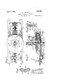
These and other objects I attain by the construction shown in the accompanying drawings, wherein for the purpose of illusmy invention and wherein 'tration is shown a preferred embodiment of Figure 1 is a plan view of a drilling aparatus constructed invention;
Figure 2 is a 'view partially in section and partially in elevation of the apparatus showing the positions assumed by the parts when the'device is employed for coupling sections of drill pipe; v
Figure 3 is an enlarged View showing the outer table in section and a portion of the ring broken away, the ring being in the position in which the outer and inner tables are locked to one another;
Figure 4 is a similar view showing the position of the ring when the parts are an: locked and illustrating the fact that the brake is applied at this time; and
Figure 5-is a detailed view of the operating mechanism for the brake and ring elevating arm.
Figure 6- is a detail horizontal sectional view showing the connection between the table 20 and intermediate bushing 16;
Figure 7 is a detail horizontal sectional view showing the spline engagement between the locking ring and driving table.
Referring now more particularly to the drawings, the numeral 10 indicates the usual skids employed as a support for a base 11 and its extension 12, hereinafter to be in accordance with my bushing 16 which has a depending guiding flange 17 entering the central bore of the base l1.
This bushing has a. central bore 18, the
,upper portion of which is conical, as indicated at 19, and provides a seat for a downwardly tapering inner table 20 which Is provided with a central slip receiving bore 21 having slips 22 arranged therein for engagement with a drill pipe 23 or with the drill stem (not herein disclosed). The upper portion of the intermediate bushing 16 and an overlying portion of the table 20 are formed with interlocking teeth 24 and 25, these teeth engaging when the central table is fully seated in the intermediate bushing to lock these two members to one another, as respects rotary motion. The upper surface of the central table is formed with sockets 26, the purpose of which will hereinafter appear.
The upper surface of the intermediate bushing provides a roller track 27 with whlch are engaged rollers 28 upon which is seated the inner lower face of an outer' table 29. This outer table 29 has its upper surface substantially flush with the upper surface of the inner table 20 and the inner table is preferably provided with a hook flange 3O engaging over an upstanding rib 31 formed upon the upper surface of the table 29 at the inner edge thereof. Formed in the under surface of the outer table 29 and partially overlying the upper surface of the intermediate bushing is an annular groove 32, the outer wall of which is provided with vertically extending notches forming teeth 33 which are slidably engaged by similar teeth 34 formed upon the outer surface of a locking ring 35. This locking ring has at its upper end an inturned flange 36 overlying the upper outer surface of the intermediate bushing 16 and opposing faces of this flange and the bushing are provided with teeth 37 and 38 which engage when the locking ring is lowered to a predetermined extent. When the teeth 37 and 38 are engaged, the intermediate bushing is locked to the outer table 29 so that the tables 20, 29, and the intermediate bushing 16 rotate as a unit. The upper surface of the table 29 has circumferentially spaced sockets 39, the pur pose of which will presently appear.
As regards its remaining structure, the outer table 29 resembles the tables now in use upon rotary well drilling apparatus having formed upon its under outer edge gear teeth 40 for engagement by a drive pinion 41 secured to a shaft 42 mounted in bearings 43 carried by the base extension 12. The under surface of the table is further formed with the usual depending portion 44 having at its lower end an outstanding outwardly directed horizontal flange 45 for engagement by hold-down blocks 46 carried by the base 11.
Extending about the outer surface of the intermediate bushing within a groove 47 formed therein is a friction brake band 48,-
one end of which is adjustably connected, as at 49, to a standard 50 arising from the base 11. To the opposite end of this band is connected a crank arm 51 of a rock shaft 52 mounted for rocking movement in the base 11 and having beneath the base a second arm 53. The skids 10 are connected by a cross brace 54 uponwhich in alignment with the free end of the arm 53, a cylinder 55 is secured.- Upon the rod 56 of the piston of this cylinder a cross head 57 is connected by a link 58 with the free end of the arm 53. This rod 56 preferably extends from the opposite end of the cylinder 55 and is there connected with the lower end of a suitably pivoted lever 59 by means of which the rod may be shifted without the use of fluid pressure. Ordinarily movement of the rod will be controlled by fluid pressure and a suitable valve of any usual construction and not herein disclosed for the reason that it forms no part of my invention.
being loosely directed through the yoke and having a spring 63, one end of which engages the yoke and the opposite end of which engages the adjacent end of the cross head 57.
In the operation of the device. it will be obvious that if the rod 56 be shifted in the direction of the arrow of Figure 5, the result will be that the rollers 61 of the levers 60 will be broughtinto engagement with the locking ring and this locking ring elevated and at the same time, this rod through the arm 53 will constrict the brake band 48 upon the intermediate bushing" 16, checking the rotation thereof. Since the elevation of the locking rings frees the intermediate hushing, the table 29 will now rotate alone. When the rod is moved in the opposite direction, the brake band will be loosened and at the same time, the locking ring will be lowered and will lock together the outer table 29 and the intermediate bushing so that both tables 20 and 29 are rotating. When it is desired to employ the.device for coupling pipe, the position and operation first described is employed, that isto say, the outer table is driven from'the shaft .42 while the inner table is held against rotation'by the friction band. Before rotation is started, posts 64 and 65 are entered in the sockets26 and. 39 respectively. Against the post 64 is engaged the handle of a wrench 66 which is employed forholding the lower pipe section 23 against rotation. Against the post 65. is engaged the handle of a second wrenchfi? which engages the upper pipe section 23, for the purpose of rotating the same to cause the coupling of these sections. The outer table is now thi'own into rotation and this rotation maybe continued until the coupling is entirely completed at which time the drag transmitted to the inner table and through the posts 64, 65 and wrenches66 and 67 will be in' turn transmitted to the intermediate bushing 16: thereof and this intermediate bushing caused to rotate against the artion' of its friction band so that no damage will result to'the threads of the coupling. It will, of course, be obvious that during drilling operations if, at any time, it is desired to temporarily disconnect the. drilling string from the drive, .this may be accomplished by operating the rod 56 and not only will a disconnection be efiected but the inner table will be braked against rotation.
Since the structure hereinbefore set forth is obviously but one preferred example of my invention, I do not wish to be understood.
as limltmg myself to. the specificstructure thereof except as hereinafter claimed.
I claim v 1. In a well drilling machine and in combination a base, a member rotatable upon the means associated therewithffor base having a drlll pipe and securing the supporting same against rotation'with relation to the member, a table concentric with the member, means-for rotating the table and means operable during rotation of the tablev for locking the tableand said-member against relative-rotation and operating means for said lockin 'means stationary with relation to said tab e.
2. In a well drilling machine and in coinbination a base, a member rotatable upon the base having means associated therewith for supporting a drill pipe andsecuring the same against rotation with relation to the member, atable concentric with the member, means for rotating the table, locking.
means operable during rotation of the table for locking the table and said member against relative rotation comprising a. ring member, a table concentric with the member, means for rotating the table and locking means operable during rotation of the table for locking the table and said member against relative rotation and means operable to brake rotation ofthe member until a predetermined pressure is, applied thereto to rotate the same.
4. In a well drilling machine and in combination a base, a member rotatable upon the base having means associated therewith for supporting a drill pipe and securing the same against rotation. with. relation to the member, a table concentric with the member, means for rotating the table, locking means operable during rotation ofthe table for locking the table and said member against relative rotation, means operable to brake rotation of the member until a predetermined pressure is applied thereto to rotate the same and means for simultaneously applying the braking means and releasing said locking means. r
' 5. In awell drilling machine and in combination a base, a member rotatable upon the base having means associated therewith \for supporting a drill pipe and securing the same against rotation with relation to the member, a table concentric with the member, "means for rotating the table, locking means operable during rotation of the table for locking the table and said member against relative rotation, means operable to brake rotation of tlie member until a predetermined pressure is applied thereto to rotate the same and wrench posts removably sup- I- ported from said table and said member.
6. In a well drilling machine and in combination a base, a member rotatable upon the base having means associated therewith the clutch teeth of the. locking ring engage in one position of the locking ring, means for shifting said ring to inoperative position comprising a plurality of levers having rollers engaging the ring at circumferentially spaced points and means for simulta- I neously shifting the levers, said ring having the teeth thereof normally engaged with the teeth of the member.
7. In a well drilling machine and in combination a base, a member rotatable upon the'base having means associated therewith for supporting a drill pipe and securing the same against rotation with relation to the member, a table concentric with the member, means for rotating the table, locking means operable during rotation of the the teeth thereof normally engaged with the teeth of the member, a brake band associated with said member and means for tightening the brake band upon the member as the levers are operated to shift said ring to inoperative position.
8. In a well drilling machine and in combination a base, a member rotatable upon the base having means associated therewith for supporting a drill pipe and securing the same against rotation with relation to,the member, a table concentric with the member, means for rotating th table, locking means operable during rotation of the table for locking the table'and said member against relative rotation comprising a ring splined to said table and having clutch teeth, clutch teeth upon said member with which the clutch teeth of the locking ring engage in one position of the locking ring, means for shifting said ring to inoperative 'POSIUOII, comprising a plurality of levers having rollers engaging the ring at cir'cum'ferentially spaced points, means for simultane-- V ously shifting the levers, said ring having the teeth thereof normally engaged with the teeth of the member, a brake band vassociatedwith said member, means for tightening the brake band upon the member as the levers are operated to shift. said ring to inoperative position comprising a cylinder, a
piston therein,a| rod for the piston, a;;cou- V nection between the rod and one end of the rod and the conn ction between said levers.
9. In a well drilling machine and in combination a base, a member rotatable upon the base having means associated therewith for supporting a drill pipe and securing'the same against rotation with relation to the,
member, a table concentric with the member, means for rotating the table, locking means operable during rotation of the table for locking the table and said member against relative rotation comprising a ring splined to said table and having clutch teeth, clutch teeth upon said member with which the clutch teeth of the locking ring engage in one position of the locking ring, means for shifting said ring to inoperative position comprising a plurality of levers having rollerS engaging'the ring at circumferentially spaced points, means for simultaneously shifting the levers, said ring having the teeth thereof normally engaged with the teeth of the member, a brake band associated with said member and means for tightening the brake band upon the member as the levers are operated to shift said ring to inoperative position eomprising a cylinder, a p ston therein, a rod for the piston, a con-' nection between the rod and one end of the brake band, a connection between the rod and the connection between said levers, and means for manually shifting said rod.
10. In a well drilling machine and in combination a base, a member rotatable upon the base having means associated therewith for supporting a drill pipe and securing the member;
11. In a well drilling machine and in combination a base, a member rotatable upon the base having means associated therewith for supporting a drill pipe and securing the same against rotation with relation to the member, a table concentric with the member, means for rotating the table, locking means operable during rotation of the table for locking the table and said member against relative rotation, a brake band surrounding said member and having one end thereof adjustably secured to said base and means for shifting the opposite end of the brake band to cause/ the band to engage or release said member and for simultaneously rendering the-locking means'inoperable.
'12, In a well drilling machine and in com- I bination a base, an lntermediate bushing brake band and a connection between therotatable upon the base and having a bore, c
inserted having teeth engaging the teeth formed upon said intermediate bushing whereby the intermediate bushing and" table arelocked against rotation with relation to one another, said table having a central bore aflording slip seats, means for braking the intermediate bushing, a rotatable element concentric with the intermediate bushing a table insertable in said bore and when formed upon said and means for locking the rotatable element 13. In a well drilling machine and in combination a base, an intermediate bushing rotatable upon the base and having a bore, a table insertable in said bore and when inserted having teeth engaging the teeth intermediate bushing whereby the intermediate bushing and table are locked against rotation with relation to,
one another, said table having a central bore affording slip seats, means for braking the intermediate bushing, a rotatable element concentric with the intermediate bushing, the rotatable element being rotatably mounted upon the intermediate bushing and having splined thereto a ring having teeth, the mtermediate bushing having teeth for coactlon with the teeth of the ring and means for shifting the ring to engage or disengage the teeth during rotation of the rotatable element.
14. In a well drilling machine and in combination a base, an intermediate bushing rotatable upon the base and havingl a bore, a table insertable in said bore andw en inserted having teeth engaging the teeth formed upon said intermediate bushing whereby the intermediate bushing and table are locked against rotation with relation to one another, said-table having a central bore afiording slip seats, means for braking the intermediate bushing, a rotatable element concentric with the intermediate bushing, the rotatable element being rotatably mounted upon the intermediate bushing and having splined thereto a ring having teeth, the intermediate bushing having teeth for coaction with the teeth of the ring, means for shifting the ringto engage or disengage the teeth during rotation of the rotatable element comprising a plurality of levers having rollers engaging the ring at circumferentially spaced points and means for simultaneously shifting the levers. I I
15. In a well drilling machine and in com-' bination a base, an intermediate bushing rotatable upon the base and having a, bore, a
table insertable in said bore and when inserted having teeth engaging the teeth formed upon said intermediate bushing whereby the intermediate bushing and table are locked against rotation with relation to one another, said table having a central bore afli'ording slip seats, means for braking the intermediate bushing, a rotatable element concentric with the intermediate bushing, the rotatable element being rotatably mounted upon the intermediate bushing and having splined thereto a ring having teeth, the intermediate bushing having teeth for coaction" with theteeth of the ring, means for Shiite mg the ring to engage or disengage the teeth during rotation of the rotatable element supporting a a plurality of levers having rollthe ring at circumferentiallyr spaced points, meanslfor simultaneously shifting the levers, a brake for the intermediate bushing and a connection between the last named means and the brake whereby the brake is applied as the ring is shifted to disengage said teeth.
16. In a well drilling machine and in combination, a base, a member rotatable upon the base having associated therewith means supporting a drill pipe and securing the same against rotation with relation to the member, a table concentric with and rotatably supported by the member, means for rotating the table and locking means shift able axially ofsaid table and member for locking the table and member against relative rotation and means for shifting said locking means during rotation of the "table.
17. In a well drillin machine and in combinationa base, a mem er rotatable upon the base havin associated therewith means supporting a rill pipe and securing the same against rotation with relation to the member, a tableconcentric with and rotatably' supported by the'member, means for rotating the table, locking means shiftable axially of said table and member for looking the table and member against relative rotation, means for shifting said locking means during rotation of the table, the under surface of the table having an annular groove one wall of which is provided with vertically extending teeth, said locking means comprising a ring having teeth engaging the teeth of ing said member, the member having teeth for engagement by the last named teeth of the ring when in one position.
18. In a well drilling machine and in combination a base, a member rotatable upon the base having associated therewith means drill pipe and securing the same against rotation with relation to the member, a table concentric with and rotat-. ably supported by the member, means for rotating the table, locking means shiftable axially of said table and member for locking thetable and member against relative 'rotation, during rotation of the table, the under surcomprising ers engaging ,face of the table" having an annular groove one wall of which is provided-With vertically extending teeth, said locking means comprising a ring having teeth engaging the teeth of the table, other teeth confronting said the table and other teeth confrontmeans for shifting saidlocking means member, the member having teeth for en gagementby the last named ring when in one position, said shifting means comprising levers pivoted upon sai base and having rollers engaging the ring and means levers.
19,;In a well drilling machine and in com- F teeth of the for: simultaneously shifting the v bination a base, a member rotatable upon the base having means associated therewith for supporting a drill pipe and securing the same against rotation with relation to the member, a table concentric with the member, means for rotating the table and means operable to brake rotation of the member until a predetermined pressure is applied thereto to rotate the same.
20. In a well drillin machine and in combination a base, a mem er rotatable upon the base having means associated therewith for supporting a drill pipe and securing the same against rotation with relation to the member, a drive including a table concentric with the member, means for clutching and unclutching the drive to the member, a brake for the member and means for simultaneously clutch 21. In a well drilling machine and in combination a base, a member rotatable upon the base having means associated therewith for supportinga drill pipe and securing the same against rotation with relation to the member, a drive including a table concentric with the member, means for clutching and unclutching the drive to the member, a brake for themember'and means for simultaneouslyapplying the brake and connecting the clutch operable during operation of the drive and stationary with relation to the table.
In testimony whereof I afiix my signature.
LEE J. BLACK.
applying the brake and connecting the
Priority Applications (1)
| Application Number | Priority Date | Filing Date | Title |
|---|---|---|---|
| US31908A US1580002A (en) | 1925-05-21 | 1925-05-21 | Rotary well-drilling apparatus |
Applications Claiming Priority (1)
| Application Number | Priority Date | Filing Date | Title |
|---|---|---|---|
| US31908A US1580002A (en) | 1925-05-21 | 1925-05-21 | Rotary well-drilling apparatus |
Publications (1)
| Publication Number | Publication Date |
|---|---|
| US1580002A true US1580002A (en) | 1926-04-06 |
Family
ID=21862063
Family Applications (1)
| Application Number | Title | Priority Date | Filing Date |
|---|---|---|---|
| US31908A Expired - Lifetime US1580002A (en) | 1925-05-21 | 1925-05-21 | Rotary well-drilling apparatus |
Country Status (1)
| Country | Link |
|---|---|
| US (1) | US1580002A (en) |
Cited By (2)
| Publication number | Priority date | Publication date | Assignee | Title |
|---|---|---|---|---|
| US2450103A (en) * | 1945-09-13 | 1948-09-28 | Austin Frank | Sucker rod backoff wheel |
| US3915243A (en) * | 1973-07-16 | 1975-10-28 | Gardner Denver Co | Rotary drive and joint breakout mechanism |
-
1925
- 1925-05-21 US US31908A patent/US1580002A/en not_active Expired - Lifetime
Cited By (2)
| Publication number | Priority date | Publication date | Assignee | Title |
|---|---|---|---|---|
| US2450103A (en) * | 1945-09-13 | 1948-09-28 | Austin Frank | Sucker rod backoff wheel |
| US3915243A (en) * | 1973-07-16 | 1975-10-28 | Gardner Denver Co | Rotary drive and joint breakout mechanism |
Similar Documents
| Publication | Publication Date | Title |
|---|---|---|
| US1708316A (en) | Blow-out preventer | |
| US2577068A (en) | Well packer | |
| US1560763A (en) | Packing head and blow-out preventer for rotary-type well-drilling apparatus | |
| US2491711A (en) | Hydraulic slip | |
| US1341702A (en) | Rotary drilling-machine | |
| US1580002A (en) | Rotary well-drilling apparatus | |
| US2361094A (en) | Setting tool for use in wells | |
| US2379394A (en) | Packer holding device | |
| US2352423A (en) | Packer assembly | |
| US2712854A (en) | Adjustable casing connector | |
| US3191682A (en) | Hydraulically-actuated well packers | |
| US2633917A (en) | Removable subsurface well tool | |
| US2387682A (en) | Rotary jar and safety joint | |
| US2365327A (en) | Adjustable anchor for packers | |
| US2400970A (en) | Lock device for well tools | |
| US1686945A (en) | Weight-regulating device | |
| US2618342A (en) | Control device for well tools | |
| US2122742A (en) | Packer for use in wells | |
| US2360088A (en) | Drilling tool | |
| US2390112A (en) | Well packer | |
| US3051240A (en) | Multiple testing and pressuring apparatus | |
| US1811939A (en) | Drilling apparatus | |
| US2671513A (en) | Lock device for well tools | |
| US2906347A (en) | Subsurface well tools | |
| US2215632A (en) | Pipe cutting tool |