US1576216A - Cycle, motor cycle, and the like - Google Patents
Cycle, motor cycle, and the like Download PDFInfo
- Publication number
- US1576216A US1576216A US602160A US60216022A US1576216A US 1576216 A US1576216 A US 1576216A US 602160 A US602160 A US 602160A US 60216022 A US60216022 A US 60216022A US 1576216 A US1576216 A US 1576216A
- Authority
- US
- United States
- Prior art keywords
- frame
- cycle
- spring
- engine
- motor
- Prior art date
- Legal status (The legal status is an assumption and is not a legal conclusion. Google has not performed a legal analysis and makes no representation as to the accuracy of the status listed.)
- Expired - Lifetime
Links
Images
Classifications
-
- B—PERFORMING OPERATIONS; TRANSPORTING
- B62—LAND VEHICLES FOR TRAVELLING OTHERWISE THAN ON RAILS
- B62K—CYCLES; CYCLE FRAMES; CYCLE STEERING DEVICES; RIDER-OPERATED TERMINAL CONTROLS SPECIALLY ADAPTED FOR CYCLES; CYCLE AXLE SUSPENSIONS; CYCLE SIDE-CARS, FORECARS, OR THE LIKE
- B62K3/00—Bicycles
- B62K3/02—Frames
Definitions
- This invention comprises certain improvements in or relating to cycles, motor cycles and the like; and it has for its object an in'iproved construction of frame work whereby road shocks or vibration will be more eiiiciently absorbed than is the case with machines at present constructed.
- A*according to the present improvements not only is the rider protected from shocks and vibration, but the entire mechanism of a motor cycle is also protected from shock and vibration.
- the rear wheel and engine are mounted on a frame pivoted tothe main frame of thel machine, such pivoted frame being under spring control.
- the front fork is also sprung in an improved manner and is under the control of the spring controlling the rear wheel and parts movable therewith.
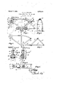
- Figure 1 is a side elevation of a machine constructed according to this invention.
- Y Figure 2 is a side elevation of the ⁇ main fran'ie.
- Figure 3 is a front elevation of the front fork and handle bar detached from the main frame.
- Figure 4 is a side elevation of the parts shewn by Figure 3.
- Figure 5 is a plan ofthe frame carrying the rear wheel and engine.
- Figure ti is a section ofthe main frame on line of Figure 1.
- Figure 7 is a side elevation of the frame carrying the rear wheel and engine and at tendant parts.
- the machine comprises a main frame 1 which may be formed of two metal pressings which are jointed together longitudinally of the frame.
- the members of the frame may be channelled as seen in cross section.
- This construction of frame is given by way of example only and may be of any other desired construction 0r shape.
- a frame 2 is mounted to pivot about the axis 3 on this frame 1, such frame 2 supporting the rear wheel 4.
- the upper end ot' this frame 2 Ais i spring' supported from the frame 1 icy-means ofthelead spring 5.
- the frame 2 carries the engine 6 and the attendant parts such as the gear box and magneto.
- the cylinder heads of the engine are held by set pins 7 which pass through transverse bars 2b .of the frame rlhe frame 2 is fixed to the shaft 8 the axis of which coincides with the axis 3 carried by the crank case of the engine, and such shaft is pivotally mounted, as shewn, in the steel plates 9 of thc frame 1.
- the rear wheel is spring' ,mounted and the frame carrying thc engine and attendant parts is also spring mounted thus reducing wear and tear of the engine.
- the rear ⁇ wheel will vibrate concentric with the driving sprocket, pulley or driving member 5G of the engine, thereby not interfering with the drive during such vibration.
- the spring 5 is riveted to the underside of the top member' of the frame 1 and is preferably carried forward t0 control the spring forli 12.
- the fork comprises a member lcarrying the front wheel, which member is slidably mounted in the head of the frame 1 through the medium of the rotatably mounted collar 14, which collar carries the trunnions 15 upon which, are mounted the blocks 16 adapted to travel in the slots 17 in the head of the frame 1.
- the collar 14 is mounted on ball bearings at its upper and lower ends.
- the handle bar 18 is rotatably mounted on the head of thc frame 1 in suitable ball bearings and such handle bar carries a member 19 having a slot 2O therein for receiving the projection 21 carried by the member 13.
- the collar 14 carries a projection 22 which is connected to -the spring 5 by means of the link 23. The front fork can therefore travel upwardly and pivoton the trunnions 15 under the control of the spring 5.
- the petrol and oil tank is conveniently fitted to the frame 1 in the position as shewn. lVith the machine thus constructed the parts are spring balanced substantially around the centre of load of the machine.
- the saddle 24 is spring carried from the frame 1 conveniently by means of the leaf spring 25 fixed to the upper member of the .frame 1 and by two leaf springs 26 secured on brackets 27 on the frame-l@ Claws' 1.
- A. motor cycle comprising a main frame,
- a leaf ASpring Vcarried thereby7 a frame carrying the rear Wheel and engine pivotally mounted on the main frame under the 5 Control of the said leaf spring and a fork mounted on the main frame under 'the control of the Said leaf spring.
Description
March 9 1926.
F. J. H. PHILLIPS CYCLE, MOTOR CYCLE, AND THE LIKE Filed NOV. 20, 1922 Patented Mar. 9, 1926,
Unir-ee s 'rares PATENT oF-Fior.
FREDERICK JOHN HENRY PHILLIPS, '0F LLANEL'LY,
Applcation filed November 20, 1922. SerialNo. 602,160.
To all whom t may concern.'
`Bc it known that 1, Fnnminicn Joli-IN HENRY lirrmgrrs, a subject of the l'cling of Great Britain, residing at 18 Bryi'icacraw ylerrace. Llanelly, ldlales, have invented certain new and useful Improvements in Cycles, Motor Cycles, and the like, of which the following is a specification.
This invention comprises certain improvements in or relating to cycles, motor cycles and the like; and it has for its object an in'iproved construction of frame work whereby road shocks or vibration will be more eiiiciently absorbed than is the case with machines at present constructed.
A*according to the present improvements not only is the rider protected from shocks and vibration, but the entire mechanism of a motor cycle is also protected from shock and vibration. In the case of a motor cycle the rear wheel and engine are mounted on a frame pivoted tothe main frame of thel machine, such pivoted frame being under spring control. The front fork is also sprung in an improved manner and is under the control of the spring controlling the rear wheel and parts movable therewith.
Figure 1 is a side elevation of a machine constructed according to this invention.
Y Figure 2 is a side elevation of the `main fran'ie.
Figure 3 is a front elevation of the front fork and handle bar detached from the main frame.
Figure 4 is a side elevation of the parts shewn by Figure 3.
Figure 5 is a plan ofthe frame carrying the rear wheel and engine.
Figure ti is a section ofthe main frame on line of Figure 1.
Figure 7 is a side elevation of the frame carrying the rear wheel and engine and at tendant parts.
According to a convenient embodiment of this invention, as applied to a motor cycle, the machine comprises a main frame 1 which may be formed of two metal pressings which are jointed together longitudinally of the frame. The members of the frame may be channelled as seen in cross section. This construction of frame is given by way of example only and may be of any other desired construction 0r shape. A frame 2 is mounted to pivot about the axis 3 on this frame 1, such frame 2 supporting the rear wheel 4. The upper end ot' this frame 2 Ais i spring' supported from the frame 1 icy-means ofthelead spring 5. The frame 2 carries the engine 6 and the attendant parts such as the gear box and magneto. The cylinder heads of the engine are held by set pins 7 which pass through transverse bars 2b .of the frame rlhe frame 2 is fixed to the shaft 8 the axis of which coincides with the axis 3 carried by the crank case of the engine, and such shaft is pivotally mounted, as shewn, in the steel plates 9 of thc frame 1. it will thus be seen that the rear wheel is spring' ,mounted and the frame carrying thc engine and attendant parts is also spring mounted thus reducing wear and tear of the engine. It will also be seen that the rear `wheel will vibrate concentric with the driving sprocket, pulley or driving member 5G of the engine, thereby not interfering with the drive during such vibration. The rod shewn, in the steel plates 9 of the frame 1.
The spring 5 is riveted to the underside of the top member' of the frame 1 and is preferably carried forward t0 control the spring forli 12. According to- .one con-` venient construction the fork comprises a member lcarrying the front wheel, which member is slidably mounted in the head of the frame 1 through the medium of the rotatably mounted collar 14, which collar carries the trunnions 15 upon which, are mounted the blocks 16 adapted to travel in the slots 17 in the head of the frame 1. The collar 14 is mounted on ball bearings at its upper and lower ends. The handle bar 18 is rotatably mounted on the head of thc frame 1 in suitable ball bearings and such handle bar carries a member 19 having a slot 2O therein for receiving the projection 21 carried by the member 13. The collar 14 carries a projection 22 which is connected to -the spring 5 by means of the link 23. The front fork can therefore travel upwardly and pivoton the trunnions 15 under the control of the spring 5.
The petrol and oil tank is conveniently fitted to the frame 1 in the position as shewn. lVith the machine thus constructed the parts are spring balanced substantially around the centre of load of the machine.
The saddle 24 is spring carried from the frame 1 conveniently by means of the leaf spring 25 fixed to the upper member of the .frame 1 and by two leaf springs 26 secured on brackets 27 on the frame-l@ Claws' 1. A. motor cycle comprising a main frame,
a leaf ASpring Vcarried thereby7 a frame carrying the rear Wheel and engine pivotally mounted on the main frame under the 5 Control of the said leaf spring and a fork mounted on the main frame under 'the control of the Said leaf spring.
2. A motor cyclecolnprsing a nlan frame, a leaf spring carried thereby, a frame 10 carrying the rear Wheel "and .engine pvotally mounted on the main frame under the control Iof the said leaf spring, a fork slidably mounted in the head of the main frame under control of said leaf spring, a handle bal" rotatably mounted on the head of the main frame controlling theturnng of the fork.
In Wtnesswhel'eof I have signed this Speecation.
FREDERICK JOHN HENRY PHILLIPS.
Priority Applications (1)
| Application Number | Priority Date | Filing Date | Title |
|---|---|---|---|
| US602160A US1576216A (en) | 1922-11-20 | 1922-11-20 | Cycle, motor cycle, and the like |
Applications Claiming Priority (1)
| Application Number | Priority Date | Filing Date | Title |
|---|---|---|---|
| US602160A US1576216A (en) | 1922-11-20 | 1922-11-20 | Cycle, motor cycle, and the like |
Publications (1)
| Publication Number | Publication Date |
|---|---|
| US1576216A true US1576216A (en) | 1926-03-09 |
Family
ID=24410221
Family Applications (1)
| Application Number | Title | Priority Date | Filing Date |
|---|---|---|---|
| US602160A Expired - Lifetime US1576216A (en) | 1922-11-20 | 1922-11-20 | Cycle, motor cycle, and the like |
Country Status (1)
| Country | Link |
|---|---|
| US (1) | US1576216A (en) |
Cited By (4)
| Publication number | Priority date | Publication date | Assignee | Title |
|---|---|---|---|---|
| US2592981A (en) * | 1947-05-16 | 1952-04-15 | Sotecom S A | Two-wheel vehicle |
| US2792236A (en) * | 1954-05-05 | 1957-05-14 | Lionel B Jacquart | Front wheel suspension for two-wheeled vehicle |
| US4022484A (en) * | 1976-03-15 | 1977-05-10 | Davis William F | Motorcycle frame and suspension and methods of making and using the same |
| US20060060407A1 (en) * | 2004-09-21 | 2006-03-23 | Siddle Mark L | Methods and apparatus for conversion of motorcycle rear suspension |
-
1922
- 1922-11-20 US US602160A patent/US1576216A/en not_active Expired - Lifetime
Cited By (6)
| Publication number | Priority date | Publication date | Assignee | Title |
|---|---|---|---|---|
| US2592981A (en) * | 1947-05-16 | 1952-04-15 | Sotecom S A | Two-wheel vehicle |
| US2792236A (en) * | 1954-05-05 | 1957-05-14 | Lionel B Jacquart | Front wheel suspension for two-wheeled vehicle |
| US4022484A (en) * | 1976-03-15 | 1977-05-10 | Davis William F | Motorcycle frame and suspension and methods of making and using the same |
| US4087109A (en) * | 1976-03-15 | 1978-05-02 | Davis William F | Motorcycle frame and suspension and methods of making and using the same |
| US20060060407A1 (en) * | 2004-09-21 | 2006-03-23 | Siddle Mark L | Methods and apparatus for conversion of motorcycle rear suspension |
| US7137468B2 (en) * | 2004-09-21 | 2006-11-21 | Siddle Mark L | Methods and apparatus for conversion of motorcycle rear suspension |
Similar Documents
| Publication | Publication Date | Title |
|---|---|---|
| US1576216A (en) | Cycle, motor cycle, and the like | |
| US2908510A (en) | Frame structure for golf bag motor scooter | |
| US1197526A (en) | Balanced motor-wheel. | |
| US1148707A (en) | Frame of bicycles. | |
| US894060A (en) | Motor-vehicle. | |
| US1503935A (en) | Bicycle and motor drive therefor | |
| US2486095A (en) | Power drive attachment for bicycles | |
| US1418154A (en) | Front truck for street-sweeping machines | |
| US2525877A (en) | Bicycle | |
| US1470301A (en) | Shock absorber | |
| US1971541A (en) | Means for controlling the supporting strength of resilient vehicle supporting means | |
| US700A (en) | Photo-litho | |
| DE164930C (en) | ||
| US1316455A (en) | Planoqrapii co | |
| US1039943A (en) | Motor-cycle. | |
| US2034158A (en) | Delivery bike | |
| US1154821A (en) | Spring-frame for motor-cycles and like machines. | |
| DE412303C (en) | Gun arrangement on two-wheeled motorized vehicles | |
| US1210247A (en) | Motor-vehicle fender. | |
| DE329810C (en) | Brake for motor vehicles with a car axle swinging around the wheel axle | |
| DE805120C (en) | Bicycle with an elastic frame | |
| US1347100A (en) | Rear-springing device for motorcycles or tricars | |
| US971848A (en) | Seat for motor-cycles and other self-propelled vehicles. | |
| US827244A (en) | Vehicle. | |
| US1349415A (en) | Shock-absorbing steering mechanism |